Visual Navigation Method for Indoor Mobile Robot Based on Extended BoW Model
Xianghui Li, Xinde Li, Mohammad Omar Khyam, Chaomin Luo, and Yingzi Tan
1 Introduction
In the research field of mobile robots, navigation is very important and necessary, with its aim to make a robot move to the desired destination and while completing specified tasks as expected.
The first step in navigation is to build a model of the environment which can be a grid, geometric, topological or 3D one. However, Thrun proposed a hybrid method that combines grid and topological models[1,2], using the grid to represent local features and a Voronoi graph[3]topological structures. Wu Xujian et al. also proposed a visual navigation method for mobile robots based on a hand-drawn map[4]which provides the start and end information and approximate distance between these points, the approximate positions of landmarks the robot might meet during navigation, etc. Relative to traditional map-building models, such as grid, geometric and topological ones, we use the convenient hand-drawn map[5]. Although some researchers used artificial[6-10]and quasi-artificial landmarks (with some taken photos of natural ones in advance[4,5]), recognizing natural ones is essential for navigating successfully in real environments. However, unlike an artificial landmark, a natural one is not labeled.
Also, we should not restrict natural landmarks to specific objects due to the changeable environment; in other words, even if they change to some extent or adopt another form, a robot should still be capable of recognizing them using a visual sensor. In order to achieve our goal, we solve the problem of general object recognition in a real environment.
The BoW (Bag of Words) model is effective arithmetical means of general object recognition because of its simple strategy and robustness for determining an object’s position and deformation in an image. However, as each feature is independent of the others in it, there is no spatial relationship to consider whereas such relationships among features could be useful for describing the internal structures of objects or highlighting the importance of their contextual visual information. Although research on this theme is becoming more and more popular[11-19], there is still room for improvement.
In this paper, we propose a novel extended BoW method which works in the following statistical way. A multi-dimensional vector is used to describe an image with all its elements divided into two parts: one describes its local features; and the other is the spatial relationships among them. Then, we use the SVM (Support Vector Machine) classifier to train our model to obtain discriminant functions and, taking real time into account, GPU (Graphic Processing Unit) acceleration arithmetic to speed up image processing. Finally, this method is successfully applied to indoor mobile robot navigation.
2 Building Model of Environment
Building a model of the environment aimed at planning a path for a mobile robot involves feature extraction and information representation.
It is not necessary for many biological systems, such as those of human beings, butterflies and bees, to obtain precise distance information when perceiving their environments through their visual systems as they navigate by remembering some key landmarks based on qualitative analysis.
Based on the method proposed in [5], we design a hand-drawn map for guiding a robot’s navigation with the advantage that we do not need to input detailed environmental information into the robot and enables our navigation model to handle dynamic situations, such as when some landmarks change often or a person walks without stopping around the robot. We require only the starting point and orientation of the robot, the route and its approximate physical distance, and rough estimates of the locations of landmarks the robot might encounter during navigation.
Our novel extended BoW model for general object recognition proposed to overcome the challenge of recognizing natural landmarks is discussed in the next section.
3 Recognition of Landmarks
Recognizing different objects which belong in the same category and filtering complex backgrounds are the most difficult problems that might be faced in the course of general object recognition in a real environment. Every determinate object has its own characteristics, such as local parts and spatial relationships with others. While a human being can understand the advanced semantic features of a picture, a computer can comprehend only the raw information in an image. However, it is still very helpful to refer to the human vision system because the course of general object recognition is analogous to a human’s judgment, that is, firstly, descriptors of general objects are established, then their categories determined through machine learning and, finally, the learned model used to classify and recognize new objects[20].
3.1 Overview of recognition algorithm
The method proposed in this paper, the framework of which is presented in Fig.1, follows the principle of general object recognition, that is, firstly, it describes an image, then learns the object model and, finally, classifies objects.
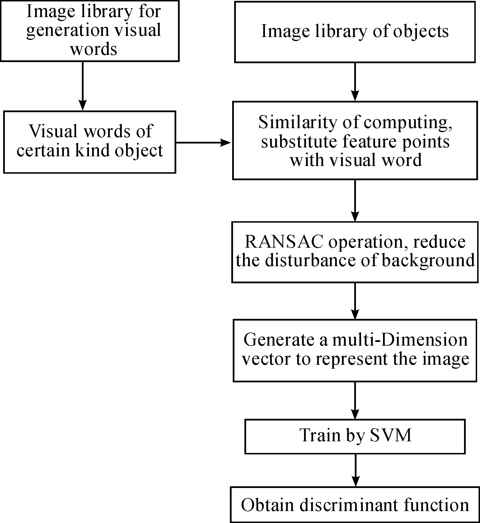
Fig.1 Framework of extended BoW model.
3.2 Building vision code library
In 1999, Professor G. David[21]proposed the SIFT (Scale-invariant Feature Transform) algorithm based on the scale space, which is invariant in terms of translation, rotation and zoom, and then improved it in 2004[22]. It is widely used for object recognition, and has a very strong image-matching capability with the following general characteristics.
a) A SIFT feature is a local feature of an image which remains invariant of translation, rotation, zoom, illumination, occlusion and noise and even maintains some degree of stability with a change in vision and affine transformation.
b) It has an abundance of information which is very helpful for fast and accurate image matching.
c) It is fast which may satisfy the real-time requirements of image matching after optimization.
d) It has strong extendibility which may be associated with other feature vectors.
Therefore, in this paper, we choose the SIFT algorithm to detect key points; for example, if we want to construct a code library of cars, first we choose pictures of different cars from different views and then detect key points using this algorithm.
After completing feature detection, we need to establish a vision code library using the large number of ‘words’ we obtain from detecting many images. However, as some SIFT descriptors are similar to those of other algorithms, it is necessary to cluster these vision words. K-means is a common clustering method[23]which aims to group elements in K centers according to the distance between an element and a center, and obtain the clustering centers based on continuous iterations; for example, if the elements for clustering are (x1,x2,x3,…,xn-1,xn) and every element is ad-dimensional vector, they are expected to cluster into K sets according to the sum of their minimum average variances (s={s1,s2,s3,…,sk-1,sk}) as:
(1)
whereμiis the average ofsi[25].
Based on experience, we adoptk= 600 and complete the construction of a vision code library in which every code is a 128-dimension SIFT description vector after K-means clustering.
3.3 Pre-processing images
As a computer can understand only raw information, acquiring an advanced meaning that reflects an object’s appearance is the major difficulty of general object recognition.
As previously mentioned, we obtain a vision code library of certain objects and, before describing an image, compute the similarity between a local feature and every word in the library. If a similarity meets the threshold, this local feature is considered a key point that belongs to this image; for example, if there are N vision codes in a library and M local features in an image, the pseudo-code is as follows.
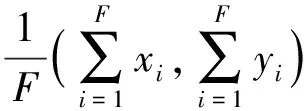
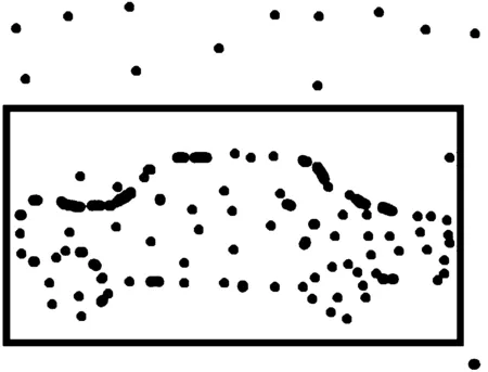
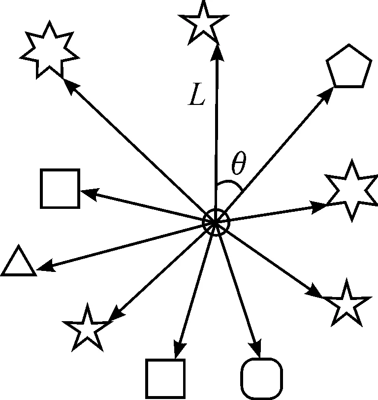
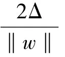
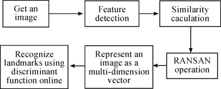
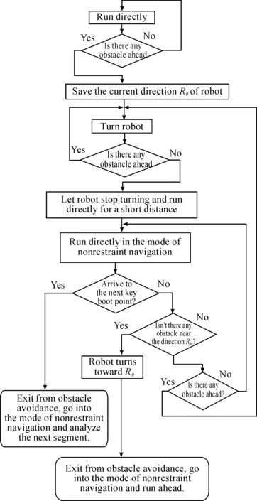
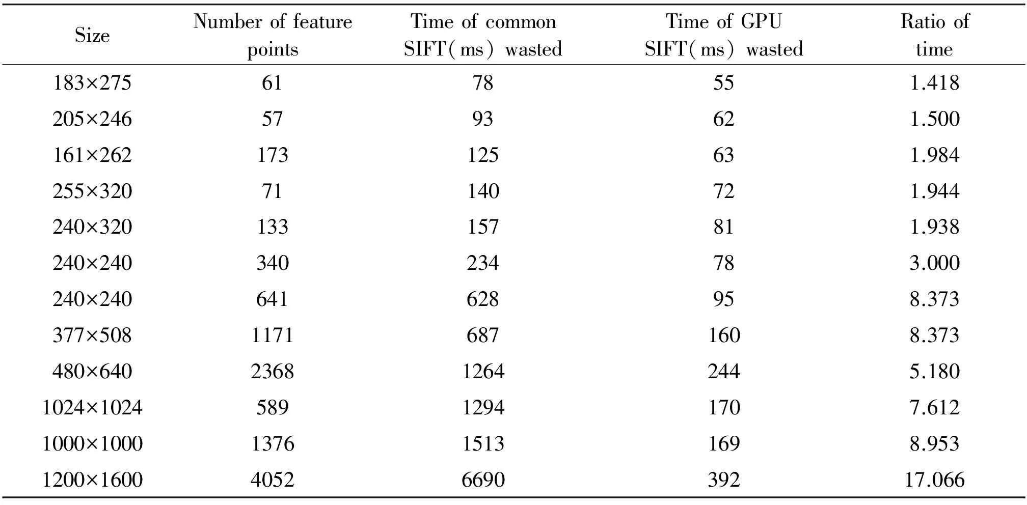
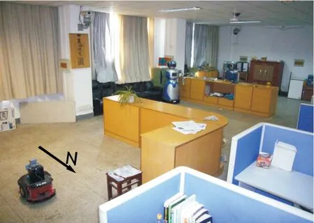
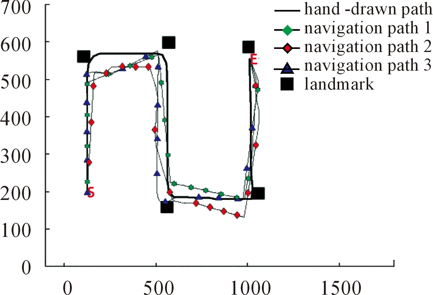
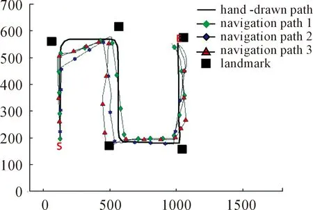
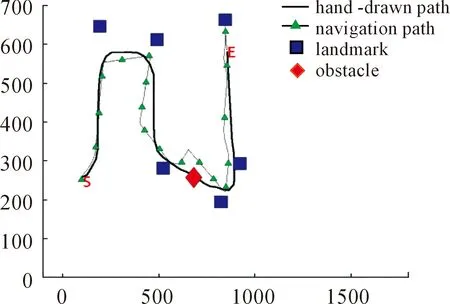
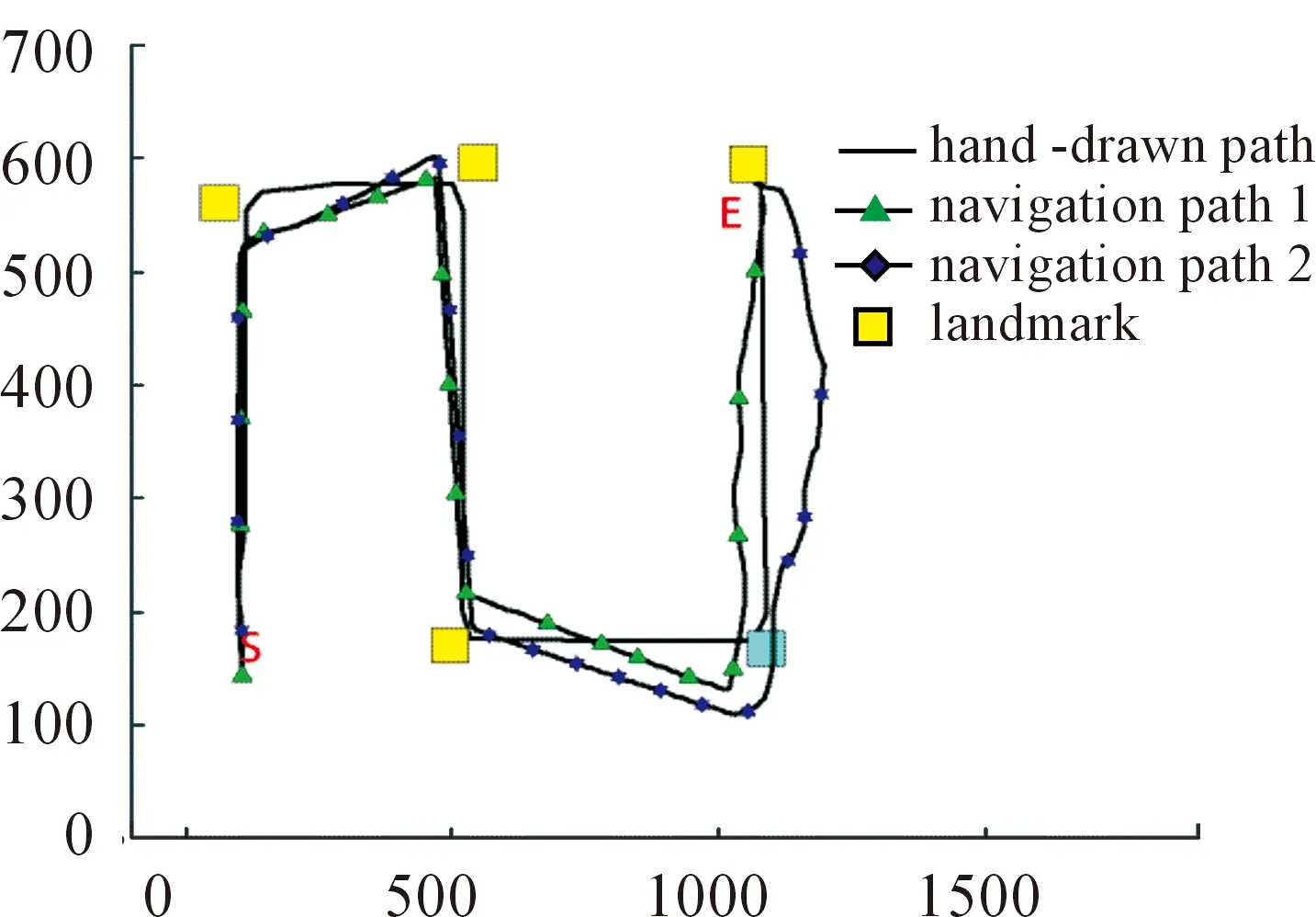
Whilei Whilej Ifsimilarity(Pi,Qj) Return true; Else return false. wherePidenotes the SIFT descriptor of theithlocal feature in an image andQjthat of thejthvision code in the library. We define (2) After performing local feature extraction, we take the normalized operation for every SIFT descriptor and believe that, although the remaining local features belong to the image, some are produced from the background. Therefore, an extra operation is required to delete them if: (1) the number of local features obtained from an image is much greater than that from the background after computing similarities; or (2) we want to further reduce the background disturbance based on the density distribution of the local features. Fig.2 shows the results if we obtainTlocal features fromMones after computing similarities. Obviously, if we want to obtain the object in the rectangle despite some disturbance, we may use RANSAC to reduce the negative influence on later image descriptions. For convenience, we use a circle to cover the area where the density of features is very high using the following pseudo-code. Whileiteration The points inside the model equal to the key points that were randomly selected fromTdatum, with the possible center of a circle: (3) The radius (R) can be defined as the maximum of the distances between the key points in the model and the possible center of a circle. For every key point that doesn’t belong to the model, if the distance is less than 1.2R, consider that it does belong and add 1 to the number of key points in the model. If the number of key points in the model is larger thanE(E=80%*T), consider this model to be correct and save the possible center of a circle and key points. Forj (4) If the distance (r,r∈[1,T]) is the minimum of all distances, save the model’s possible radius (r) and 80 % of its key points closest to the possible center and consider that they belong to the image. Fig.2 Feature points filtered from background. In our BoW model, a multi-dimensional vector was used to describe an image with all its elements grouped in two parts, one of which describes its local features and the other describes the spatial relationships among them. a) The local features are described based on the numbers of times words appear in the vision code; for example, if there are (x0,x1,x2,…,xP-2,xP-1) vision words in the library, the dimension of the vector isP, with the number of each dimension denoting the number of times the corresponding vision code appears. b) To describe the spatial relationships among the local features, we use the distance between a key point and the center of a circle, and the relative angle. The new center of the key points is expressed in equation (5), wheremindicates the number of key points after processing, and the geometric center is the center of a circle. As shown in Fig.3, the marks around it denote key points, for example, for the five stars in the upper right corner, the corresponding distance and angle areLandθ, respectively. (5) The Euclidean distances between every key point and the geometric center (xc,yc) were calculated as the distance, i.e., from (L1,L2,L3,…Lm-1,Lm). We take the middle distance as the unit length (L) and divide all the remaining ones into 0-0.5L,0.5L-L,L-1.5L,1.5L-MAXaccording to the ratioLi/L. A random key point were chosen and the angles were calculated between its half line and those of all the other key points to the center of the circle, i.e.,θin Fig.3. We obtain these angles after simple mathematical transformations (θ1,θ2,θ3…θm-1,θm), with that of one key point measured counter-clockwise. In fact, each angle is not very large and we divide them into five ranges of 0°-30°, 30°-60°, 60°-90°, 90°-120° and 120°-MAX. Fig.3 Spatial relationships of feature points. Therefore, 4×5=20 spatial relationships were generated and can be described every image using the vector as (x0,x1,x2,…,xP-3,xP-2,xP-1,y0,y1,y2…yQ-3,yQ-2,yQ-1). The dimension vectors (PandQ) stand for the numbers of times each vision word and a certain spatial relationship appear in an image, respectively. Since the distances and angles are relative, the descriptions of spatial relationships are invariant of translation, rotation and zoom, and finally they were normalized. During navigation, the camera continually acquires images and arrives at judgments according to the discriminant function which is trained offline and obtained as follows. Generally speaking, there are two kinds of classifiers that depend on the degree to which a human participates during learning, i.e., supervised and unsupervised. As the SVM has attracted a great deal of attention and recently achieved some good results, we use it to train our models as supervised classifiers. Its aim is to classify two kinds of patterns as far as possible according to the principle of the minimum structural risk by constructing a discriminant function. The training set is supposed to be{xi,yi},i=1, …,l,xi∈Rn,yi∈{-1,1}, which can be separated by a hyperplane ((w·x)+b=0), with a linear hyperplane at a distance (Δ) from the samples: (w·x)+b=0(w·x)+b=0, ||w||=1 if (w·x)+b≥Δ,y=1 if (w·x)+b≤-Δ,y=-1 The discriminant functions obtained offline, including those of many different kinds of objects, are used to build a database which a robot uses to recognize landmarks. During the running of a robot, its camera continually acquires image information and then every image is processed using the SIFT algorithm to obtain feature points. After computing similarities, the feature points that meet the specified threshold are saved and calculated according to RANSAC arithmetic to reduce background disturbance. Every image is represented as aP+Qdimension vector recognized by the offline discriminant functions in the database. Then, a series of recognition results is obtained to localize the robot itself, the framework of which is shown in Fig.4. Fig.4 Framework of online landmark recognition. We can summarize our recognition algorithm in two parts, i.e., offline and online. (1) Recognition of landmarks offline: in the phase of training and learning,I={I1,I2,I3,…,Im-2,Im-1,Im}, whereIis a set of images for generating visual words,A={A1,A2,A3,…,Aw-2,Aw-1,Aw}, whereAis a set ofwtraining images containing target objects with every image marked as +1 when trained; andB={B1,B2,B3,…,Bt-2,Bt-1,Bt},B, whereBis a set of training images not containing target objects with every image marked as -1 when trained. This phase involves the following three steps: a) a visual code library of imageIwas generated; b) every image inAandBwas represented as a multi-dimensional vector with background disturbance reduced; c) the SVM was used to train images and finally obtain the discriminant functions. (2) Recognition of landmarks online: a) an image was obtained, and its background disturbance was reduced and represented as a multi-dimensional vector; b) landmarks were recognized by using discriminant functions. The navigation flowchart shown in Fig.5 is clearly explained in [5]. However, our proposed general object recognition method for recognizing natural landmarks for robot navigation is different and requires photos of landmarks to be taken manually in advance and regarded as image-matching templates. Fig.5 Navigation flowchart. SIFT algorithm was used mainly to detect and acquire key points in the course of general object recognition by a 128-dimension vector. These points are some local extreme ones containing orientation information which are detected in different scale spaces of an image and can be described from the three views of scale, size and orientation. As this process takes a long time, it is necessary to use GPU acceleration to speed up the SIFT algorithm which occupies most of our algorithm’s time. The GPU is a concept with a great advantage over a Central Processing Unit (CPU) for image processing and the NVDIA released an official development platform, i.e., CUDA, on which we can compute SIFT code in a parallel manner. We test images of different sizes with different numbers of key points using: operating system -32 bit win7; flash memory -2G; CPU-Intel(R) Core(TM) 2Duo E7500@2.93GHz; GPU-nVIDIA GeForce310; dedicated image memory -512MB; shared system memory -766MB; and compiler environment-Visual Studio 2010. In the testing results in Table 1, the acceleration is obvious when an image is large and has many key points. Table 1 Comparisons with and without GPU. A Pioneer 3-DX mobile robot equipped with a PTZ monocular color camera, 16 sonar sensors, a speedometer, an electronic compass, etc., is chosen for our experiments which are conducted in the SEU mobile robot laboratory shown in Fig.6. The size is approximately 10 m×8 m. 5.2.1 Experiment 1 As our proposed algorithm aims to recognize general objects in this experiment, its main goal is to recognize different ones in the same category. This experiment is conducted three times and there are five kinds of key landmarks each time, i.e., chair, guitar, wastebasket, umbrella and fan, which might be changed every time by retaining their corresponding same categories. The robot always starts from the lower left-hand corner and finishes at the upper right-hand one. The hand-drawn map and three paths it runs respectively during its navigation were shown in Fig.7. As can be seen, even if the landmarks are changed by their corresponding same categories, our algorithm can still work well. Therefore, the robot always reaches its destination successfully. 5.2.2 Experiment 2 The robustness of the navigation algorithm is tested when the landmarks were moved slightly. In the first navigation, all the positions of the landmarks and hand-drawn route remain unchanged while; in the second one, they are moved 1 meter to the left and; in the third one, they are moved 1meter to the right. As can be seen in Fig.8, the robot can still reach its intended destination even if the landmarks are moved slightly from their original positions. Fig.6 Experiment settings. Fig.8 Experiment 2: navigation with the movement of landmark in different directions. 5.2.3 Experiment 3 The robot’s navigation performance is tested by reducing the number of landmarks from 5 the first time to 4 the second time and 3 the third time. As can be seen in Fig.9, there is almost no effect on the path when the number of landmarks is reduced. However, if the environment is too large and the number of landmarks too few, the robot might not perform very well in terms of navigation according to the sketched map due to lacking of some necessary information. In this case, the odometer plays an important role. Fig.9 Experiment 3: navigation with the reduced number of landmarks. 5.2.4 Experiment 4 By setting obstacles in the path the robot might cover according to the hand-drawn map, we aim to test its capability to avoid them by recording its reactions when facing them. As shown in Fig.10, the robot tries to avoid the obstacles it might encounter according to the navigation algorithm by using sonar sensors. Fig.10 Experiment 4: navigation with the obstacles. 5.2.5 Experiment 5 To further test the robot’s navigational performance, firstly, the landmarks on the hand-drawn map correspond to those in a real environment; secondly, the fourth landmark is the rubbish bin while the real one is the chair. As can be seen in Fig.11, during its second navigation, the robot cannot find the fourth landmark because it does not correspond to what is shown on the hand-drawn map. However, the robot arrives at its destination based on other landmarks and the odometer as well as the map. Fig.11 Experiment 5: navigation with missing landmarks. In this paper, we proposed a novel general object recognition arithmetic method using offline training and learning and online recognition which is helpful for recognizing natural landmarks and even human-robot interactions. We successfully applied it to robot navigation based on a hand-sketched map and natural landmarks, with the experimental results proving its advantages. Due to rapid changes in the world over time, categories of objects have become increasingly complex. As our current level of recognition arithmetic is very limited, it is important that our next work is on online learning and training for recognition. This work was supported in part by the National Natural Science Foundation of China under Grant 61573097 and 91748106, in part by the Qing Lan Project and Six Major Top-talent Plan, and in part by the Priority Academic Program Development of Jiangsu Higher Education Institutions. [1]S.Thrun,RoboticMapping:ASurvey.Pittsburgh: CMU-CS-02-111, School of Computer Science, Carnegie Meiion University, 2002. [2]S.Se and D.Lowe, Mobile robot localization and mapping with uncertainty using scale-invariant visual landmarks,TheInternationalJournalofRoboticsResearch, vol.21, no.8, pp.735-738, 2002. [3]M.I.Shamos and D.Hoey, Closest-point problems, in 16thAnnualSymposiumonFoundationsofComputerScience, 1975. [4]X.Wu,VisualNavigationMethodResearchforMobileBasedonHand-drawnMap.Nanjing Southeast University, 2011. [5]X.Li, X.Zhang, and X.Dai, An Interactive Visual Navigation Method Using a Hand-drawn-Route-Map in an Unknown Dynamic Environment,InternationalJournalofFuzzySystems, vol.13, no.4, pp.311-322, 2011. [6]K.Kawamura, R.A.I Peters, D.M.Wilkes, A.B.Koku, and A.Sekman, Toward perception-based navigation using EgoSphere, inProceedingsforSPIE4573,MobileRobotsXVI, Boston, MA, October, United States, 2001. [7]K.Kawamura, A.B.Koku, D.M.Wilkes, R.A.Peters Ii, and A.Sekmen, Toward egocentric navigation,InternationalJournalofRoboticsandAutomation, vol.17, no.4, pp.135-145, 2002. [8]G.Chronis and M.Skubic, Sketch-based navigation for mobile robots, inProceedingsofthe12thIEEEInternationalConferenceonFuzzySystems(FUZZ-IEEE), 2003, vol.1, pp.284-289. [9]M.Skubic, C.Bailey and G.Chronis, A sketch interface for mobile robots, inProceedingsoftheIEEEInternationalConferenceonSystems,ManandCybernetics(SMC), 2003, vol.1, pp.919-924. [10] M.Skubic, S.Blisard, C.Bailey, J.A.Adams, and P.Matsakis, Qualitative Analysis of Sketched Route Maps: Translating a Sketch into Linguistic Descriptions,IEEETransactionsonSystems,ManandCybernetics, vol.34, no.2, pp.1275-1282, 2004. [11] T.Li, T.Mei, I.Kweon, and X.S.Hua, Contextual Bag-of-Words for Visual Categorization,IEEETransactionsonCircuitsandSystemsforVideoTechnology, vol.21, no.4, pp.381-392, 2011. [12] T.Liu, J.Liu, Q, S.Liu and H.Q.Lu, Expanded bag of words representation for object classification, inProcessingof2009 16thIEEEInternationalConferenceonImage, 2009, pp.297-300. [13] S.Agarwal, A.Awan, and D.Roth, Learning to detect objects in images via a sparse, part-based representation,IEEETransactionsonPatternAnalysisandMachineIntelligence, vol.26, no.11, pp.1475-1490, 2004. [14] X.L.Liu, Y.H.Lou, A.W.Yu, and B.Lang, Search by mobile image based on visual and spatial consistency, in 2011IEEEInternationalConferenceonMultimediaandExpo(ICME), 2011, pp.1-6. [15] X, Cheng, J.Wang, L.Chia, and X.Hua, Learning to combine multi-resolution spatially-weighted co-occurrence matrices for image representation, in 2010IEEEInternationalConferenceonMultimediaandExpo(ICME), 2010, pp.631-636. [16] M.Sun and V.Hamme, Image pattern discovery by using the spatial closeness of visual code words, in 2011 18thIEEEInternationalConferenceonImageProcessing, 2011, pp.205-208. [17] I.Elsayad, J.Martinet, T.Urruty, and C.Djeraba, A new spatial weighting scheme for bag-of-visual-words, in 2010InternationalWorkshoponContent-BasedMultimediaIndexing,2010, pp.1-6. [18] S.Lazebnik, C.Schmid, and J.Ponce, Beyond bags of features: spatial pyramid matching for recognizing natural scene cat-egories, inProceedingsoftheIEEEComputerVisionandPatternRecognition, New York, USA: IEEE, 2006, pp.2169-2178. [19] L.Zhang, C.Wang, B.Xiao, and Y.Shao, Image Representation Using Bag-of-phrases,ACTAAUTOMATICASINICA, vol.38, no.1, pp.46-54, 2012. [20] H.Chen,ResearchonObjectClassifierBasedonDistinguishedLearning.Hefei: University of science and technology of China, 2009 [21] G.David, Object recognition from local scale-invariant feature, inProceedingsoftheSeventhIEEEInternationalConferenceonComputerVision, Kerkyra, Greece, 1999, pp.1150-1157. [22] G.David, Distinctive Image Features from Scale-Invariant Key points,InternationalJournalofComputerVision, vol.60, no.2, pp.91-110, 2004. [23] J.A.Hartigan,Clusteringalgorithms.John Wiley and Sons, Inc.New York, NY, USA, 1975. [24] Z.Niu,ResearchofKeyTechnologyinImageRecognition.Shang Hai: Shang Hai Jiao Tong University, 2011. [25] J.Sivic and A.Zisserman, Video Google: A Text Retrieval Approach to Object Matching in Video, InProceedingsofIEEEInternationalConferenceonComputerVision, Nice,France, 2003, vol.2, pp.1470-1477.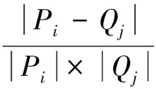

3.4 Describing images
3.5 Obtaining discriminant function
3.6 Recognizing landmarks online
4 Robot Navigation
4.1 Navigation arithmetic
4.2 GPU acceleration during image processing
5 Experimental Results
5.1 Experimental environment
5.2 Specific experiments
6 Conclusions and Future Work
Acknowledgment
 CAAI Transactions on Intelligence Technology2017年4期
