
Optimal design for split-and-recombine-type flow distributors of microreactors based on blockage detection☆
2016-05-30 12:54LinWangXianzuoKongYongshengQi
Lin Wang*,Xianzuo Kong,Yongsheng Qi
Department of Control Engineering,Inner Mongolia University of Technology,Huhhot 010080,China
1.Introduction
Chemical reactions happen faster at microscale as a result of faster mass transfer and efficient heat transfer.The low hold-up in microreactors can offer excellent controllability,reduce safety risks and result in cheaper and more environmentally friendly operation[1].Commercially available microreactor products for the industry are however limited.In order to realize microreactors with high throughput,the parallelization of microreactors,i.e.,numbering-up technology is an effective approach.In these scale-out structures the challenge is to keep satisfactory uniformity in the fluid distribution among microreactors[2].With the size limitation of microreactors,it is not practical to install sensors in each microreactor when parallelization structures are adopted.Therefore,another critical problem is how to detect the blockage abnormal condition which is the most recognized trouble in microreactors[3].
It is not a trivial thing to keep the desired transport and reaction characteristics previously achieved in one single microchannel during the numbering-up process.Therefore,the design of proper fluid distributors to guarantee uniformity flow distribution among parallelized microchannels is very important.Saber et al.proposed multi-scale microreactor networks for numbering-up process and analyzed the impact of flow uniformity on the microreactor performances[4].For one-scale microreactors,different distributors have been developed toward solving this problem.Mostofthese distributors fallinto one oftwo categories:manifold-type(see Fig.1)and bifurcation-type(Fig.2)[5].In the manifold-type distributor research,Grif fini and Gavriilidis built a two-dimensional and a three-dimensional computational fluid dynamics(CFD)model[2],and found that the flow distribution chambers'length and shape,and plate width and inlet/outlet location are the most important parameters that in fluence the uniformity of microchannels.Commenge et al.built an approximate pressure drop model to realize the optimal design for flow uniformity in microreactors[6].In the bifurcation-type research,Yue et al.investigated the flow distribution and mass transfer characteristics of gas–liquid flow in a parallelized microchannel contactor integrated with two designed distributors numerically and experimentally.A nearly uniform gas–liquid distribution at high gas flow rates can be ensured[7].Tonomura et al.proposed a new type of distributor named as“split-and-recombine-type flow distributors(SRFDs)”which was composed of three or more bifurcation points and one or more junction points[8].Tanaka et al.examined the flow uniformity in SRFDs by CFDsimulation in the wide range ofRef.[5].

Fig.1.Manifold-type distributors.
Blockage in microreactors causes poor uniformity in the residence time distribution among microreactors and degrades product quality.Therefore,a blockage detection system is indispensable.Kano et al.[3]developed the data-based and model-based blockage detection systems to identify a blockage in stacked microreactors from the output signals of temperature changes.Yamanoto et al.[9]proposed a pressure balance model to locate channel blockage and estimate the degree of blockage.Tanaka et al.[5]investigated the effect of sensor location and sensor number on the proposed blockage detection system based on SRFDs.The above blockage diagnosis systems are useful to cope with an abnormal situation in which blockage occurs at only one microreactor.Noda et al.[10]proposed a data-based blockage diagnosis system that can identify blockage in two microreactors by using fewer pressure sensors.When a blocked microreactor is identified,production can be continued by replacing it with a new one instead ofreplacing the whole numbering-up microreactors.Tonomura etal.[11]developed the effective operation and controlmethod for parallelized microreactors to keep the flowrates at a desired value even when blockage occurs.
In thisresearch,a simple modelthatintegrated the massbalance and pressure balance equations of SRFDs is proposed.The model accuracy is verified by experimental data.In a case study,an optimal design problem of SRFDs is solved to assess the flow uniformity and the effectiveness of blockage detection.The optimum results of SRFDs are verified by 3D CFD simulation results when constant flow rate operation is adopted.Based on the optimum results of SRFDs,the pressure drop relationship between SRFD section and microreactor section is analyzed.
2.Flow Distribution in Parallelized Microreactors
This section shows the basic structures and characteristics of SRFDs with parallelized microreactors.

Fig.2.Bifurcation-type distributors.
2.1.Split-and-recombine-type flow distributors(SRFDs)
For increasing the production capacity of microreactors,the parallelization of the identical microreactors is indispensable.The parallelized microreactors are connected to flow distributors section.The distributed reactant flows enter into the microreactors and the product is collected.
Unlike manifold-type and bifurcation-type distributors,Fig.3 shows an example of SRFDs,in which one flow is divided into four flows.The SRFDs consist of vertical channels s(i,j)which have a length of L2[mm],a radius of Rs(i,j)[mm]and horizon channels c(i,j)which have a length of L1[mm]and a radius of Rc(i,j)[mm].In the outlet of SRFDs,the microreactors with a length of LR[mm]are paralleled.F[mm3·s−1]is the volume flow rate of each channel.The outlet of microreactors is opened to atmosphere.Using SRFDs,the uniform flow distribution in microreactors can be obtained even when the inlet flow rate or the material properties of the reactants change.
Fig.3.Split-and-recombine-type flow distributors.
2.2.Models of SRFDs
Although calculation of the fluid velocity distribution over the entire SRFDs and microreactors is possible with existing CFD packages,a complete simulation of whole geometries requires large computer resources.The present study concerns the optimal size of SRFDs,and thus CFD simulations for a large number of different geometries have to be executed.For engineering practice and optimization,an approximate model for SRFDs and the numbering-up microreactors are built.Mass balance and pressure balance equations are applied in this model.
Mass balance equations in the SRFD section:
Split part

Elbow part


Combine part

where F is the flow rate[mm3·s−1]and N is the number of parallelization microreactors.To simplify the present analysis,the junction effects are neglected in comparison to the pipe pressure drop.Applying the Poiseuille law,the frictional pressure balance equation in SRFD section is:

The pressure balance equation between SRFD section and microreactors is:
In this study,the channel length L1is assumed to be equal to L2.
2.3.Validation of experiment data
In the experiment,L1=L2=120 mm and Rc=Rs=RR=0.8 mm.LRis designed to satisfy the pressure drop relationship between SRFDs(ΔPS)and microreactors(ΔPM).Fc(1,1)=90 mm3·s−1.Fig.4 indicates the difference between the experiment data which was carried out by Tanaka et al.and the calculation results of the model.It can be seen that there is little difference between the calculation results of the model and those of experiment.In the normal condition(ΔPSRFDs=3282.37 Pa and ΔPM=6716 Pa),the flowrate of each microreactor is shown in Table 1 and the flow uniformity in microreactors is realized.

Fig.4.Comparison between experiment data(dark blue)and the model results(pink).(Number:blockage microreactor).

Table 1 Flowrate of each microreactor in normal condition
3.Optimal Design of SRFDs
Because the diameter of microreactors is less than 1 mm,blockage is a serious problem that limits the industrial usage of microreactors.In this research,just using few sensors,a blockage detection system can cope with an abnormal situation in which blockage occurs in one microreactor based on the optimal size of SRFDs.
The built models Eqs.(1)–(6)are used to solve the optimal design problem.For the optimal design of SRFDs,the channel diameters,Rcand Rs,are selected as design variables.For example,when N parallelization microreactors with two sensors are studied,the proposed detection system uses the flowrate differences between normal and blockage conditions at one sensor(ΔFsen1)to those at another sensor(ΔFsen2).Using the built models,the blockage happens sequentially in microreactors andcan be derived.For a real parallelized microreactor system,after blockage is detectedthe blockage microreactor α is identified by the microreactor that has the smallest angle between the model valueand the actual value
In the model,the angleθi,j(i=1,…,N −1;j=i+1,…,N)between the model valueis defined as:

Based on the above description,if the angle θi,jis not big enough,the identification of the blockage microreactor is difficult because the angle difference betweenandis small.Therefore,the objective of this research is to maximize the angle θi,j.The design formulation of SRFDs is defined as follows:
The volume flow rate is set to be constant,and the size limitations of Rcand Rs∊[0 mm,5 mm]are also introduced.Meanwhile,the uniformity flow distribution in normal condition is also required.Tanaka et al.have pointed out that the ratio of two flow velocity differences remains unchanged even ifthe degree ofblockage varies.Therefore,the angleθi,jfor various degrees ofblockage should be the same.Moreover,the numberofsensors is defined as follows:Nmin≤sensornumber≤Nmax,Nminis 2 in order to calculate the angleθi,j,and Nmaxis equalto halfofthe number of microreactors because of the symmetry of SRFDs.The performance of the developed system is evaluated with its application to four and eight parallelized microreactors in the following section.
4.Case Studies
The optimal design problem of SRFDs is applied to blockage diagnosisproblems ofthe parallelized microreactors.SAmethod is used foroptimization.The optimization results are verified by CFD simulation results.In this research,the commercial CFD software ANSYS 12.0 FLUENT is used to build a real process.
4.1.Application to four parallelized microreactors
The model of SRFDs is applied to blockage diagnosis problems of the four parallelized microreactors when two sensors are selected.In the model,as shown in Fig.3,Rc(i,j)(i≠3,j≠2,i=1,2,…,N;j=1,…,i;)=Rs(i,j)(i=1,2,…,N−1;j=1,…,2i;)=R1,Rc(3,2)=R2.L1=L2=100 mm,LR=300 mm,RR=0.5 mm and Fc(1,1)=1000 mm3·s−1.The blockage condition is set to be RRb=0.8 × RRin each microreactor sequentially.
In SA,R1,R2and two sensor locations are set to be optimal variables.Moreover,the sensorlocation issetto be random in the formof sen=[0 1 0 0 1 0…0],ateach T iteration,the location of“1”is changed,buteach sen has only two of“1”.In the calculation,R1,R2and two sensor locations(sen1,sen2)are solved simultaneously by SA.A sketch of SA is explained by the following informal description[12,13].
where xiis the original state,γ is a random in(0,1)and mmaris a constant searching step when a certain length of the Markov chain lm is selected.In this method,an adaptive mmaris proposed to improve the reliability of global minimum.
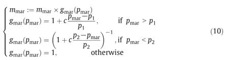
where Pmaris the acceptance ratio for a certain lm.When Pmar>P1,the searching neighborhood should be increased because too many new states are accepted.When Pmar<P2,the searching neighborhood should be decreased because the new states are close to the minimum.When P2≤Pmar≤P1,the proper mmarcan be used continuously.For sennew,the first two maximum values are set to be “1”and the others are “0”.
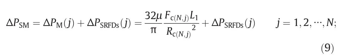
From the optimization results,the maximum angle difference is 83°when R1=2.8 mm,R2=2.05 mm and the two sensors mounted in channels c(3,2)and s(1,2).The results of flow rate measurements in the model and in the CFD verification simulation(see Fig.5)are plotted in the two-dimensional ΔFc(3,2)and ΔFs(1,2)space.The uniformity flowrate of each microreactor is shown in Table 2.In Fig.6,it is clarified that the blockage location is successfully identified on the basis of the angle of two flow rate differences.Meanwhile,the pressure drop relationship between SRFD section(ΔPSRFDs)and microreactor section(ΔPM)is analyzed.In this case study,the ratio ΔPSRFDs/ΔPSM,is 0.995.ΔPSMis defined as the pressure drop from the inlet to each outlet of the SRFDs.the pressure drop in SRFD section is much lower than that of the microreactor section.
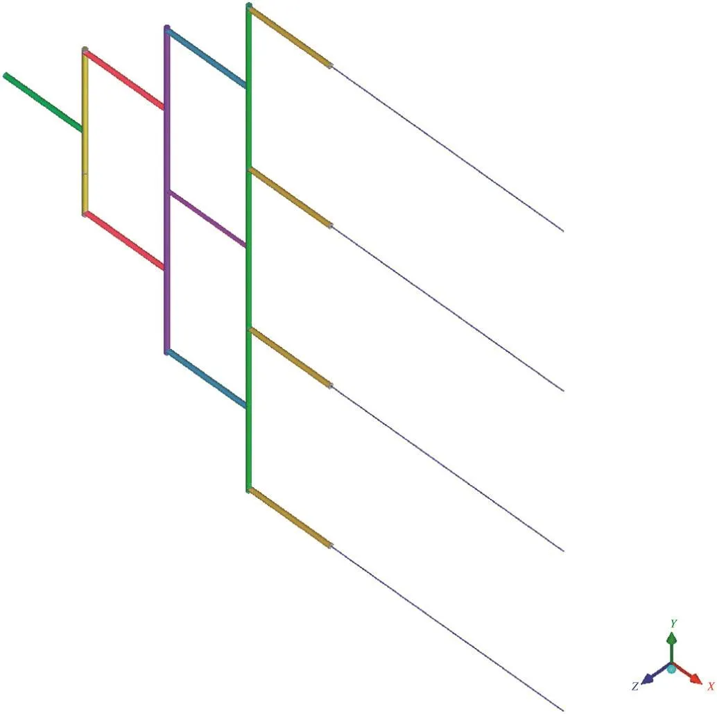
Fig.5.Geometry of four parallelized microreactors for CFD simulation.
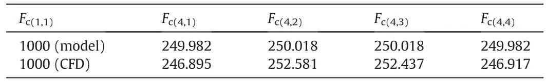
Table 2 Flowrate of each microreactor in normal condition

Fig.6.Comparison of optimal design results of CFD simulation(pink)and the model results(dark blue).

Fig.7.Split-and-recombine-type flow distributors for 8 parallelized microreactors.
4.2.Application to eight parallelized microreactors
The optimal design problem of SRFDs is applied to blockage diagnosis problems of the 8 parallelized microreactors(see Fig.7)when two sensors are selected.
In the model,Rc(5,j)(j=1,…,5)=R1,Rc(6,j)=R(6,j)(j=1,…,6),Rc(7,j)=R(7,j)(j=1,…,7),and the other Rc(i,j)(i≠5,6,7;i=1,2,…,N;j=1,…,i;)=Rc,Rs(i,j)(i=1,2,…,N − 1;j=1,…,2i;)=Rs.L1=L2=100 mm,LR=300 mm,RR=0.5 mm and Fc(1,1)=1000 mm3·s−1.The blockage condition is set to be=0.8×RRin each microreactor sequentially.
From the optimization results,the maximum angle difference is 40°when R1,R(6,j)(j=1,…,6)and R(7,j)(j=1,…,7)are equal to the values that are shown at the right side of Fig.8.Rc=3 mm,Rs=3 mm and the two sensors are mounted in channels c(6,2)and c(6,5)(red star location in the right side of Fig.8).The results of flowrate measurements in the model are plotted in the two-dimensional ΔFc(6,2)and ΔFc(6,5)space at the left side of Fig.8.It is clarified that using the two sensors can detect the blockage location in 8 parallelized microreactors,but the fabrication of the multi-scale(16 types of radius)pipes in SRFDs should be difficult.
The optimal design problem of SRFD is applied to the blockage diagnosis problems of the 8 parallelized microreactors(see Fig.9)when three sensors are selected.In the model,Rc(6,3)=R1,Rc(6,4)=R2,Rc(7,4)=R3and the other Rc(i,j)(i=1,2,…,N;j=1,…,i;)=RcRs(i,j)(i=1,2,…,N−1;j=1,…,2i;)=Rs.L1=L2=100 mm,LR=300 mm,RR=0.5 m,and Fc(1,1)=1000 mm3·s−1.The blockage condition is set to be=0.8×RRin each microreactor sequentially.The three sensors are selected to locate in the shadow part of SRFDs.

Fig.8.Optimal design results of the 8 parallelized microreactors model with two sensors.
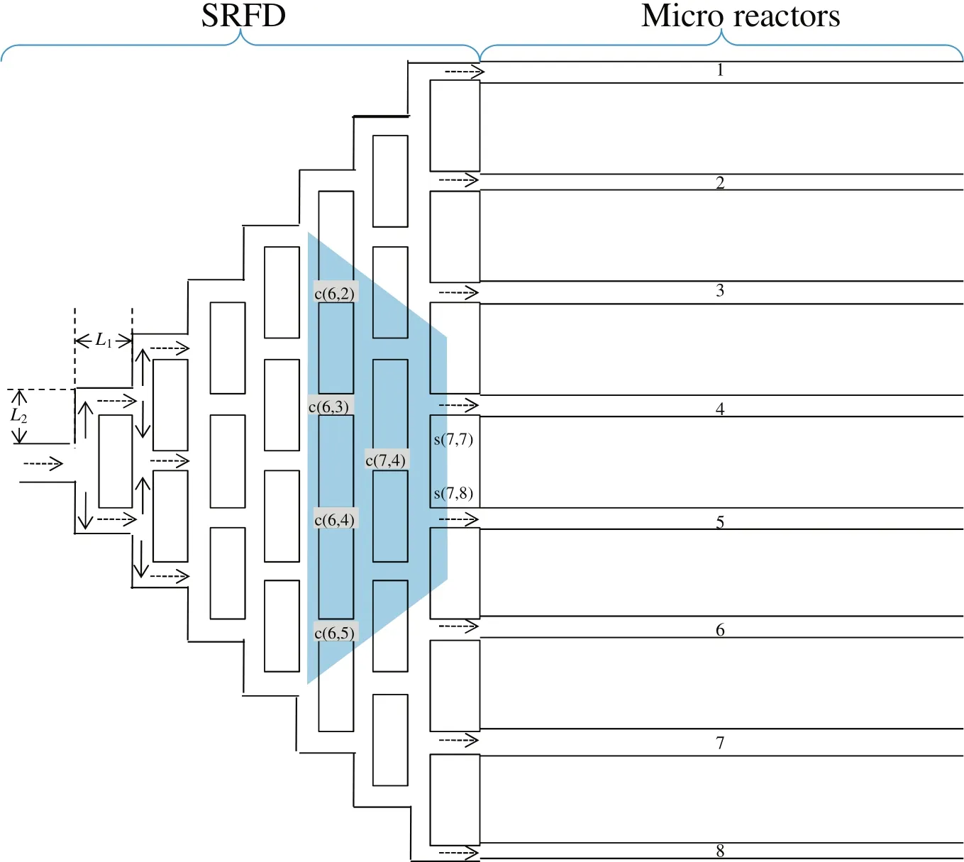
Fig.9.Split-and-recombine-type flow distributors for 8 parallelized microreactors.
From the optimization results,the maximum angle difference is 26°when R1=1.37 mm,R2=1.16 mm,R3=1.23 mm,Rc=5.08 mm,Rs=2.78 mm and the three sensors mounted in channels c(6,2)and c(6,3)or channel c(6,5).The results of flow rate measurements in the model are plotted in the three-dimensional ΔFc(6,2),ΔFc(6,3)and ΔFc(6,5)space in Fig.10.It is clarified that using the three sensors to detect the blockage location in 8 parallelized microreactors is feasible.In addition,compared to the case study of using two sensors for 8 parallelized microreactors,although the fabrication of 5 type radius pipes in SRFDs should not be difficult,the maximum angle difference becomes small and the blockage location detection becomes a bit difficult.
5.Conclusions
In this research,a simple model that integrated the mass balance and pressure balance equations of SRFDs is proposed.The model accuracy is verified by experimental data.In case studies,the optimal design of SRFDs can not only effectively realize the blockage detection with few sensors,but also realize the flow uniformity in normal conditions.
When constant flow rate operation strategies are adopted for SRFDs and microreactor system,the blockage detection can be realized with few flow rate sensors when using the optimum radius of SRFDs.The optimal design results are verified by 3D CFD simulations.Meanwhile,the optimal design results suggest that the pressure drop of the parallelized microreactor section is considerably bigger than that of the SRFD section.
Nomenclature
F flow rate,mm3·s−1
L length of each pipe,mm
lm the length of Markov chain
m searching step
p probability of acceptance ratio
R radius of each pipe,mm
sen sensors

Fig.10.Optimal design results of the model results.
γ a random value
θ angle,(°)
μ viscosity,Pa·s
Superscripts
b blockage
Subscripts
c horizon channels
R microreactors
SM SRFD section+microreactor section
s vertical channels
[1]E.R.Delsman,M.H.J.M.Croon,G.J.Kramer,P.D.Cobden,C.Hofmann,V.Cominos,J.C.Schouten,Experiments and modeling of an integrated preferential oxidation–heat exchanger microdevice,Chem.Eng.J.101(2004)123–131.
[2]G.Grif fini,A.Gavriilidis,Effect of microchannel plate design on fluid flow uniformity at low flow rates,Chem.Eng.Technol.30(2007)395–406.
[3]M.Kano,T.Fujioka,O.Tonomura,S.Hasebe,M.Noda,Data-based and model-based blockage diagnosis for stacked microchemical processes,Chem.Eng.Sci.62(2007)1073–1080.
[4]M.Saber,J.M.Commenge,L.Falk,Microreactor numbering-up in multi-scale networks for industrial-scale applications:Impact of flow maldistribution on the reactor performances,Chem.Eng.Sci.65(2010)372–379.
[5]Y.Tanaka,O.Tonomura,K.Isozaki,S.Hasebe,Detection and diagnosis of blockage in parallelized microreactors,Chem.Eng.J.167(2011)483–489.
[6]J.M.Commenge,L.Falk,J.P.Corriou,M.Matlosz,Optimal design for flow uniformity in microchannel reactors,AIChE J.48(2002)345–358.
[7]J.Yue,R.Boichot,L.Luo,Y.Gonthier,G.Chen,Q.Yuan,Flow distribution and mass transfer in a parallel microchannel contactor integrated with constructal distributors,AIChE J.56(2010)298–317.
[8]O.Tonomura,S.Nagahara,M.Kano,S.Hasebe,Fluid distribution and blockage diagnosis in parallel microchannel configurations,Proceedings of 10th IMRET/AIChE Spring National Meeting,New Orleans 2008,p.128d.
[9]R.Yamamoto,M.Noda,H.Nishitani,Blockage diagnosis of microreactors by using pressure sensors,Kagaku Kogaku Ronbunshu 35(2009)170–176.
[10]M.Noda,N.Kurihara,H.Nishitani,Blockage diagnosis of stacked microreactors using pressure sensors,Proceedings of PSE ASIA 2010,Singapore 2010,pp.413–418.
[11]O.Tonomura,T.Tominari,M.Kano,S.Hasebe,Operation policy for micro chemical plants with external numbering-up structure,Chem.Eng.J.135S(2008)S131–S137.
[12]M.Hanke,P.Li,Simulated annealing for the optimization of batch distillation processes,Comput.Chem.Eng.24(1)(2000)1–8.
[13]S.Kirkpatrick,C.D.Gelatt,M.P.Vecchi,Optimization by simulated annealing,Science 220(1983)671–680.
 Chinese Journal of Chemical Engineering2016年7期
- Chinese Journal of Chemical Engineering的其它文章
- Vanadium oxide nanotubes for selective catalytic reduction of NO x with NH3
- A unified graphical method for integration of hydrogen networks with purification reuse☆
- Theoreticalpredictions ofviscosity ofmethane under confined conditions☆
- Permeabilization of Escherichia coli with ampicillin for a whole cell biocatalyst with enhanced glutamate decarboxylase activity☆
- Formation of crystalline particles from phase change emulsion:In fluence of different parameters
- The effect of SiO2 particle size on iron based F–T synthesis catalysts