
Mixing times in single and multi-orifice-impinging transverse(MOIT)jet mixers with cross flow☆
2016-05-30 12:53PeichengLuoYuncuiTaiYiFangHuaWu
Peicheng Luo *,Yuncui TaiYi Fang Hua Wu *
1 School of Chemistry&Chemical Engineering,Southeast University,Nanjing 211189,China
2 Institute for Chemical and Bioengineering,Department of Chemistry and Applied Bioscience,ETH Zurich,8093 Zurich,Switzerland
1.Introduction
The jet mixer with cross flow is widely used in the fields of gas mixing,e.g.mixing fuel and air in gas turbine combustor,as well as in the field of liquid mixing,especially in the chemical industrial processes with parallel or consecutive competitive reactions.In the latter cases,the efficiency of reactants mixing can greatly affect the yield and selectivity of the target products when the time scales of the reactions are smaller than those of the mixing[1,2].
The mixing process in jet mixers with cross flow(or transverse jet mixing process)has been investigated widely in the past few decades.The topics range fromthe fundamentalunderstanding ofthe generation and evolution of vortex structures[3–6],to the macro-scale features of the mixing process,e.g.the fluid field distributions[7,8],jet trajectories and their correlations[8–11],the degree of unmixedness,and the mixing time[12–19].It is noted that the reported studies(in particular on the multi-orifice-impinging transverse(MOIT)jet mixers)in the literature focus mainly on gas mixing[20–22],while few can be found for liquid mixing,which is more important in practical applications in chemical industry.When the transverse jet mixer is applied to achieve effective mixing of reactants for mixing-sensitive reactions,the macromixing step(or bulk mixing)is likely to determine the product distribution of the multiple reactions[1].
For the jet mixer,the macromixing time is always calculated from the mixing uniformity along the flow direction,which mainly depends on the interaction between the jets and the cross flow,as well as the interaction among the jets in the case of multiple jets[21].The jet-tocross flow velocity ratio(or momentum ratio)and the jet mixer configuration are two main factors that affect the flow structure of the transverse jet mixing process.At low jet-to-cross flow velocity ratio,the jets always attach to the pipe wall,referred to as underpenetration of the jets.As the velocity ratio increases,the jets are detached from the pipe wall and start to penetrate deep into the cross flow.When the velocity ratio reaches a certain value for the single jet mixer,the jet begins to hit the opposite pipe wall,whereas for the MOIT jet mixer,the jets collide with each other in the center of the mixing pipe.When the impingement is intensive enough,part of jet(or jets)will go upstream above the jet injection plane,referred to as back-splash in our previous study[23].Recently,Kartaev et al.also observed the back-splash in the region upstream the side jets in the gas mixing process[24].Such back-splash will prolong the mixing process,thus not bene ficial for the mixing-sensitive reactions.However,in the literature the emphasis is always on the downstream mixing process,and little information can be found on how the back-splash in the upstream affects the mixing performance.
The main objective in this work is to carry outdetailed investigations on the macro-mixing behaviorofthe liquid fluids in the single and MOIT jet mixers.In particular,we focus on the study of the dimensionless overall mixing time and how the back-splash affects it.The mixing time is calculated based on the spatial variance and the temporal variance of concentration distribution obtained by using the non-invasive planar laser-induced fluorescence(PLIF)technique.We determine the conditions in which the back-splash occurs in the mixer with different configurations(e.g.the mixing pipe diameter,the diameter and number of the side jets),and the effect of the back-splash on the overall mixing time.
2.Experimental
2.1.Con figuration parameters of the jet mixer
Fig.1 shows schematically the configuration of the jet mixer.It consists of a mixing pipe,on which one(single jet mixer)or several identical orifices(MOIT jet mixer)embedded on the pipe wall symmetrically and perpendicularly,and a rectangular buffer chamber around the mixing pipe.Stream A flows along the mixing pipe.Stream B enters the buffer chamber first,then being divided into equal sub-streams and injected into the mixing pipe from the orifices.The origin of the reference frame is the cross sectional plane perpendicular to the y axis( flow direction)through the center of the orifices.In this work,we varied the diameters of both the mixing pipe(D,from 16 to 40 mm)and injecting orifices(d,from 4 to 10 mm),and the number of the orifices(n,from 1 to 4),to investigate their effect on the mixing performance of the process.The mixer is named as M D-nΦd,e.g.a mixer with name,M16-2Φ4,has 2 orifices(4 mm in diameter)on the mixing pipe(16 mm in diameter).We have investigated 6 jet mixers with different configuration parameters,as listed in Table 1.

Fig.1.Setup of the jet mixer.(a)Overview of the mixer configuration and(b)cross sectional plane perpendicular to the y axis( flow direction)through the center of the orifices.

Table 1 Con figuration parameters of the jet mixers
2.2.Flow conditions of the mixing process
The flow conditions of different runs for each mixer are listed in Table 2.The Reynolds number of both the jet flow in the orifices(Rej,from 3500 to 34900)and that in the pipe(Rec,from 4200 to 17500)has been designed to ensure they are all in the turbulent regime,which is also a generalinterestin the literature[21].Since the two fluids have the same density,the jet-to-cross flow velocity ratio,r,is particularly suitable to characterize the flow field of the transverse jet[22].

where ujand ucare the velocities of Stream B in the jet and Stream A in the pipe,respectively.In addition,the flow rate ratio,RF,may be defined as

where QBand QAare the flow rates of Stream B and Stream A,respectively.The RFvalue shows directly the amount of the two liquids to be mixed.
2.3.Measurement of the mixing process by PLIF technique
The mixing process in the jet mixer was studied using the 2-D noninvasive planar laser induced fluorescence(PLIF)technique.In all the experiments tap water was used for both Streams A and B,and Stream A contained Rhodamine 6G as the tracer for the PLIF experiment.Both liquids were pumped into the mixer at desired flow rates using two gear pumps.The entire fluid in the pipe was excited by a continuous laser with the wavelength of 532 nm(Kinder™Optronics,KDPSL-3W),and the emitted fluorescence light was captured by a highsensitive CCD camera(Baumer,TXG14NIR)with the image size of 1392×1040 pixels.The distribution of fluorescence intensity in the measurementplane can be converted to the tracer concentration distribution.Detailed setup of the experimental system and the calibration procedure can be found in our previous work[23].
3.Results and Discussion
3.1.Temporal and spatial unmixedness of the process
The mixing process was visualized by pseudo-color images converted from gray-level images of the PLIF experiments.In this work,the initial dimensionless concentrations of Stream B(jet flow)and Stream A(cross flow)are set to be one and zero,respectively.Fig.2 shows instantaneous and time-averaged mean concentration of the mixing process in the mixers,M16-1Φ8 and M16-2Φ5.6.In turbulent flow,the local instantaneous concentration,ft,loc,can be described by the time-averaged mean concentration,ft,loc,plus the temporal fluctuation of the local concentration,ft′,loc,i.e.,

When two streams are mixed,two common indices to evaluate the mixing state are the spatial and temporal unmixedness indices[25].In general,the spatial unmixedness index is calculated from the timeaveraged mean concentration distribution,whereas the temporal unmixedness index considers turbulent fluctuation of the local concentration.In our previous work[23],the mixing process was evaluated by the spatial variation of concentration within the defined mixing region.In this work,we make a further comparison between these two indices to find which one is more appropriate,in particular in the evaluation of the turbulentmixing process represented by the instantaneous concentration distribution.
The spatial unmixedness index,Ispat,was calculated based on the time-averaged mean concentration distribution.At the defined mixing zone with m sub-zones,Ispatis
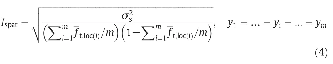
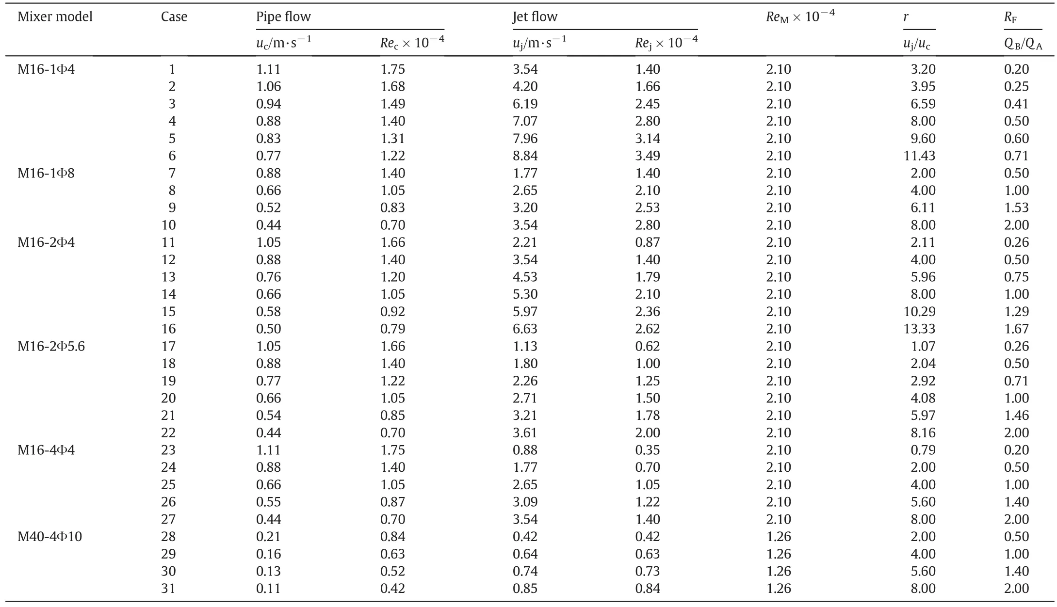
Table 2Flow conditions of the mixing process
where σsis the spatial variance of the concentration within the defined mixing zone.The quantity,Ispat,represents the extent to which the concentration in different sub-zones of a cross section perpendicular to the main flow direction departs from the mean concentration.

Fig.2.Effect of the configuration parameters on the time-averaged mean[(a)and(c)]and instantaneous[(b)and(d)]concentration distribution.r=2.0;Re M=2.10×10⁴.(a)and(b)M16-1Φ8;(c)and(d)M16-2Φ5.6.
The local temporal unmixedness index at a certain spatial point of(x,y,z),Itemp,loc,can be evaluated by the temporal variance,σt,loc,based on the mixing index definition proposed by Danckwerts[26]:
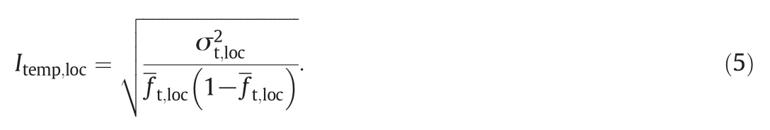
In this work,we focus on the mixing extent at a certain streamwise position(y)in the mixing pipe.Thus,the averaged temporal unmixedness index,Itempis calculated based on all the sub-zones which have the same y coordinate,to describe the mixing state,i.e.,

As defined by Eqs.(4)and(6),the unmixedness index equals 1.0 when two streams are completely segregated and 0.0 when they are mixed uniformly.In this work,the values of temporal and spatial unmixedness indices in the flow direction were calculated to evaluate the mixing extent.
Fig.3 shows a comparison of Itempand Ispattrends for the mixers,M16-1Φ8 and M16-2Φ5.6,under the same flow conditions.It can be seen that the spatial unmixedness index,Ispat,decreases sharply in the flow direction,whereas the temporal unmixedness index,Itemp,increases at the beginning of the mixing process,and after reaching a maximum value,it decreases gradually.This is because that Itempis defined based on the temporal variance of the local concentration.From Fig.2(b)one can see that two streams are segregated in the initial dozens of millimeters in y direction,i.e.,the temporal variance in the segregated bulk of both Streams A and B are very low,thus leading to a minimum Itempvalue when y=0 and a subsequent increase of the Itempvalue as the segregated bulk disappears gradually.From this point of view,Itempis not a proper index to evaluate the mixing state when there exists segregated bulk in the mixed stream.However,when the segregated bulk nearly disappears(y=~20 mm for the mixer,M16-1Φ8),Itempcomes to a maximum value.Then the uniformity begins to increase and Itempdecreases gradually.

Fig.3.Trends of the temporal and spatial unmixedness indices(I temp and I spat)for the mixers,M16-1Φ8 and M16-2Φ5.6.r=2.0;Re M=2.10×10⁴.
From Fig.3 we can see that in the mixer,M16-1Φ8,Itempreaches a value of 0.1 at y=95.9 mm,whereas Ispatreaches the same value at y=37.1 mm.It is noted that the unmixedness indexes defined by Eqs.(4)and(5)correspond to the square root values of the original unmixedness index defined by Danckwerts[26],i.e.,I=0.1 represents a unmixedness index of 1%based on the Danckwerts definition(a 99%uniformity of mixing)[26].Examining the instantaneous concentration distribution in Fig.2(b)at Ispat=0.1,there still exist big clusters of unmixed fluid A at y=37.1 mm,i.e.,the mixing process has not yet reached the final state.Instead,the value of Itemp=0.1 properly characterizes the mixing state,where one can see that the mixing process has approached a nearly finished point at~90 mm in y direction.For the other mixers studied in this work,we also find that Itempis a more appropriate index than Ispatto characterize the mixing state,in particular in evaluating the macromixing behavior of the whole process.Thus,in the following,we define the mixing time by using the temporal unmixedness index,Itemp.
3.2.Dimensionless overall mixing time and back-splash mixing time
For the mixing process in the transverse jet mixer,the flow patterns depend strongly on the interaction between the main stream and jets.When the jet-to-cross flow velocity ratio,r,is relatively small,the mixing process mainly occurs downstream(as shown in Fig.2).In this case the mixing performance can be intensified by increasing the r value[23].When r increases to a certain value,direct impingement between the jet and the wall in the single jet mixer[Fig.4(a)]or among the jets in the MOIT jet mixer[Fig.4(b)]will occur,leading to back-splash.
It is noted that the back-splash prolongs the whole mixing process.To evaluate the effect of the back-splash,we define the back-splash mixing time,τb,and the overall mixing time,τ,as follows:
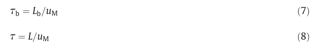

Fig.4.Back-splash in the mixers,(a)M16-1Φ4 and(b)M16-4Φ4,and(c)the illustration of the overall mixing length and back-splash mixing length of the process.r=8.00;Re M=2.10×10⁴.
where uMis the mean velocity of the mixed fluid exiting the mixing pipe,Lb,as shown in Fig.4(c),is the distance from the injecting point of Stream B to the upstream point where the back-splash clusters and Stream A have reached the mixing state,Itemp=0.1,and L is the distance from the upstream point where Itemp=0.1(possibly the place back-splash reaches)to the downstream point where the two fluids have reached the same mixing state,Itemp=0.1.Thus,from the definition,the back-splash occurs for all the values of Lb>d/2.The dimensionless overall mixing time,θ,and the dimensionless backsplash mixing time,θb,are defined as the mixing length scaled by the diameter of the mixing pipe:

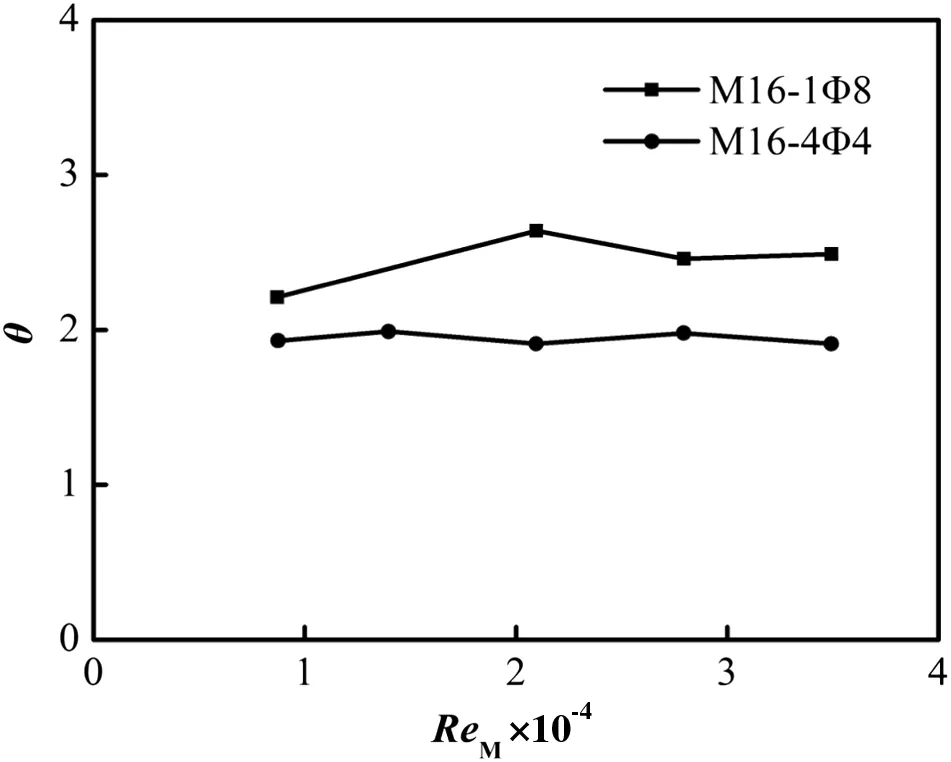
Fig.5.Effect of Re M on the dimensionless mixing time.r=4.
We first keep the velocity ratio,r=4,for the mixers M16-1Φ8 and M16-4Φ4,where no obvious back-splash was observed(data not shown),to investigate the effect of ReMon the dimensionless overall mixing time.As shown in Fig.5,the θ values do not change significantly with ReMin these cases.In cases of the occurrence of back-splash,the change of dimensionless overall mixing time is generally no more than 10%when ReMvaries from 1.0×10⁴to 3.5×10⁴for all mixers studied in this work.Then,we fixed ReMand changed the velocity ratio,r.Fig.6 shows the θ and θbvalues as a function of the velocity ratio,r.It is seen that there is a critical velocity ratio,rc,for each mixer.When r< rc,θbis relatively low and changes insignificantly with r.When r> rc,θbincreases sharply as r increases,which implicates that the impingement becomes more and more intensive.For the single jet mixer[see Fig.6(b)],in the region of very high r values,the increase rate ofθbwith r decreases.Instead,for the MOIT jetmixers[see Fig.6(d)and(f)]in the same r range,θbincreases almost linearly with r.This linear relationship between r and θbhas also been found by Kartaev et al.[24]for the gas mixing in the MOIT jet mixer when the back-splash occurs.
From Fig.6 we can see that the dimensionless overallmixing time,θ,reaches either a plateau[M16-1Φ4 in Fig.6(a),M16-2Φ4 in Fig.6(c),M40-4Φ10 in Fig.6(e)]or a local minimum[M16-1Φ8 in Fig.6(a),M16-2Φ5.6 in Fig.6(c),M16-4Φ4 in Fig.6(e)]and then increases slightly again with r.The minimum r value to reach the plateau or the r value at the local minimum is here defined as the optimal velocity ratio,ropt,because it corresponds to the smallest dimensionless overall mixing time,θ.In Fig.7 are reported for each mixer the critical velocity ratio value,rc,and the optimal velocity ratio,ropt,defined above.It can be seen that rcis always smaller than or equal to ropt.This is because the overall mixing time is practically determined by the downstream mixing in the pipe when r<rc,and in this case the overall mixing time decreases(or mixing intensification increases)as r increases.When the back-splash occurs,this intensification of the downstream mixing will be offset by the prolongation of the upstream back-splash mixing time,θb.If the prolongation of θbplays a dominant role,θ would reach a minimum value at rc=ropt(e.g.M16-4Φ4).Instead,when the intensification of the downstream mixing plays a dominant role,θ would continue decreasing with r,i.e.,rcwould be smaller than ropt.
3.3.Effect of the configuration parameters

Fig.6.The dimensionless overall mixing time and the dimensionless back-splash mixing time.Re M=2.10×10⁴(Re M=1.26×10⁴ for the mixer of M40-4Φ10).

Fig.7.Effect of the configuration parameters on the critical velocity ratio and the optimal velocity ratio.
Besides the flow conditions,the mixer configuration is another factor affecting the mixing performance.Fig.7 shows the effect of the configuration parameters on rcand ropt.Itis known thatthe momentum ratio between the jet and the cross flow plays a key role in the mixing performance[27–29].The expression for the momentum ratio of Stream B to Stream A,MB/MA,is
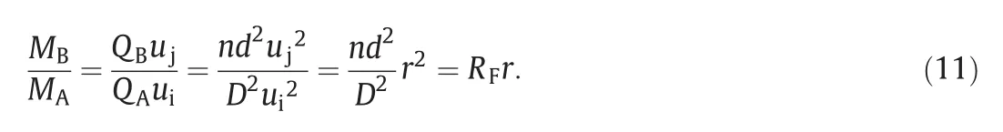
To check the effect of the configuration parameters(n,d,and D)included in Eq.(11),we first keep the diameter of the mixing pipe constant(D=16 mm)and change the orifice diameter or the number of the orifices.In this case,both rcand roptdecrease as n increases[Fig.7(a)]or as d increases[Fig.7(b)].However,when the overall area of the injection orifices(=nπd2/4)is fixed,as shown in Fig.7(c),the rc(or ropt)value is almost constant even though n and d are changed.This indicates that the mixing of the injected streams through orifices with the transverse streams is determined by the momentum ratio.
From Eq.(11)it seems that at the given r value,the mixing process will be similar when the values of d/D and n are fixed.To check this point,we have kept d/D=0.25 and n=4,and scaled up the jet mixer from M16-4Φ4 to M40-4Φ10.As shown in Fig.6(e),the minimum values of the overall mixing time are indeed almost the same.However,the rcand roptvalues have increased from 4 to 5.6[see Fig.7(d)].This implicates that higher momentum is required to achieve the optimalmacromixing fora largerscale mixer.From Eq.(11)itcan be seen thatwhen the flowrate ratio(RF=QB/QA)keeps constant,one can increase the momentum ratio by reducing the area ratio of all the injection orifices to the cross section of the pipe(i.e.r increases).Specifically,when D is scaled up from 16 mm to 40 mm,the orifices should be designed as d=8.5 mm(corresponding to r=5.6)instead of d=10 mm(corresponding to r=4)in the case of n=4 and RBF=1,to achieve the optimal macromixing with the minimum θ value as that of the mixer,M16-4Φ4.
4.Conclusions
A further study of the macromixing behavior of two liquids in single jetmixers and multi-orifice-impinging transverse(MOIT)jetmixers has been carried out,in particular,in terms of the dimensionless mixing times.The overall mixing time and the mixing time caused by the back-splash are calculated based on the spatialvariance and the temporal variance of the concentration distribution obtained by using the PLIF technique.
It is found that the temporal unmixedness index,Itempcalculated from turbulent fluctuations of the local concentration,is a more appropriate index to describe the turbulent mixing state than the spatial unmixedness index,Ispat.
When the mixer configuration is fixed,there is a critical jet-tocross flow velocity ratio,rc,at which the back-splash begins to occur,leading to sharp increase of the back-splash mixing time,θb.The latter can partly offset the intensification of the downstream mixing.The dimensionless overall mixing time,θ,decreases as r increases to reach either a plateau or a local minimum.The corresponding r value represents the optimal velocity ratio,roptof the macromixing.The rcvalue is always smaller than or equal to the roptvalue.
It has been noticed that the momentum ratio of the two liquid fluids is a dominantfactorcontrolling the macromixing behavior,in particular,rcand ropt.In addition,a higher momentum is required to achieve the optimal macromixing with the minimum θ for a larger scale mixer.
[1]J.R.Bourne,Mixing and the selectivity of chemical reactions,Org.Process.Res.Dev.7(4)(2003)471–508.
[2]E.L.Paul,S.M.Kresta,V.A.Atiemo-Obeng,Handbook of industrial mixing:Science and practice,Wiley-Interscience,Hoboken,New Jersey,2004.
[3]B.A.Haven,M.Kurosaka,Kidney and anti-kidney vortices in cross flow jets,J.Fluid Mech.352(1997)27–64.
[4]S.H.Smith,M.G.Mungal,Mixing,structure and scaling of the jet in cross flow,J.Fluid Mech.357(1998)83–122.
[5]R.M.Kelso,A.J.Smits,Horseshoe vortex systems resulting from the interaction between a laminar boundary layer and a transverse jet,Phys.Fluids 7(1)(1995)153–158.
[6]R.M.Kelso,T.T.Lim,A.E.Perry,New experimental observations of vortical motions in transverse jets,Phys.Fluids 10(9)(1998)2427–2429.
[7]G.Pan,H.Meng,Experimental study of turbulent mixing in a tee mixer using PIV and PLIF,AICHE J.47(12)(2001)2653–2665.
[8]M.Gordon,J.E.Cater,J.Soria,Investigation of the mean passive scalar field in zeronet-mass- flux jets in cross- flow using planar-laser-induced fluorescence,Phys.Fluids 16(3)(2004)794–808.
[9]S.Muppidi,K.Mahesh,Study of trajectories of jets in cross flow using direct numerical simulations,J.Fluid Mech.530(2005)81–100.
[10]L.L.Yuan,R.L.Street,Trajectory and entrainment of a round jet in cross flow,Phys.Fluids 10(9)(1998)2323–2335.
[11]L.J.Forney,Z.Feng,X.Wang,Jet trajectories of transverse mixers atarbitrary angle in turbulent tube flow,Chem.Eng.Res.Des.77(A8)(1999)754–758.
[12]C.Cozewith,M.Busko,Design correlations for mixing tees,Ind.Eng.Chem.Res.28(10)(1989)1521–1530.
[13]P.Manjula,P.Kalaichelvi,K.Dheenathayalan,Development of mixing time correlation for a double jet mixer,J.Chem.Technol.Biotechnol.85(1)(2010)115–120.
[14]J.D.Holdeman,D.S.Liscinsky,V.L.Oechsle,G.S.Samuelsen,C.E.Smith,Mixing of multiple jets with a confined subsonic cross flow.I.Cylindrical duct,J.Eng.Gas Turbines Power 119(4)(1997)852–862.
[15]J.D.Holdeman,D.S.Liscinsky,D.B.Bain,Mixing of multiple jets with a confined subsonic cross flow:Part II—Opposed rows of orifices in rectangular ducts,J.Eng.Gas Turbines Power 121(3)(1999)551–562.
[16]J.T.Kroll,W.A.Sowa,G.S.Samuelsen,J.D.Holdeman,Optimization of orifice geometry for cross flow mixing in a cylindrical duct,J.Propuls.Power 16(6)(2000)929–938.
[17]A.T.G.Giorges,L.J.Forney,X.D.Wang,Numerical study of multi-jet mixing,Chem.Eng.Res.Des.79(A5)(2001)515–522.
[18]T.M.Muruganandam,S.Lakshmi,A.A.Ramesh,S.R.Viswamurthy,R.I.Sujith,B.M.Sivaram,Mixing of transversely injected jets into a cross flow under low-density conditions,AIAA J.40(7)(2002)1388–1394.
[19]R.M.Morris,J.A.Snyman,J.P.Meyer,Jets in cross flow mixing analysis using computational fluid dynamics and mathematical optimization,J.Propuls.Power 23(3)(2007)618–628.
[20]A.R.Karagozian,The jet in cross flow,Phys.Fluids 26(10)(2014)101303.
[21]K.Mahesh,The interaction of jets with cross flow,Annu.Rev.Fluid Mech.45(2013)379–407.
[22]A.R.Karagozian,Transverse jets and their control,Prog.Energy Combust.Sci.36(5)(2010)531–553.
[23]P.C.Luo,H.Y.Jia,C.X.Xin,G.Z.Xiang,Z.Jiao,H.Wu,An experimental study of liquid mixing in a multi-orifice-impinging transverse jet mixer using PLIF,Chem.Eng.J.228(2013)554–564.
[24]E.V.Kartaev,V.A.Emel'kin,M.G.Ktalkherman,V.I.Kuz'min,S.M.Aul'chenko,S.P.Vashenko,Analysis of mixing of impinging radial jets with cross flow in the regime of counter flow jet formation,Chem.Eng.Sci.119(2014)1–9.
[25]D.W.Guillaume,J.C.LaRue,Temporal and spatial unmixedness downstream of a plate array,Phys.Fluids 12(6)(2000)1497–1508.
[26]P.V.Danckwerts,The definition and measurement of some characteristics of mixtures,Appl.Sci.Res.Sect.A 3(4)(1952)279–296.
[27]R.J.Demyanovich,J.R.Bourne,Rapid micromixing by the impingement of thin liquid sheets.2.Mixing study,Ind.Eng.Chem.Res.28(6)(1989)830–839.
[28]Y.Cheng,Z.Liu,Y.Jin,Fast liquid jet mixing in millimeter channels with various multislits designs,Ind.Eng.Chem.Res.47(23)(2008)9744–9753.
[29]P.C.Luo,Y.Cheng,Y.Jin,W.H.Yang,J.S.Ding,Fast liquid mixing by cross- flow impingement in millimeter channels,Chem.Eng.Sci.62(22)(2007)6178–6190.
 Chinese Journal of Chemical Engineering2016年7期
- Chinese Journal of Chemical Engineering的其它文章
- Vanadium oxide nanotubes for selective catalytic reduction of NO x with NH3
- Optimal design for split-and-recombine-type flow distributors of microreactors based on blockage detection☆
- Theoreticalpredictions ofviscosity ofmethane under confined conditions☆
- Permeabilization of Escherichia coli with ampicillin for a whole cell biocatalyst with enhanced glutamate decarboxylase activity☆
- Formation of crystalline particles from phase change emulsion:In fluence of different parameters
- The effect of SiO2 particle size on iron based F–T synthesis catalysts