
Gas-liquid hydrodynamics in a vessel stirred by dual dislocated-blade Rushton impellers☆
2015-11-03 06:06FenglingYangShenjieZhouXiaohuiAn
Fengling Yang*,Shenjie Zhou,Xiaohui An
School of Mechanical Engineering,Shandong University,Jinan 250061,China
Key Laboratory of High Efficiency and Clean Mechanical Manufacture(Shandong University),Ministry of Education,Jinan 250061,China
Keywords:Stirred vessel Gas-liquid mixing Dislocated-blade Rushton impeller Power consumption Computational fluid dynamics(CFD)
ABSTRACT Towards the objective of improving the gas dispersion performance,the dislocated-blade Rushton impeller was applied to the gas-liquid mixing in a baffled stirred vessel.The flow field,gas hold-up,dissolved oxygen,power consumption before and after gassing were studied using the computational fluid dynamics(CFD)technique.Dispersion of gas in the liquid was modelled using the Eulerian-Eulerian approach along with the dispersed k-ε turbulent model.Rotation of the impeller was simulated with the multiple reference frame method.A modified drag coefficient which includes the effect of turbulence was used to account for the momentum exchange.The predictions were compared with their counterparts of the standard Rushton impeller and were validated with the experimental results.It is concluded that the dislocated-blade Rushton impeller is superior to the standard Rushton impeller in the gas-liquid mixing operation,and the findings obtained here lay the basis of its application in process industries.
1.Introduction
In the past several decades,there have been considerable efforts to improve the bacteria and cell culture efficiency.These aerobic bio-processes are mostly carried out in aqueous medium with ionic salts where the solubility of oxygen is limited.Under such circumstances,oxygen must be continuously supplied and the rate of oxygen mass transfer is a key task[1].Therefore,the desire to improve gas dispersion homogeneity has attracted many scientific researchers and engineers.
The most widely used reactor in biochemical industries to carry out the bacteria and cell cultivation operations is the stirred vessel[2,3],within which the fluids are agitated by impellers.For gas-liquid mixing,excellent gas dispersion performance is the essential requirement of the impeller.It is responsible for bubble breakup and dispersion.Many kinds of impeller exist and are continuously being invented to meet various needs.Traditionally,for the operation of gas-liquid dispersion,the standard Rushton impeller has been widely used since 1950s[4].This impeller has high volumetric gas-liquid mass transfer coefficient[5].So far,it has served as the measuring yardstick to which other types of impellers are compared[2].However,in spite of its versatility,the standard Rushton impeller is not perfect and many weaknesses have been identified.For example,the axial pumping capacity is low.It is usually not sufficient to induce the necessary bulk flow to satisfy the oxygen absorption requirements.It can only effectively disperse gas in regions adjacent to the impeller.The uniform dispersion state of gas in the stirred vessel bulk is hard to achieve.Large shear stress could be produced,which is adverse especially for the cultivation of animal cell having no protecting cell wall.Due to the sweeping action of the impeller,there are low-pressure trailing vortices at the rear of the blades.This result in great power drop after gas is introduced and the gas handling capacity is handicapped by flooding[2,6].
For the purpose of improving the gas dispersion uniformity,great efforts have been devoted to the modification of the standard Rushton impeller over the past several decades.To date,many new types of modified Rushton impellers have been developed.Through increasing the blade height and simultaneously adding perforations to the blades,Roman et al.[7]designed the perforated Rushton impeller,which has a reduced power consumption and improved oxygen transfer efficiency.Chen and Chen[8]studied the comb blade and the perforated blade disc impellers.The latter was found to have higher volumetric gas-liquid mass transfer coefficient than the standard Rushton impeller at similar power input.Warmoeskerken and Smith[9]proposed the CD-6 impeller which has concaved blade just like cutting from pipe sections.This and subsequent studies[10-12]confirmed that this impeller provides better gas-liquid mixing performance than the traditional Rushton impeller.Since then,other impellers with non- flat blades were continuously being developed.For example,the hollow half elliptical blade dispersing turbine(HEDT)was applied to the gas-liquid and gas-liquid-solid mixing in stirred tanks by Chen et al.[13].The void fraction distributions under different operating conditions,including impeller rotational speed,power input,gas flow rate and temperature,were investigated.Vasconcelos et al.[14]concluded that the best performance may be expected from retro fitted Rushton impeller with streamlined blades,which lowers the power number,results in less aerated power drop,retards impeller flooding and accordingly,are confirmed more efficient and capable of handling gas.This may attribute to the fact that impellers with streamlined blades could increase the blade curvature and alter the trailing vortices characteristics[15].
Another promising improvement of the standard Rushton impeller is the self-inducing Rushton type impeller.The mixing mechanisms were explored,and the advantages of this impeller in applications of gas-liquid-solid and gas-liquid dispersion were experimentally and numerically validated by several researchers[16-19].Bakker et al.[20-22]invented the Scaba(also named as BT-6)impeller which has vertically asymmetric blades.It was shown that this impeller has a flatter aerated power curve and can disperse more gas before flooding than impellers with symmetric blades.In addition,there are also flexible blade impellers[23-25].Compared with the rigid blade impeller,the flexible blade impeller is allowed to flex into the desired curved configurations under the action of the fluid.Unfortunately,there is no available information so far for the application of flexible blade impeller in the processes involving microorganisms.
In this work,we investigate the dislocated-blade Rushton impeller in gas-liquid mixing in a baffled stirred vessel using the experimental and CFD methods.This impeller has the same component dimensions as the standard Rushton impeller,except that the blades are mounted above and below the impeller disc alternatively.To be exact,three blades are above the impeller disc,and the bottom edge of each blade is aligned with the bottom surface of the disc.For the other three blades,they are below the disc,and their top edges are parallel to the top surface of the disc.For more details about this impeller,the readers may refer to the literature[26].
2.Stirring System
Fig.1 depicts the configuration of the stirring system studied in this paper.The impellers are the standard Rushton impeller and the dislocated-blade Rushton impeller(hereafter referred to as SRT and DRT,respectively).The stirred vessel(dia.T=0.21 m)is an elliptical bottomed cylindrical vessel with four standard baffles.The offset from baffle to the vessel wall is T/60.Tap water(density:ρl=998.2 kg·m-3,dynamic viscosity:μl=0.001 Pa·s)was used as the working liquid.For the experimental measurements of dissolved oxygen,the activated sludge effluent was employed,which has the same density and viscosity as the tap water.Air(ρg=1.225 kg·m-3,μg=1.789 × 10⁻⁵Pa·s)was introduced through a ring sparger located below the lower impeller with the flow rate of Q=0.4 and 0.6 m3·h-1.There are 94 upward-facing holes(dia.0.8 mm)on the sparger pipe with the ring diameter of 0.43 T.The other dimensions of the stirring system are given in Table 1,where B is the baffle width,Csand C1are the clearances from sparger and the lower impeller respectively to the vessel bottom,C2is the spacing between the two impellers.Five impeller rotational speeds,i.e.,N=300,400,500,600,700 r·min-1were selected.The corresponding Reynolds number is in the range of Re=ρlND2/μl=3.18-7.42 × 105.Power consumptions were measured with the AKC-215 type torque transducer(China Academy of Aerospace Aerodynamics,Beijing,China).Gas dispersion images were captured with a CCD camera(Nikon AF NIKKOR,1280×1024 pixels).

Fig.1.Schematic of the stirring system:(a)stirred tank;(b)DRT impeller.
3.Numerical Simulation
3.1.Gas-liquid mixing modelling
Gas-liquid mixing in the stirred vessel was simulated using the Eulerian-Eulerian multiphase model.Mass conservation equation for each phase is given as follows:

Liquid phase(l)and gas phase(g)are assumed to share space in proportion to their volume such that their volume fractions sums to unity in the cells domain:


Table 1 Dimensions of the stirred vessel
Momentum conservation equation for phase i is where the pressure is shared by the liquid and gas phase,τiis the liquid phase stress tensor,and F is the drag force between phases.Effects of virtual mass force and lift force are negligibly small and hence can be neglected[27,28].Drag force largely predominates in aerated stirred vessels and is given below:

where d is the bubble diameter.Here,the coalescence and breakup of gas bubbles were neglected due to the fact that the computation based on this assumption gave satisfactory predictions on the gas hold-up and flow field[28-30].A single bubble diameter of 4 mm was used according to the experimental measurement of Alves et al.[31].The drag coefficient was calculated with the Schiller-Naumann model:

Repis the modified relative Reynolds number which considers the effect of turbulence[32]:

where C is the model parameter.According to the study of Khopkar and Ranade[28],it was set to 2/9.
3.2.Turbulence modelling
The turbulent flow was modelled using the standard k-ε turbulence model.This model finds wide application in simulating the gas-liquid flow when the gas phase concentration is diluted[6,19,27,28].Transport equations for this model are well-known to the readers.For the reason of simplicity,a detailed description is omitted here.In this model,the turbulent liquid viscosity in Eq.(6)is given as follows:

where Cμ=0.09 is the model parameter.
3.3.Computational grid and modelling approach
The computational model was built using the preprocessor Gambit 2.3.A non-uniformly distributed hybrid mesh consisting of 2441981 cells was generated.32 and 40 nodes were assigned along the impeller width and length,respectively.The minimal grid length equals to 0.5 mm,which equals to 0.00625D.The maximum skewness of the mesh was less than 0.81.A similar grid resolution(970997 cells for a stirred tank with an diameter T=0.3 m and Re=4.17×10⁴)was employed by Zadghaffari et al.[33]in their study of the turbulent flow and mixing in a stirred tank driven by a Rushton impeller,and satisfactory results were obtained.This implies that the grid resolution used here is adequate to resolve the turbulent flow accurately.
Rotation of the impeller was modelled with the multiple reference frame(MRF)method.The initial velocities of the fluids,as well as gas holdup in the stirred vessel were assumed to be zero.The vessel walls,shaft,baffles,sparger and impellers were treated as non-slip boundaries with standard wall functions.Gas flow at the sparger was defined as velocity inlet boundary with the gas volume fraction equal to 1.The gas inlet velocity can be computed by dividing the gas flow rate with the total area of the sparger holes.At the liquid surface,only gas was allowed to escape and water remained in the tank,and the degassing boundary condition was applied.Water was defined as the primary phase and air as the secondary phase.Gravity acceleration was defined as 9.81 m·s-2,in the negative z direction.The coupling of pressure and velocity was performed with the SIMPLE algorithm.All the governing equations were discretised using the first order upwind scheme.Time step was 5×10⁻⁴s.Given the time step and the mesh used in this work,the courant number is less than 2.The solutions were considered to be converged when the normalized residuals of all the variables were less than 1×10⁻⁴.
4.Results and Discussion
4.1.Flow field
During computation,time revolutions of the fluid velocities at several selected points were monitored so as to achieve the quasi-steady flow field.In Fig.2,the liquid phase velocity vectors at N=300 r·min-1and N=600 r·min-1in the vertical plane containing the baffles at t=30 s were chose to compare the differences between SRT and DRT.For both operating conditions considered here,the typical double circulation flow patterns of the radial flow type Rushton impeller were successfully captured.What in common is that,both the temporal SRT and DRT flow fields are asymmetrical about the shaft,but the asymmetry is not so obvious for the former.By comparison,there are more irregularities in the DRT flow field.The most pronounced difference is that,for SRT,the discharge flow of the upper impeller is horizontal,and it is downward inclined to the horizontal plane for the lower impeller,with the angle of inclination increasing with the increase of the impeller rotational speed.As for DRT,the discharge flow of the upper impeller is not horizontal but inclined.Making a qualitative comparison,we can see that due to the alteration of the impeller discharge flow direction, fluid flow in the vessel top and in regions between the two adjacent impellers are enhanced,especially for the higher impeller rotational speed N=600 r·min-1.Asa consequence,the axial pumping capacity is improved and the interaction between the upper and lower impellers is enhanced.This is advantageous for gas dispersion in the bulk of the vessel as demonstrated in the following section.
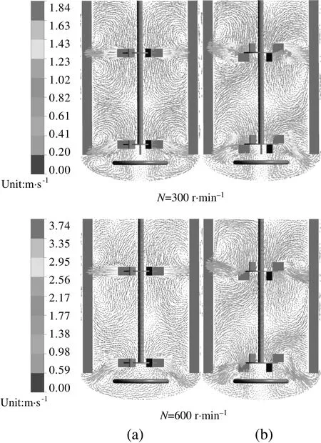
Fig.2.Temporal liquid flow fields generated by(a)SRT and(b)DRT at different impeller rotational speeds.
4.2.Gas hold-up
4.2.1.Gas dispersion patterns
Gas hold-up is a direct indication of the effective gas-liquid interfacial area for mass transfer of the stirred vessel.Experimentally captured gas dispersion images at the operating conditions studied here are firstly displayed below to test the superiority of DRT in dispersing the gas.Fig.3 indicates that the gas is in the fully dispersed regime for both impellers working under the experimental conditions.What in common for both impellers is that,little gas is dispersed near the vessel bottom.A large amount of bubbles are observed in the region adjacent to the impeller,whilst a small number is present in regions between the upper and lower impeller,especially when the impeller rotational speed is low.At larger speed,the situation can be improved.By comparison,although there are no obvious visual differences,a more uniform dispersion state is achieved when DRT is employed.But at the most extreme conditions studied(N=700 r·min-1,Q=0.6 m·h-1),this advantage seems to disappear.

Fig.3.Gas dispersion images of(a)SRT and(b)DRT.
4.2.2.Gas hold-up distribution
Fig.4 shows the gas hold-up distributions obtained from the CFD simulations at t=30 s.Results obtained under two operating conditions(N=600 r·min-1,Q=0.6 m3·h-1and N=300 r·min-1,Q=0.4 m3·h-1)are presented.When the impeller rotational speed is small,the gas mainly dispersed in the impeller discharge flow regions whether SRT or DRT is employed.The situation is much better with the increase of the impeller rotational speed.Note that for both impellers the gas hold-up in region between the two adjacent impellers are not so high compared with other regions in the vessel.This may be due to the fact that the impeller spacing is too large.With this configuration,the upper and lower impellers act independently.According to the study of Pan et al.[34]and Khopkar and Tanguy[35],this belongs to the parallel flow pattern,which has been proved to be adverse for gas dispersion.Studies show that there is pressure difference between each side of the impeller blade.The disc of the Rushton type impeller has an advantage in preventing gas from passing through the lower shear region and forces the gas flow through the high shear impeller tip region[36-38].However,dispersion of the accumulated gas remains to be a problem.This will be solved in our future work by retro fitting the standard Rushton impeller.
In addition,quantitative comparisons of the time-averaged gas holdup under different operating conditions were also performed.Here,eight radial positions,i.e.,20、40、60 and 80 mm from the impeller shaft in the left and right half of the vertical plane passing through the axis were selected.Distributions of the average gas volume fractions in the axial direction are presented in Figs.5 and 6.At all the radial positions,the gas hold-up is generally higher when DRT is used.The average gas volume fractions are listed in Table 2.An average increase about 6%-18%was achieved.This finding further validates the merit of DRT in the mixing of gas-liquid in stirred vessels.

Fig.4.Numerically obtained gas hold-up distribution of(a)SRT and(b)DRT under different operating conditions.

Fig.5.Axial profiles of gas hold-up at different radial positions:(a)20,(b)40,(c)60 and(d)80 mm from the shaft in the left and right half of the vertical plane.Operating condition:N=600 r·min-1,Q=0.6 m·h-1.
4.2.3.Measurement of dissolved oxygen
Experimental set-up is shown in Fig.7.The dissolved oxygen experiments were carried out at 23°C in the same stirred vessel as that employed in the numerical study.At this temperature,the saturated dissolved oxygen in water is 8730 μg·L-1.The activated-sludge effluent was used as the working fluid since it contained aerobic bacteria.Before experiment,no air was aerated and the dissolved oxygen level is zero because the dissolved oxygen was completely consumed by the bacteria.Air was aerated via an OLF-3540 air compressor(Shengyuan Air Compressor Manufacturing Co.,Wenling,Zhejiang,China),and the flow rate was controlled by a LZB-10 rotor flowmeter(Qiquan Flowmeter Co.Ltd,Yuyao,Zhejiang,China).When aeration,the aerobic bacteria began to consume the dissolved oxygen,and after some time there reached a balance between the aerated and consumed oxygen.For different operating conditions,the time needed for reaching the equilibrium was different and generally 20 min were required.Then the dissolved oxygen under the steady state was measured with the In Pro 6050 O2sensor(Mettler Toledo,Switzerland).The dissolved oxygen at two representative points located in the vertical plane containing the baffles was measured.Point 1 located 100 mm below the liquid surface and point 2 was at the middle place between the upper and lower impeller.Both points were positioned at a distance of 30 mm from the stirred vessel wall.For each operating condition,the measurements were repeated four times and the average results were given in Fig.8.
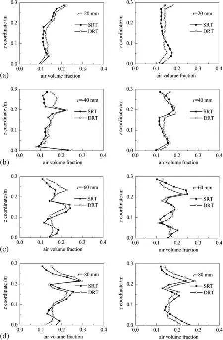
Fig.6.Axial profiles of gas hold-up at different radial positions:(a)20,(b)40,(c)60 and(d)80 mm from the shaft in the left and right half of the vertical plane.Operating condition:N=300 r·min-1,Q=0.4 m·h-1.
From Fig.8 we can see that DRT outperforms SRT under all the conditions studied here.An increase up to 16%was obtained.The most pronounced increases exist at monitoring point 2 and the average increaseis as high as 10.8%.By comparison,an average increase of 4.5%was found at point 1.The reason is that point 1 approaches the liquid surface,and air above the surface was entrained into the liquid by the effect of agitation.This phenomenon is more obvious especially at larger impeller rotational speed and the evidences can be found from Fig.8(a)and(b).In addition,the amount of dissolved oxygen increases with the increase of gas flow rate,and the increase is more evident at lower impeller rotational speed.

Table 2 Average gas volume fraction
Fig.7.Experimental set-up of the dissolved oxygen measurement.
4.3.Power consumption
Power consumption was calculated based on the torque acted on the impeller blades and shaft.The torques consumed by bearing box and mechanical friction were subtracted when computing the net torque.Usually,power consumption can be expressed as the dimensionless power number.The power number before gassing is given as follows:

where P is power consumption determined from the following torque equation:

where M is the net torque before gassing.
For aerated mixing,the power number after gassing was calculated in the same way:

where Mgis the net torque after gassing.
When operated in the gas-liquid mixing,the Rushton type disc impeller developed ventilated cavities behind the blades,which result in the aerated power drop[2,39].The ratio of power consumption after and before gassing is named as relative power demand PRD:

Based on this correlation,smaller value of RPD indicates larger decrease of power number after gassing,which is adverse for the gasliquid mixing efficiency.
Study shows that when Re≥2×10⁵,the power number is constant.It is independent of Re but dependent on the impeller type[40].For the conditions studied here,the minimum Re is 3.18×10⁵and accordingly,the power number is invariable.The power numbers of SRT and DRT configurations(composite impellers)are listed in Table 3.It can be seen that,before gassing,the simulated power number for SRT is 7.31.By comparison,power number prediction of DRT is 6.96,which is about 5%lower than the counterpart of SRT configuration.The measured power numbers of SRT and DRT are 9.02 and 8.57,respectively.Overall,the simulated power numbers of SRT and DRT are under predicted with the experimental data and the difference is within 20%.These differences may be due to the weakness of the k-ε model.After gassing,the numerically determined power numbers for SRT and DRT are 4.83 and 4.73,and the PRDare 0.66 and 0.68.Correspondingly,the experimentally measured PRDfor SRT and DRT are 0.53 and 0.55.This is in correspondence with the conclusion of McFarlane and Nienow[41],who pointed out that SRT experiences a power drop of 50%-65%after gassing.

Fig.8.Comparisons of dissolved oxygen between SRT and DRT:(a)point 1,0.4 m3 · h-1;(b)point 1,0.6 m3·h-1;(c)point 2,0.4 m3·h-1;(d)point 2,0.6 m3·h-1.
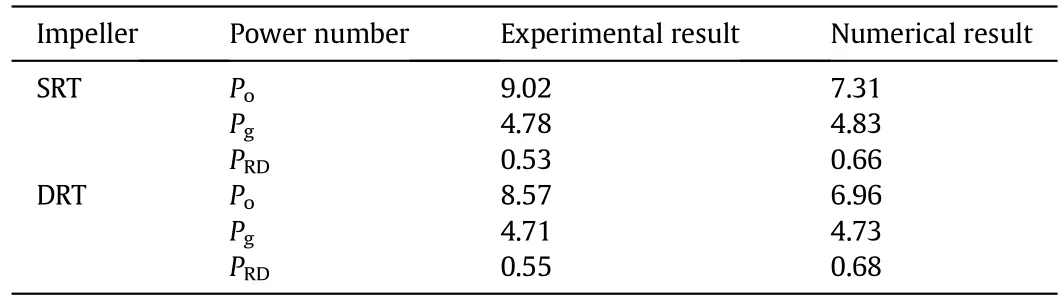
Table 3 Power number of SRT and DRT
5.Conclusions
In this work,DRT was employed in the gas-liquid mixing operation in a baffled stirred vessel.Numerical simulations of the flow field,gas hold-up,dissolved oxygen and power consumption were performed.Results were compared with their counterparts of SRT and good improvements were observed.Generally,the flow field generated by DRT is more chaotic.The flow fields in the top region of the stirred vessel as well as in the region between the upper and lower impellers are promoted.Gas can be dispersed more uniformly and the gas hold-up can be increased up to 18%.The dissolved oxygen performance of DRT also outperforms SRT and the increase is up to 16%.The power consumption of DRT is about 5%lower than SRT.Besides,the power drop after gassing is also a little lower.However,in view of the experimental and numerical errors,the differences await further confirmations.In general,these results indicate promising potential of DRT in the application of gas-liquid mixing in stirred vessels.
Nomenclature
B baffle width,m
C model parameter
CDdrag coefficient
Cssparger off-bottom clearance,m
Cμmodel parameter
C1lower impeller off-bottom clearance,m
C2impeller spacing,m
D impeller diameter,m
d bubble diameter,m
F drag force,Pa
g gravitational force,m·s-2
H liquid level,m
k turbulent kinetic energy,m2·s-2
M torque before gassing,N·m
Mgtorque after gassing,N·m
N impeller rotational speed,s-1
P power,w
Pgpower number after gassing
Popower number before gassing(=P/ρlN3D5)
p pressure,Pa
Q gas flow rate,m3·h-1
Re Reynolds number(=ρlND2/μl)
Reprelative Reynolds number,Eq.(6)
r radial coordinate,m
T vessel diameter,m
t time,s
u velocity vector,m·s-1
z axial coordinate,m
α volume fraction
ε turbulent dissipation rate,m2·s-3
μ dynamic viscosity,Pa·s
μt,lturbulent liquid viscosity,Pa·s
ρ density,kg·m-3
Subscripts
g gas
l liquid
 Chinese Journal of Chemical Engineering2015年11期
- Chinese Journal of Chemical Engineering的其它文章
- N-methyl-2-(2-nitrobenzylidene)hydrazine carbothioamide—A new corrosion inhibitor for mild steel in 1 mol·L-1 hydrochloric acid
- A dual-scale turbulence model for gas-liquid bubbly flows☆
- Convective mass transfer enhancement in a membrane channel by delta winglets and their comparison with rectangular winglets☆
- Cobalt-free gadolinium-doped perovskite Gd x Ba1-x FeO3-δas high-performance materials for oxygen separation☆
- Synthesis and adsorption property of zeolite FAU/LTA from lithium slag with utilization of mother liquid☆
- Simulation and analysis of multi-stage centrifugal fractional extraction process of 4-nitrobenzene glycine enantiomers☆