
Estimating the clutch transmitting torque during HEV mode-switch based on the Kalman filter
2015-04-22 02:33WUXuebin邬学斌ZHANGXin张欣CHENHongwei陈宏伟YANGMeng杨猛
关键词:张欣
WU Xue-bin(邬学斌), ZHANG Xin(张欣), CHEN Hong-wei(陈宏伟), YANG Meng(杨猛)
(School of Mechanical, Electronic and Control Engineering, Beijing Jiaotong University, Beijing 100044, China)
Estimating the clutch transmitting torque during HEV mode-switch based on the Kalman filter
WU Xue-bin(邬学斌), ZHANG Xin(张欣), CHEN Hong-wei(陈宏伟), YANG Meng(杨猛)
(School of Mechanical, Electronic and Control Engineering, Beijing Jiaotong University, Beijing 100044, China)
A power train dynamics model of a coaxial parallel hybrid electric vehicle (HEV) was built for different clutch operating states. With the state vector constituted by the motor rotation speed and the clutch transmitting torque at two successive time steps, a discrete state space model for estimating the clutch transmitting torque was built, and the Kalman filtering algorithm was used to estimate the clutch transmitting torque. The Matlab/Simulink was employed to simulate the clutch transmitting torque for two mode-switch processes. Estimation errors were analyzed through comparing the estimated and simulated values of the clutch torque. Impact of the noise covariance and the sample time on clutch torque estimation errors were explored. The results show that the developed estimation method can be used to estimate the clutch transmitting torque for HEV with good accuracy. The results are useful for torque direct control of automatic diaphragm clutches.
hybrid electric vehicle; mode switch; automatic clutch; Kalman filter; torque estimation
Dynamic coordinated control for drive-mode switch is a key challenge to develop a hybrid electric vehicle (HEV). Hybrid systems using planetary gear sets to couple rotational elements, such as Toyota hybrid system (THS) and GM dual-mode hybrid system, switch their drive-mode by coordinating motor and engine torques[1-2].
In respect of hybrid systems using automatic clutches as drive-mode switch element, the switch control need coordinate torques of motor, engine and clutch. Motor torque and engine torque can be acquired from MCU and ECU respectively, while clutch transmitting torque is unavailable because there is no sensor to measure clutch transmitting torque. Therefore, it is impossible to control clutch transmitting torque directly. The generally followed approaches like the speed control of the driving and driven shaft[3-4]and the travel control of the clutch[5-6]can hardly provide desired clutch transmitting torque for the drive mode switch.
A prerequisite for clutch transmitting torque control is to estimate the clutch friction torque. The engage/disengage travel of automatic diaphragm clutches can be directly controlled. However, the relationship between engage/disengage travel and clutch transmitting torque shows strongly nonlinear characteristics because of the elasticity of clutch elements, the quasi-static variation of friction coefficient, and the wearing of friction lining[7-8]. Therefore, it is difficult to theoretically build an accurate model to calculate the clutch transmitting torque.
State estimation based on analysis of power train dynamics could be a feasible approach to this problem. French scholars R. Amari and P. Tona established a mathematical model for clutch torque estimation by solving Riccati equations, which is a continuous system Kalman-like observer[9]. However, the purpose of their study is to establish the nonlinear function between the clutch travel and clutch torque, and their method can not be used for real-time control.
This paper introduces a method to estimate the clutch transmitting torque for coaxial parallelHEVs. A state space model of the hybrid power train system is built. Based on the model, a Kalman filter is designed to estimate the clutch transmitting torque in the process of drive mode switch. This study makes it possible to control the clutch transmitting torque directly during HEV mode switch.
1 Modeling of a coaxial parallel hybrid power train
The configuration of a coaxial parallel hybrid power train (Fig.1) includes an engine, a motor, a battery set, an automatic clutch, an AMT, and a final drive. The motor is fixed at the input shaft of the AMT. The automatic clutch switchs the drive mode by controlling a dry clutch to engage or disengage. The AMT can automatically change gear ratios by using an actuator.
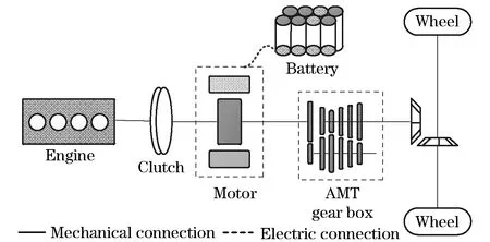
Fig.1 Configuration of a coaxial parallel hybrid power train with AMT
The automatic clutch has three operating states, including disengagement, slipping and engagement. When it is disengaged or slipping, the engine and the motor rotate at different speeds. In that case, the engine torque and the clutch transmitting torque act on the engine crankshaft simultaneously, and the motor torque and the clutch transmitting torque act on the AMT input shaft simultaneously. When the clutch is engaged, it transmits static friction torque, and in that case, the motor torque and the engine torque act on the AMT input shaft simultaneously.
When the clutch is completely engaged, the dynamics equation of the system is
(1)
And when the clutch is disengaged or slipping, the equations are given by
(2)
whereJeis the equivalent inertia of the rotational parts of engine and the input shaft of the clutch,Jmis the inertia of the motor rotor,Jvis the equivalent vehicle inertia measured on the input shaft of the gearbox,Teandweare the engine torque and the engine rotational speed respectively,Tmandwmare the motor torque and the motor rotational speed respectively,Tcis the clutch friction torque,Tris the equivalent running resistance torque measured on the input shaft of the gearbox. In Eqs. (1) (2), the sign depends on the rotation direction of the clutch torque.
The equivalent vehicle inertiaJvis given by
(3)
wheremis the vehicle mass,ris the tire rolling radius,Jwis the wheel inertia,igis the gearbox ratio,i0is the final drive ratio. Without consideration of the wind speed, the vehicle running resistance force is calculated by
(4)
wherefis the tire rolling resistance coefficient and is considered to be a constant,iis the road’s longitudinal gradient,Ais the frontal area, andCdis the drag coefficient. Here, the velocity,v, is measured in m/s, and is linearly correlated towmaccording to
(5)
The equivalent running resistance torque measured on the input shaft of the gearbox is expressed by
(6)
From Eqs.(4)-(6),Trcan be written as
(7)
WithTrbeing replaced according to Eq.(7), Eqs.(1)-(2) can unambiguously describe the power train dynamics behavior.
2 State space model for estimating the clutch transmitting torque
When a vehicle starts, the coaxial parallel hybrid power train (Fig.1) keeps the automatic clutch disengaged so that the motor provides propulsion. When the vehicle speed is up to a threshold value, the automatic clutch gets engaged and the engine starts. In that case, the engine alone, or the engine and the motor jointly supply the motive power. While getting engaged to start the engine, the clutch is sliding and the system has two degrees of freedom. The clutch transmitting torque,Tc, is the engine starting torque and the motor resistance torque at the same time. The dynamics Eq.(2) can be rewritten as
(8)
Eq.(8) models the dynamics characteristics of the engine and motor rotation. The first equation describes the engine dynamics where the engine torque,Te, refers to the transient torque and is hard to acquire. The second equation gives the motor rotor’s dynamics where the motor torque,Tm, is available from the motor controller. And the running resistance torqueTrcan be assumed as a constant since the switching process is short enough. Therefore, the second equation of Eq. (8) can be used to estimateTcand for that purpose, which can be discretized into
(9)
whereTsis the sample time of discretization. Eq.(9) can be rewritten as
(10)
For the time stepk+1, we have
(11)
Eq.(9) can be differentiated and discretized into
(12)
and then transformed to
(13)
For the time stepk+1, we have
(14)
We have identical equation as
(15)
With Eqs.(10)(11)(14)(15) parallel put together, the matrix model of the discrete state system can be expressed as
X(k+1)=A1X(k+1)+A2X(k)+B1U(k+1)
(16)
where the discrete state variable vector X(k) and the control vector U(k) were
(17)
The matrix A1, A2and B1were
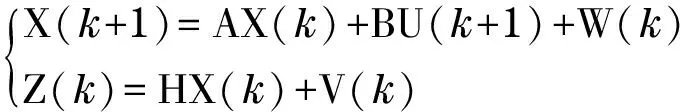
Let A=(I-A1)-1A2, B=(I-A1)-1B1, and take the process noiseW(k) into consideration, Eq.(17) is rewritten as
X(k+1)=AX(k)+BU(k+1)+W(k)
(18)
Z(k)=HX(k)+V(k)
(19)
where H=[1 0 0 0] is the observation matrix, and V(k) is the observation noise.
3 Kalman filtering estimation of the clutch torque
The state equation of Eq.(18) and the observation equation of Eq.(19) constitute the state space model of the linear discrete system.
(20)
The process noise, W(k), and the observation noise, V(k), are assumed zero mean Gaussian white noise with covarianceQandRrespectively. Based on the model, the discrete Kalman filter can be used to estimate the clutch transmitting torque. The Kalman filter is conceptualized as two distinct phases, “predict” and “update”. The predict phase uses the state estimate at the current time step to produce a priori estimate of the state for the next time step. In the update phase, the priori estimate is combined with the observation information at the next time step to refine the state estimate and get a posteriori state estimate[8]. The estimation steps are as follows.
① Predict
The priori estimate of the state for the next time step is given by
(k+1/k)=A(k/k)+BU(k+1)
(21)
The priori estimate covariance is obtained according to
P(k+1/k)=AP(k/k)AT+Q(k)
(22)
② Update
Optimal Kalman gain is given by
K(k+1)=P(k+1/k)HT/[HP(k+1/k)HT+R(k)]
(23)
The posteriori estimate of the state for the next time step is given by
(k+1/k+1)=(k+1/k)+K(k+1)[Z(k+1)-H(k+1/k)]
(24)
The posteriori estimate covariance is calculated by
P(k+1/k+1)=[I-K(k+1)H]P(k+1/k)
(25)
Eqs.(21)-(25) provide iterative steps of the Kalman filter estimating the clutch torque, and some variables are explained as follows.
K(k+1), Kalman gain matrix for the time stepk+1;
P(k+1/k), priori estimate covariance matrix for the time stepk+1;
P(k/k), posteriori estimate covariance matrix for the time stepk;
Q(k), covariance matrix of the process noise;
R(k), covariance matrix of the observation noise.
4 Simulation and analysis on estimating the clutch transmitting torque for HEV drive-mode switch
The HEV drive-mode switch includes two situations. The first situation refers to switching motor drive mode to engine drive mode or to engine-and-motor drive mode, where the automatic clutch is controlled to move from disengagement to engagement. The second one is switching engine drive mode or engine-and-motor driving mode to motor driving mode, where the automatic clutch is controlled to move from engagement to disengagement. This paper focuses on the first situation, simulating and studying the most important mode-switch processes, from motor drive mode to engine-and-motor drive mode.
4.1 Clutch transmitting torque estimation for HEV drive-mode switch
The Matlab/Simulink is employed to simulate the dynamic behavior of the HEV power train. The simulation model is shown in Fig.2.
The varying torques of engine, motor and clutch are determined by the mode-switch controller. The mode-switch control strategy is
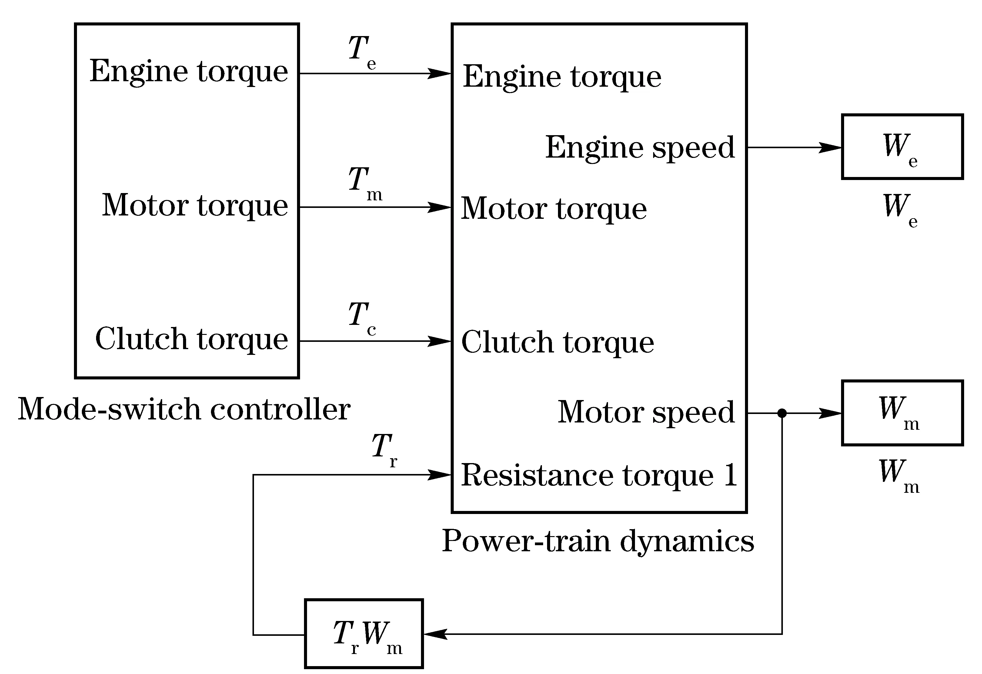
Fig.2 Simulation model of HEV mode-switch process
different under different drive-mode switch situations. Two mode-switch control processes are simulated. Simulation results are shown in Fig.3.

Fig.3 Profile of power train torques for the HEV drive-mode switch
Fig.3a provides torque history for switching from motor drive to engine-and-motor drive. Fig.3b provides torque history for switching from motor drive to engine drive. At the beginning of mode switching in Fig.3a, the motor drive torque is 300 N·m and equivalent resistance torque is 36 N·m. The clutch is completely disengaged and the engine stops, therefore the engine torque and the clutch torque are zero. With the clutch being controlled to get engaged, the engine is driven to start by clutch friction torque. At 0.36 s, the engine generates driving torque and the engine speed exceeds its idle speed. At 0.53 s, the clutch gets into the static friction state, which indicates the end of mode switching. Fig.3b shows the engine starting process, which is part of the whole mode-switch process. The engine torque is always zero since its speed does not reach the idle speed.
The initial motor speed is 1 440 r/min. Based on the above data, for the state space model described by Eq.(20), the initial values of state vector X(0) and control vector U(0) are
(26)
The process noise mainly includes the non-ideal characteristics of the PWM inverter and the motor inner friction torque. The observation noise comes from the quantization errors in programming and the various errors in rotation speed measurement. The noise covariance, Q and R, can be acquired through the experimental analysis. According to Ref. [10], Q and R are assigned by
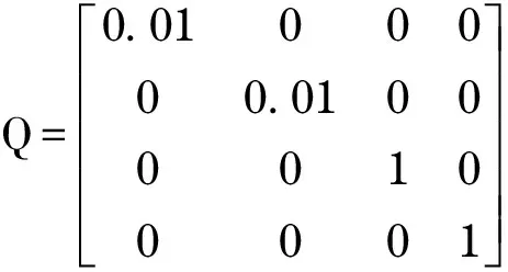
(27)
R=0.01
(28)
With Eqs.(20)-(25) applied to the two switching processes shown in Fig.3, the clutch transmitting torque can be estimated. Fig.4 and Fig.5 compare the estimate torque with the actual one.
Fig.4 and Fig.5 show that the estimated clutch torque has random errors when adding Gaussian white noise signal at the motor torque and speed signal. Fig 4a and Fig 5a compares estimated torque and actual torque, which shows that the estimated torque match with the actual torque very well. Fig.4b and Fig.5b show the error curve of clutch torque estimation. The profile data can be quantitatively analyzed. As for Fig.4, the maximum clutch torque is 104.5 N·m. The maximum estimation error is 3.754 N·m for the period from 0 to 0.3 s. While for the period from 0.3 s to 0.5 s, the error decreases and the maximum is 3.364 N·m with an estimation accuracy of 3.22%. The results indicate that the accuracy of the clutch estimation algorithm is available and effective.
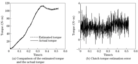
Fig.4 Clutch torque estimation for switching motor drive to engine-and-motor drive
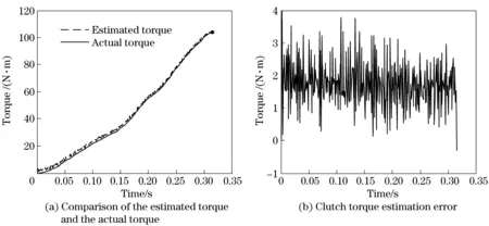
Fig.5 Clutch torque estimation for switching motor drive mode to engine drive mode
4.2 Impact of the noise covariance on the clutch torque estimation
The process noise covariance Q and the observation noise covariance R should be acquired through the experimental analysis. The impact of noise parameters on the clutch torque estimation is examined by simulation and computation. The covariance of process noise is assigned with 0.1×Q, Q and 10×Q respectively for the clutch torque estimation process. Q and R take values according to Eqs.(27) (28), and the sample time is 0.001 s. Fig.6 and Fig.7 show clutch torque estimation errors versus time.
Statistical analysis is performed on the torque estimation error data in Fig.6 and Fig.7, and the mean and variance of the torque errors are filled in Tab.1.
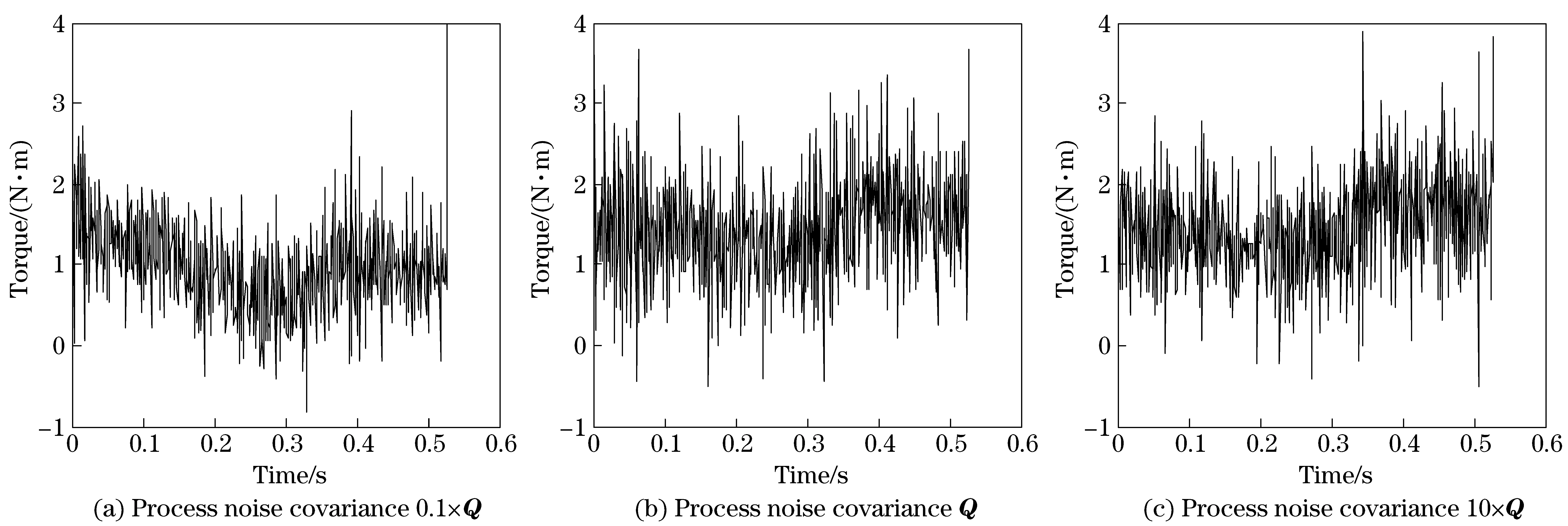
Fig.6 Clutch torque estimation errors for switching motor drive to engine-and-motor drive
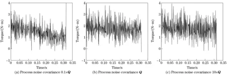
Fig.7 Clutch torque estimation errors for switching motor drive mode to engine drive mode
Tab.1 Statistics of the clutch torque estimation errors at different noise covariance

SwitchcaseMean/(N·m)Variance/(N·m)0 1×QQ10×Q0 1×QQ10×QMotordrivetoengine⁃and⁃motordrive0 971 461 461 411 421 44Motordrivetoenginedrive0 570 620 650 640 690 71
The data in Tab.1 indicates that the mean of torque estimation error gets smaller while the process noise covariance Q becoming smaller. The reason is that the priori estimate covariance, P, is getting smaller along with estimating iteration going. At the beginning, P dominates the values of the Kalman gain since it is largely greater than Q and R. With estimating iteration going, P
becomes smaller, leading to Q and R weighing much more in determining the Kalman gain. If Q is assigned values small enough, the Kalman gain will be near 0, which means the estimation and the observation are decoupled. If Q takes too large values, the estimation will include much more observation noise, leading to more uncertainty.
4.3 Impact of the sample time on the clutch torque estimation
The sample time is an important parameter for the discrete system to ensure the sampled digital signal sufficient for perfect fidelity for the original analog signal. Clutch torque estimation is simulated at different sampling times, while Q and R are set the same value in Section 4.1. Estimation errors at different sampling times are shown in Fig.8 and Fig.9.
According to the torque estimation error data in Fig.8 and Fig.9, the mean and variance of the torque errors are analyzed and filled in Tab.2.

Fig.8 Impact of the sample time on the clutch torque estimation for switching motor drive to engine drive

Fig.9 Impact of the sample time on the clutch torque estimation for switching motor drive mode to the engine-and-motor drive mode
Tab.2 Statistics of the clutch torque estimation errors for different sample times

SwitchcaseMean/(N·m)Variance/(N·m)0 001s0 002s0 005s0 001s0 002s0 005sMotordrivetotheengine⁃and⁃motordrive1 4571 2690 7021 4200 5911 115Motordrivetoenginedrivemode0 6201 1100 4420 6900 7151 117
Fig.8, Fig.9 and Tab.2 show that the mean of clutch torque estimation errors gets smaller with the sample time becoming larger. The mean of the errors for the sample time of 0.001 s is the largest, but estimation errors curve for the sample time of 0.001 s is more stable. It seems that larger sample time is effective. In the development of the actual control system, it is necessary to comprehensively consider the Shannon theorem, and the real-time control and the torque estimation errors for determining sampling time.
5 Conclusions
The two-freedom dynamics model for the power train of coaxial parallel HEVs is built with consideration of the clutch engagement/disengagement states, and on the basis of that, following issues are studied.
① With the motor rotation speed and the clutch transmitting torque at two successive time steps constituting the state variable vector, and with the motor rotation speed as the observation vector, the discrete state space model for estimating the clutch transmitting torque is built. And in order to minimize the influence of noise, the Kalman filtering algorithm is developed to estimate the clutch transmitting torque.
② The Matlab/Simulink is employed to simulate the clutch transmitting torque for mode-switch from motor drive to engine drive and from motor drive to engine-and-motor drive. The estimated and simulated values of the clutch torque are compared, which shows good accuracy of the estimation method.
③ Impact of the noise covariance and the sample time on clutch torque estimation errors are explored, indicating the estimation errors are acceptable if the variations of the noise covariance and the sample time are limited to some range.
It can be concluded that the algorithm developed in this paper provides an estimation method with good accuracy to estimate the clutch transmitting torque for a HEV. On the basis of this algorithm, torque for automatic diaphragm clutches can be controlled to improve the performance of the drive mode switch of a HEV.
[1] Liu J, Peng H, Filipi Z. Modeling and analysis of the Toyota hybrid system[C]∥IEEE/ASME International Conference on Advanced Intelligent Mechatronics, Monterey CA,2005.
[2] Grewe T, Conlon B, Holmes A. Defining the general motors 2-mode hybrid transmission[C]∥Proceedings of the 2007 SAE World Congress, Detroit, MI, 2007.
[3] Glielmo L, Iannelli L, Vacca V, et al. Speed control for automated manual transmission with dry clutch[C]∥43th IEEE Conference on Decision and Control, Atlantis, Paradise Island, Bahamas, 2004.
[4] Dolcini P, Canudas C, Wit de, et al. Improved optimal control of dry clutch engagement[C]∥16th IFAC World Congress, Prague, Czech Republic, 2005.
[5] Zhang Xionghua. Research and development of electro-controlled clutch for HEV[D]. Dalian : Dalian University of Technology, 2005. (in Chinese)
[6] Xie Xianping, Wang Xudong, Zhang Xun. Study on precision position tracking control of electronic controlled automatic clutch[J]. Power Electronics, 2008, 42(10): 58-60. (in Chinese)
[7] Andreas Myklebust, Lars Eriksson. Torque model with fast and slow temperature dynamics of a slipping dry clutch[C]∥2012 IEEE Vehicle Power and Propulsion Conference, Seoul, Korea, 2012.
[8] Vasca F, Innelli L. Torque transmissibility assessment for automotive dry-clutch engagement[J]. IEEE/ASME Transactions on Mechatronics, 2011, 16(3):564-573.
[9] Amari R, Tona P, Alamir M. A phenomenological model for torque transmissibility during dry clutch engagement[C]∥18th IEEE International Conference on Control Applications, Saint Petersburg, Russia, 2009.
[10] Su Weifeng, Liu Congwei, Sun Xudong, et al. Speed controller for induction motors based on Kalman filtering[J]. Jourhal of Tsinghua University (Sci & Tech), 2003,43(9):1202-1205. (in Chinese)
(Edited by Cai Jianying)
10.15918/j.jbit1004-0579.201524.0404
U 463 Document code: A Article ID: 1004- 0579(2015)04- 0449- 09
Received 2015- 03- 10
Supported by the National High Technology Research and Development Program of China (863 Program) (2012AA111104)
E-mail: 09119003@bjtu.edu.cn
猜你喜欢
青年文学家(2022年5期)2022-03-25
Chinese Physics B(2022年3期)2022-03-12
美与时代·城市版(2021年8期)2021-10-01
科学与财富(2021年33期)2021-05-10
Chinese Physics B(2021年1期)2021-01-21
作品(2020年4期)2020-05-11
延河(2020年3期)2020-04-08
Chinese Physics B(2019年2期)2019-02-25
男生女生(金版)(2016年5期)2017-01-17
桂林师范高等专科学校学报(2016年2期)2016-05-24
 Journal of Beijing Institute of Technology2015年4期
- Journal of Beijing Institute of Technology的其它文章
- Influence of shear sensitivities of steel projectiles on their ballistic performances
- Triaxial high-g accelerometer of microelectro mechanical systems
- Dynamic modeling and simulation for the rigid flexible coupling system with a non-tip mass
- Multi-constrained model predictive control for autonomous ground vehicle trajectory tracking
- Optimal tracking control for automatic transmission shift process
- High-precision method of detecting motion straightness based on plane mirror interference