Design and application of refrigerant recovery and filling control system based on MSP430
LI Shi-guang, LI Yao, MENG Xiang-jie, ZHANG Xiao-jing, SUN Hong
(College of Information and Electrical Engineering, Shandong University of Science and Technology, Qingdao 266590, China)
0 Introduction
The refrigerant is a kind of working fluid used for refrigeration to transfer heat and produce frozen effect in air conditioning system, industrial freezer, etc.The staple refrigerants are R134a, R22, etc.The refrigerants of air conditioner, refrigerator and other refrigeration equipment need to be replaced after being used for some time because they are mixed with water and other impurities, or there is leakage, which reduces the efficiency of refrigeration[1].The traditional method of refrigerant emission is to discharge the residual refrigerant into the atmosphere directly, which causes a waste of resources and serious pollution of the environment.
This paper designs a new type of multi functional refrigerant recovery and filling device for air conditioning system based on micro controller unit (MCU) MSP430, according to the different function keys, which can achieve filling, recovery, pressing, vacuumizing, refueling, etc.This device can work based on both set time and set weight, which standardize the recycling and filling of refrigerant.
1 Working principle
1.1 Refrigerant cycle
The refrigerant cycle mainly includes the processes of recovery, filling, pressing, vacuumizing, refueling.
Recovery operation: recovering refrigerant from the air conditioning pipe to refrigerant tank, relying on compression filtration devices within the syst-em[2].
Filling operation: adding a certain amount of refrigerant with the same type to air conditioning system[3].
Pressing operation: pumping the filtered dry air into the air conditioning system with a vacuum pump.If the pressure is constant after a period of time, there is no leakage in the system; otherwise there is a leakage when the pressure drops.
Vacuumizing operation: vacuuming air conditioning system with a vacuum pump, avoiding wet steam and air in the system, which may interfere with filling refrigerant.
Refueling operation: adding oil to the air conditioning system.
1.2 Overall design of system
The designed system includes the following several modules: microprocessor, digital input module, analog input module, digital output module and liquid crystal display (LCD) module.The system structure diagram is shown in Fig.1.
When a key is pressed to set a working state, MCU receives the signals from the weighing sensor by using amplifier and A/D converter to control on-off relay, and then controls the on-off of solenoid valves and compressor, finally completes the refrigerant recovery and filling operation.
During the system working, if the pressure protection switch is closed, the system will break down.Thus, all the data and working status are displayed on LCD screen.

Fig.1 Block diagram of the system structure
2 Design of hardware circuit
2.1 Microprocessor module
Microcontroller MSP430F4793 is used in this design, which is produced by Texas Instrument.This microcontroller has a powerful 16-bit reduced instruction set computing (RISC) CPU, and 16-bit registers to help achieve maximum coding efficiency constant generator[4].
It also has a 3-channel 16-bit sigma-delta analog-to-digital (A/D) converter, and each channel has a pair of differential input and programmable input.
The microprocessor also integrates two 16-bit timers, with 72 I/O pins.An integrated comparison control function of LCD driver can drive up to 160-segment LCD[5].
2.2 Digital input module
Digital input module includes key input and pressure protection input.For the convenience of operation, this design has 12 function keys, connected to MCU port P1.0-P1.7 and P2.0-P2.3, respectively, for external interrupt processing.With these keys, the default parameters and control instructions are sent into the microcontroller for processing.The main function of pressure protection circuit is to monitoring pressure of the system.When the system pressure is higher than a certain value, the pressure protection switch is disconnected from the circuit to ensure that the system pressure does not exceed the safe range, which can protect the personal and equipment safety[6].Pressure protection circuit diagram is shown in Fig.2.

Fig.2 Principle diagram of pressure protection circuit
2.3 Analog input module
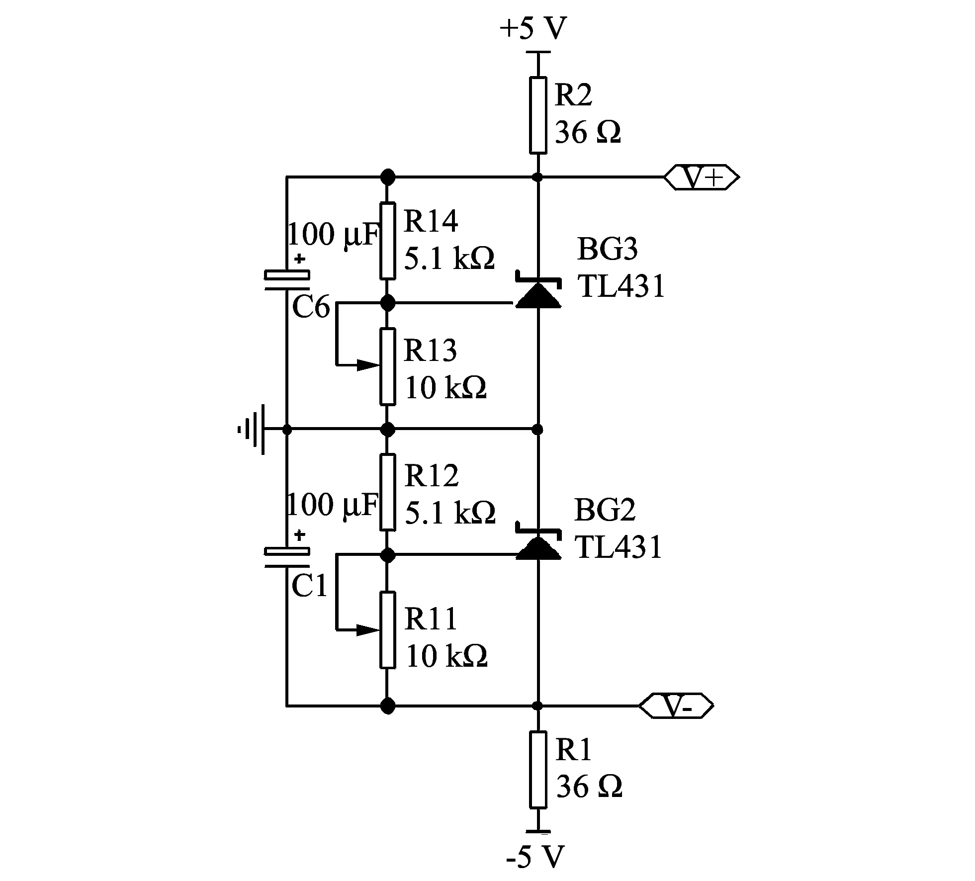
Analog input module uses two TL431 chips to form a constant voltage circuit, which supplies power to the weighing sensor and A/D converter to prevent voltage fluctuation that may cause instability of A/D signal output.TL431 is a three-terminal adjustable shunt voltage reference source with good thermal stability.The typical dynamic impedance is 0.2 Ω, voltage reference error is ±0.4%, and temperature coefficient is 5×10⁻⁸per degree[7].The TL431 internally contains a 2.5 V reference voltage.Therefore, when it is introduced at REF output feedback terminal, the device can be split from the cathode to the anode wide range, controlling the output voltage.Constant voltage circuit diagram is shown in Fig.3.
The output voltage can be calculated by
(1)

(2)
The resistance values ofR2andR1should be chosen to meet Eqs.(3) and (4),
(3)

(4)
The output voltage is adjusted by the variable resistorsR11andR13.
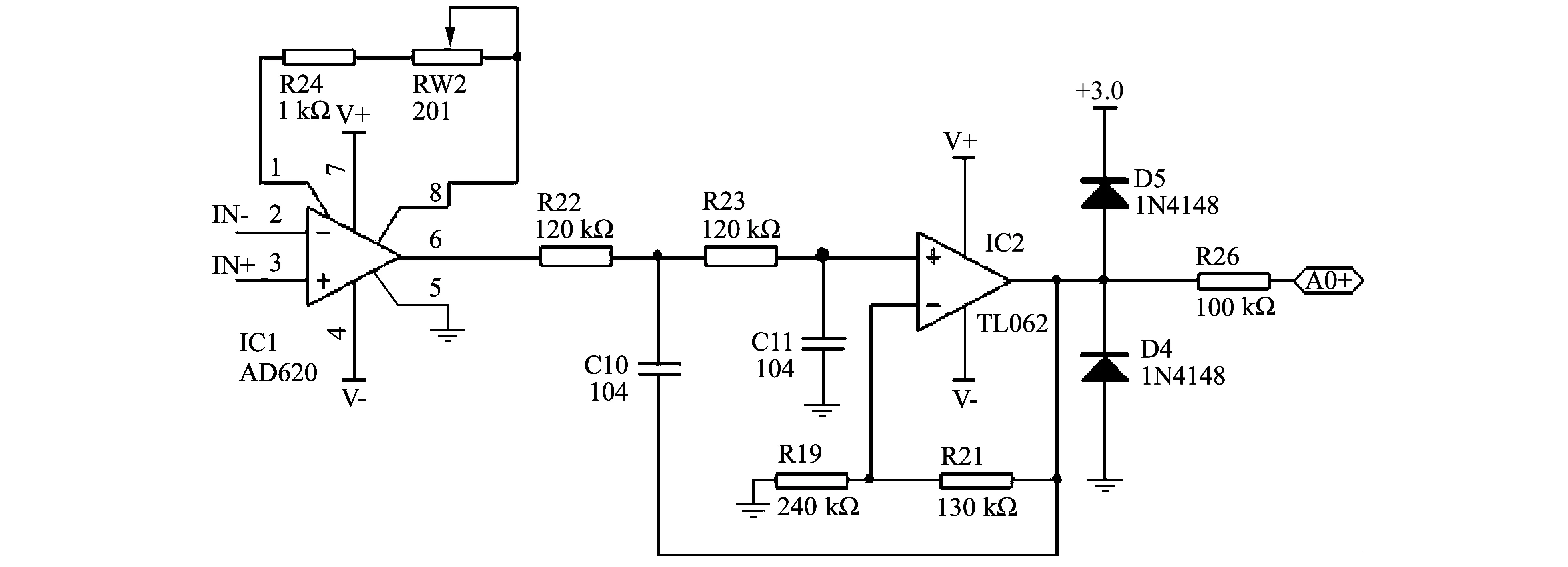
The amplifier circuit uses AD620 and TL062 to amplify millivolt signal of the weighing sensor.Amplifier circuit diagram is shown in Fig.4.

Fig.3 Principle diagram of constant voltage circuit

Fig.4 Principle diagram of amplifier circuit
in Fig.4, AD620 is an instrumentation amplifier with low cost, low noise, high precision, low offset voltage and other characteristics[8].It is easy to be used, which only needs to connect a resistorRGto set the device gain between pin 1 and pin 8 as described in Eq.(5).The gain is adjusted by the variable resistor RW2.
(5)
TL062 is a universal junction field effect transistor (JFET) dual operational amplifier.It has low input offset voltage, low offset current, high input impedance and internal output equipped with short circuit protection.In this design, the second-order voltage-controlled low-pass filter circuit is composed of TL062, and its attenuation ramp rate of amplitude-frequency characteristics is up to -40 dB/dec[9].The passband voltage gain is calculated by
(6)
The cut-off angular frequency can be calculated by
(7)
The cut-off frequency is got as
(8)
The signals greater than 13 Hz are filtered out to ensure data stability.There are two diodes and a resistor connected between TL062 and microcontroller pin.The role of 1N4148, a kind of high frequency switching diode, will limit the amplitude of voltage amplifier output with in -0.7 V-3.7 V and prevent the damage to the microcontroller.R26 is the current limiting resistor.
2.4 Digital output module
The digital output module is mainly used to control the relay, so as to control the solenoid valves and compressor.In order to lock MCU control signal and effectively prevent the maloperation of the relay, this design uses 74LS377 latch.
2.5 LCD display module
Display module with LCD has advantages of simple principle, convenient use, small volume, high modularity and low power consumption.
3 Software design
3.1 Flash reading and writing
When the system runs for the first time, initial parameters need to be set for the refrigerant recycling machine, such as pressure release time, running time, filling weight, recovery weight and weighing sensor range, etc.The data is stored in Flash memory of MCU after being successfully set.The microcontroller MSP430F4793 Flash memory is divided into the main memory and information memory.To keep running parameters in information memory, information memory has four 64-byte segments.In order to prevent the accident which leads to power down while reading abnormal data changes in Flash memory, the method of simultaneous reading and writing multiple Flash segments in this passage is used to read and write data more accurately and reliably.After power is on, the data is read from Flash memory in segments B, C and D.If the data in any two segments is the same, the assignment is used.If the three segments of the data are different, LCD interface prompts the need to reset data.
3.2 Weight measurement
3.2.1 Filtering algorithm
After receiving the analog signal from the weighing sensor, MCU carries out the A/D conversion.In order to guarantee the accuracy of measuring the weight, this paper designs an anti-jamming algorithm based on median average filtering method[10], which can effectively eliminate the pulse interference caused by the deviation of sampling values, and greatly improve the stability and reliability of the measurement.
This algorithm process reads weighing sensor analog signal once every 50 ms, and then A/D conversion is carried out.The sampled data are arranged from the largest to the smallest by MCU, then the average value of all the data is obtained after the largest and the smalled value are removed.
3.2.2 Refrigerant weight
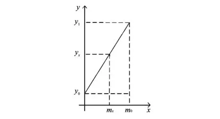
In the processes of filling and recycling, it is necessary to measure the weight of the filling and recovesed refrigerant.The refrigerant weight measuring principle diagram is shown in Fig.5.

Fig.5 Refrigerant weight measuring principle diagram
The abscissaxrepresents the weight value and the ordinateyrepresents A/D conversion value.Weight calibration is needed before the first use of the device, that is, when weighing sensor pallet weight is 0, withY0A/D conversion value isY0; when weighing sensor pallet weight ism0, A/D conversion value isY1.Finally,Y0,Y1andm0are stored in the microcontroller Flash.Thereby a straight line is drawn as shown in Fig.5, where the slope is
(9)
When the refrigerant tank is installed on the pallet of weighting sensor, it can measure the quality of tank and refrigerant.After filling and recycling, the quality of refrigerant tank changes, which can measure the weight of the refrigerant filling or recycling.
4 Conclusion
According to the actual need of recycling and filling refrigerant in air conditioning system, this paper designs a multifunctional refrigerant recycling and filling device.The device can be used for refrige-rant recycling, purifying and quantitative filling.At the same time the device has a leak point pressure test and can use atmospheric pressure to add refri-gerant oil after vacuumarizing.In the process of design, the hardware part adopts MSP430 single-chip microcomputer control system, high-precision weighing sensor and a high performance amplifier; software programming uses the median average filtering algorithm.Practice has proved that the control system can realize automatic control and working process without manual intervention.At the same time, the device has the advantages of low cost, good stability, high reliability, highly economic and environmental value.
[1] NIU Gang, ZHANG Yue.How to protect air conditioning system in abnormal refrigerant quantity.Private Science and Technology, 2010, 15(9): 31.
[2] LIU Jun, TANG Zhi, GUO Ming-xin, et al.Refrigerant recycling equipment.Chinese Patent, No.2742351, 2005.
[3] LU Yi-hang.Principles and composition of automotive air condition refrigerant filling equipment.Industrial Control Computer, 2010, 23(8): 85-86.
[4] KANG En-tao.Design of wireless transceiver system in measuring bolt stress based on MSP430.Master thesis.Shandong University of Science and Technology, 2011.
[5] JIAO Bing, YE Song, WEN Ya-ting.Low-power consumption principle of MSP430 and its application in sea temperature measurement.Modern Electronics Technique, 2011, 34(10): 189-192.
[6] LAN Ruo-ming.PID flow controller with pressure protection.Modern Electronics Technique, 2010, 17: 187-188.
[7] LEI Kai-zhuo, HOU Jian-ping, HUANG Jian-guo.Study on the principle and application of TL431.Power Technology Application, 2001, 4: 34-36.
[8] HE Zhong-jiao.Heart rate detection based on AD620.Science Information, 2007, 5(2): 49, 61.
[9] MENG De-jun, LIN Zhi-gui, ZHONG Qing-qing.The design and implementation of temperature acquisition system based on AW60.Journal of Suzhou University, 2010, 30(2): 6-11.
[10] ZHAO YI, MOU Tong-sheng, SHEN Xiao-li.Algorithms of digital filter in the microchip system.Electron Measurement and Instrument, 2001, 38(6): 5-8.
 Journal of Measurement Science and Instrumentation2014年1期
- Journal of Measurement Science and Instrumentation的其它文章
- Error separation in CMM coordinate metrology
- Design and theoretical analysis of test system for propellants’ gas pressure in warhead
- A new probe for atmospheric electric field mill
- Experimental analysis of high temperature capacitance variance of MLCC
- Application of RLS adaptive filtering in signal de-noising
- QIM digital watermarking based on LDPC code and message passing under scaling attacks
