A new probe for atmospheric electric field mill
SUN Jian, WANG Jian-ling
(College of Information and Electrical Engineering, Shandong University of Science and Technology, Qingdao 266590, China)
At present, the applications of ground atmospheric electric field mill are wider and wider.It is used not only for weather forecast by Meteorological Agency, but also for lightning protection and other fields.Generally, atmospheric electric field mill is comprised of sensor probe and follow-up data processing host.The former is the main difficulty in design.In this paper, a novel and practical probe for atmospheric electric field mill is designed to collect related data at home and abroad.
1 Structure and principle of probe
The probe mainly consists of data acquisition circuit for atmospheric electric field, preamplifier circuit and phase sensitive detection circuit.The data acquisition circuit is made up of two stators and one rotor.It can suppress interference better and get more ideal test signals.Preamplifier circuit is made of current-to-voltage (I-V) conversion circuit, differential amplifier circuit and secondary amplifying circuit.
The concrete structure of probe is shown in Fig.1.It consists of a rotor, two stators, small motor, ground carbon brush, preamplifier circuit and phase sensitive detection circuit.In order to ensure good performance of the equipment, the following measures are taken.A double weak polarization composite material between stator and insulation pillar of grounding shell is used.It can not only guarantee precise distance between stator and ground potential, but also prevent short circuit due to rainy day and tide night.Mechanical coupling between principal axis and motor shaft is used to achieve good electrical isolation between the motor and probe, which prevents the motor rotation noise from having an impact on the signal.What is more, the special ground carbon brush, long-life brushless motor and the structure of probe without external screw assembly are adopted.The above measures can ensure the probe working in various environments for a long time[1].
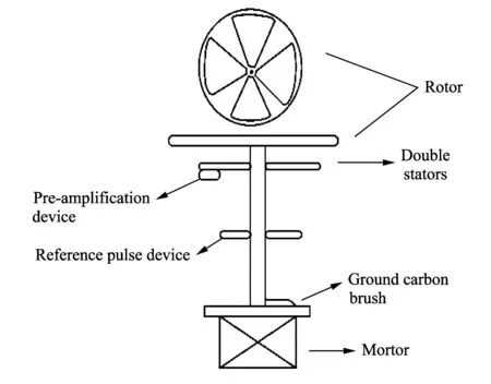
Fig.1 Structure diagram of probe for atmospheric electric field mill
For this double-stator probe, rotor is alternately exposed to or blocked in the atmospheric electric field along with the rotating motor.Therefore, two kinds of current signals with the same size and opposite phase are produced on double stators by continuous cutting off atmospheric electric field.After these signals are entered into the input terminal of preamplifier circuit, the following steps are taken.Firstly, two voltage signals are obtain when those signals go through I-V conversion circuit individually.Secondly, those voltage signals get into differential amplification circuit.Because the two stators are independent of each other and have the same interference, the interference will be offset by differential input circuit.Finally, those weak signals enter into secondary amplifying circuit and an ideal signal is got.
2 Signal acquisition circuit for atmospheric electric field
Because conductor can produce charge in atmospheric electric field, the ways of signal acquisition in atmospheric electric field include field mill type and double ball type[2].We select field mill type because of its accurate detection and effect well.Generally, the field mill type mostly uses one stator and one rotor.This structure has little capability of anti-interference[3].The interference include fluctuation noise caused by motor rotation, edge effect noise caused by rotor rotation, the accumulated charge in the air and free ion flow in the space.The interference even covers up the signal to be measured and makes it produce big distortion in output terminal, which has a serious impact on the accuracy of measurement results[4].
For these reasons, double stators are used for signal acquisition in atmospheric electric field, just as shown in Fig.1.The rotor’s metal blade must be connected with the ground.The principle of double-stator electric field mill is as follows.Two stators are alternately sheltered by rotary rotor, and the rotor and stator are equal to the plate capacitor.When the atmospheric electric field is strong enough, it will induce potential difference between two metal plates.The electric potential difference is proportional to the strength of atmospheric electric field.Therefore, the atmospheric electric field strength can be concluded by the current value on the stator[5].
The charge produced in the field mill type’s single stator can be calculated by
Q(t)=-εEA(t),
(1)
whereQ(t) is produced charge;εis permittivity, and it approximates to vacuum permittivity:ε=8.85×10⁻¹²;Eis atmospheric electric field strength under test;A(t) is the area of stator which is exposed to the electric field.Because the speed of rotor is fixed,A(t) periodically changes with time depending on the periodic triangle wave.
3 Preamplifier circuit
Static atmospheric electric field is a direct current component.The induction in the stator can produce direct current and it is very small with the order of magnitude of 10-11-10-12V[6].There will be a big distortion when the direct signal is amplified by such a magnitude, so I-V conversion circuit must be used to transform weak direct signal to alternating voltage.Then, those alternating voltage signals go through the main amplifier circuit, which is composed of differential amplifier circuit and secondary amplifying circuit.The instrumentation amplifier is selected in the secondary amplifying circuit because the signal is relatively weak and interference is big[7].Finally, an ideal signal is got when signal processing is completed.The process is shown in Fig.2.

Fig.2 Block diagram of preamplifier circuit
3.1 I-V conversion circuit
I-V conversion circuit is shown in Fig.3.
Because the acquired signal from the stator is very weak, amplifier AD795 is needed for precise I-V conversion owing to its characteristics of low noise, low zero drift and high input impedance.The conversion principle is described in the following.
I-V conversion circuit converts electric charge into voltage[8].In order to prevent the amplifier from being saturated, which can cause capacitances C1 and C2 to charge for too long time, resistances R1 and R2 are connected in parallel with C1 and C2, respectively.
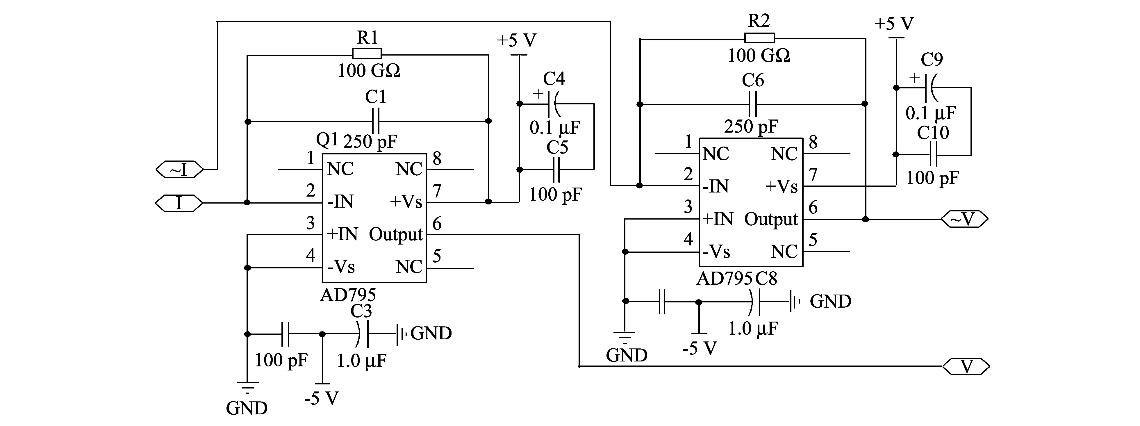
Fig.3 I-V conversion circuit
The alternate inductive voltage signalV(t) is obtained when the induction current signal produced in the stator goes through I-V conversion circuit.The expression in the period ofTis[9]
(2)
whereIis induction current signal produced in the stator;Ris feedback resistance in I-V conversion circuit;Cis feedback capacitance in I-V conversion circuit;Tis period of rotor;VRCis equivalent amplitude of induction voltage signal whent=T/2;Kis constant that can be calculated by
(3)
3.2 Differential amplifier circuit
Fig.4 is differential amplifier circuit.Owing to the structure of two stators, two signals are got after I-V conversion, each of which is composed of induction signal with interference signal.The two induction signals are differential mode voltage signals with the opposite phase, the same size and frequency.But two interference signals are common mode signals which are all equal in size, frequency and phase.The differential amplifier circuit can amplify differential mode signal and restrain common mode signal effectively.Thus, double sensitivity can be obtained theoretically.
OP07 is selected as the main operational amplifier in differential amplifier circuit.The OP07 is bipolar integrated amplifier with low noise and stabilized zero point and without chopper.It has very low input offset voltage, and the max is 25 μV, so OP07 does not need extra zeroing circuit.At the same time, it has the characteristics of low input bias current and high open-loop gain.
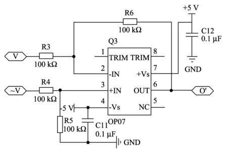
Fig.4 Differential amplifier circuit
3.3 Secondary amplifying circuit
The secondary amplifying circuit is shown in Fig.5.The main function of this circuit is to amplify less interference but weak signal.Instrumentation amplifier AD620 is used in this paper.It has very low noise and offset voltage.The gain of AD620 circuit is decided by one extra resistorRG.The formula of gain isG=(R1+R2)/RG+1, whereR1andR2are the internal resistors,RGis extra resistor.If the value ofRGis 1 kΩ, the gain of this circuit is almost 50.
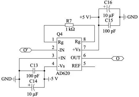
Fig.5 Secondary amplifying circuit
4 Phase sensitive detection circuit
Because atmospheric electric field is described in the form of vector, not only the strength but also the polarity need to be detected[10].
The small sheetmetal in reference pulse device passes through optoelectronic switch at a frequency ofωwhen the rotor is rotating.The light accessing to light emitting diode is cut off or has passed periodically, which makes phototriode be in the state of cut-off or breadover.Reference pulse can be expressed by[11]
(4)
The phase sensitive detection circuit is shown in Fig.6.
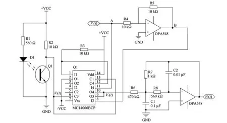
Fig.6 Phase sensitive detection circuit
In Fig.6, two chips of OPA548 are used for A1 and A2.MC14066BCP consists of four independent switches capable of controlling either digital or analog signals.Synchronous pulse signal generating circuit is composed of photoelectric switches and resistors R1 and R2, where TP880 is selected as photoelectric switch.Full wave detection circuit includes MC14066BCP, amplifier A1 and resistors R3, R4 and R5.Amplifier A2, capacitors C1 and C2, resistors R6, R7, R8 and R9 make up second-order active low-pass gilter.It can filter out extra harmonic.
Cut-off frequency of second-order active low-pass filter is
(5)
The working principle of this circuit is analyzed when atmospheric electric fieldEis positive value.It has been known thatV(t) is not completely triangle wave, as shown in Fig.7.The left is positive waveform ofV(t) in atmospheric electric field.The right is negative one.
Taking Fig.7(a) as an example, the waveform ofV(t) is analyzed.In Fig.6, the voltage of point A is negative half-cycle, but point B’s voltage is positive half-cycle.Analog switches 1 and 3 are off, but switch 4 is on, so pin O4’s output is negative half-cycle and pin O3’s output is high impedance.Those are in the situation state thatV(t) is negative half-cycle andVc(t) is low.At the same time, the same results can be got whenV(t) is positive half-cycle andVc(t) is high.V2(t) is the voltage of point A with positive half-cycle and the voltage of point B is negative half-cycle.Analog switches 1 and 3 are on but switch 4 is off.So pin O4’s output is high impedance and pin.O3’s output is negative half-cycle.V2(t) is always in negative half-cycle in the whole cycle.Positive direct voltageVo(t) is obtained when this signal passes through reverse low-pass filter.Therefore, it can be known that the measured electric field is positive.The analysis process is reverse when the measured electric field is negative, as shown in Fig.7(b).
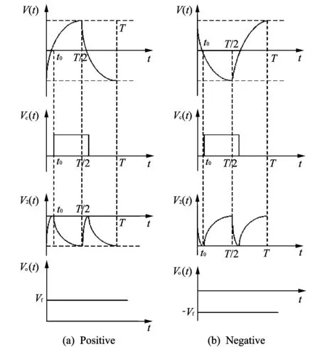
Fig.7 Waveform of V(t)
5 Simulation with Multisim
The circuit is tested by simulation software Multisim.Two current sources simulate two signals produced in the stator.Because the two actual signals are weak with the same frequency and opposite phase, the amplitudes of the two simulation current sources are set at 10 nA, the frequencies is 60 Hz and the phase difference is 180°.Alternating voltage can be got after the signals go through the I-V conversion circuit.The peak value is about 1 mV, as shown in Fig.8.After those signals pass through differential amplifier circuit and secondary amplifying circuit, two signals from channel A and channel B are obtained, as shown in Fig.9.The channel A is the signal after differential amplifier circuit with peak value of about 2 mA.The channel B is the signal after secondary amplifying circuit with peak value of approximate 100 mA.The gain is 50 corresponding to the settings.At the same time, the result is in accord with the anticipation.
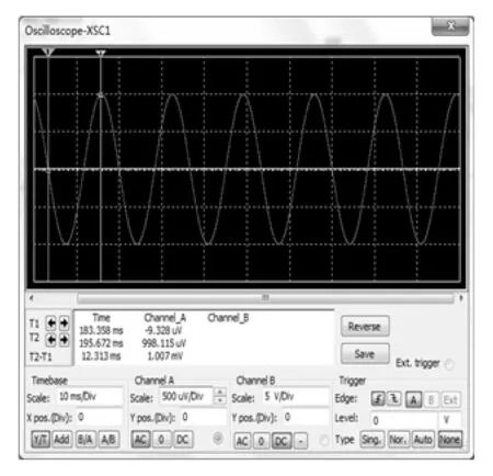
Fig.8 Signals after I-V conversion circuit
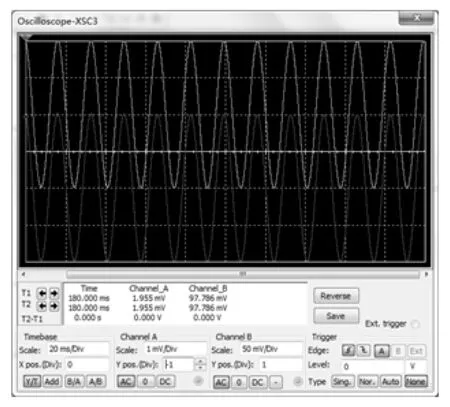
Fig.9 Signals after differential amplifier circuit and secondary amplifying circuit
6 Conclusion
This paper designs a new and practical probe for atmospheric electric field mill.It can transform the weak signal produced in the stator into an ideal alternating voltage signal.At the same time, the phase sensitive detection circuit can detect the polarity of the atmospheric electric field.This double-stator probe also has more precision.Its feasibility can be proved by the simulation results using Multisim.
[1] LUO Fu-shan, ZHUANG Hong-chun, HE Yu-hui, et al.Rotary atmospheric electric field mill of KDY type.Electrical Measurement & Instrumentation, 1993, 30(4): 17-21.
[2] Rakov V A,Uman M A,Fernandez M I.Direct lightning strikes to the lightning protective system of a residential building: triggered-lightning experiments.IEEE Transactions on Power Delivery, 2002, 17(2): 575-586.
[3] XING Hong-yan, JI Xin-yuan, TANG Hai.Research and design of differential atmospheric electric field mill.Chinese Journal of Scientific Instrument, 2008, (8): 305-308.
[4] LI Di-fei, BI Wu, ZHANG Ming-yuan, et al.Design of differential atmospheric electric field sensors.Forestry Machinery & Woodworking Equipment, 2009, 37(10): 35-51.
[5] LUO Fu-shan, HE Yu-hui, ZHANG Hua-wei.Calibration method of electric field.Chinese Journal of Space Science, 2007, 27(3): 223-226
[6] SUN An-ping, YAN Mu-hong, ZHANG Yi-jun, et al.A numerical study of space charge formation beneath thunderstorm.Chinese Journal of Atmospheric Sciences, 2001, (1): 16-24.
[7] ZHANG Shui-rui, ZHENG Wen-gang, HUANG Dan-feng, et al.The design of preamplifier circuit based on weak signal detection.Microcomputer Information, 2009, (2): 223-224.
[8] LI Yan, WANG Zhen-hui.Using wavelet analysis to process the data of ground atmospheric electric field.Journal of the Meteorological Sciences, 2012, 32(2): 177-181.
[9] LUO Fu-shan, HE Yu-hui, ZHANG Jian.The new inverted electric field mill.Chinese Journal of Space Scienec, 2004, (6): 155-157.
[10] Montanya J, Bergas J, Hermoso B.Electric field measurements at ground level as a basis for lightning hazard warning.Journal of Electristatics, 2004, (60): 241- 246.
[11] TANG Hai, XING Hong-yan, JI Xin-yuan.Analysis and design of phase sensitive detector in atmospheric electric field mill.Moedern Electronics Technique, 2009, (13): 8-10.
 Journal of Measurement Science and Instrumentation2014年1期
- Journal of Measurement Science and Instrumentation的其它文章
- Error separation in CMM coordinate metrology
- Design and theoretical analysis of test system for propellants’ gas pressure in warhead
- Experimental analysis of high temperature capacitance variance of MLCC
- Application of RLS adaptive filtering in signal de-noising
- QIM digital watermarking based on LDPC code and message passing under scaling attacks
- Energy-aware cooperative spectrum sensing for underground cognitive sensor networks
