Design and theoretical analysis of test system for propellants’ gas pressure in warhead
BIAN Jing-jing, WU Zhen
(Science and Technology on Electronic Test & Measurement Laboratory, North University of China, Taiyuan 030051, China)
There are diverse ways of dispersing cluster bombs such as propellant gas pushing dispersion and center tube explosion dispersion.Especially, opening the hatch is a complicated dynamic process[1].For centre tube explosion dispersion, the internal gas pressure will affect the reliability of warheads.It has a strong influence on accurate opening of the warhead as well as bullet distribution, thus damage effect of the warhead is affected indirectly[2].A high-pressure environment will produce from gas pressure generated by the warhead inside, so it is necessary for test system to be placed right position in advance and to endure high-pressure impact after explosion.Aiming at the above-mentioned problems, such as long test preparation and poor explosion field, a gas-pressure storage test system for cluster bombs is proposed, which uses the way of breaking line for power up.The device has such advantages as easy to use, small size, strong shock resistance, no lead, installed on the side of the bomb in direct contact with bomb lumen and moving with bomb skin after explosion, no loss of data, high precision and reusability.In a word, it is an ideal gas pressure test system for cluster bombs[3].
1 Hardware design
1.1 Structure of test system
The test system consists of a high-strength shell, some sensors and a circuit module.The circuit module includes analog adapter circuit, interface circuit, and system control circuit composed by central controller and power controller.The system must be fixed outside the bomb skin and moves together with it.Thus, The test system should be of small size, low power consumption and high overload resistance to ensure correct trajectory of bomb skin after opening the hatch as well as the reliability of the system.Accordingly, the volume of control chip must meet the above requirements.MSP430 of TI Company has rich peripheral modules, so it is chosen as the controller.
1.2 Operating principle of test system
Data acquisition and storage are completed under the control of central controller.After conversion from charge to voltage by analog adapter circuit, filtered and amplified by amplifier of microcontroller unit (MCU), the signals are acquired and stored by internal A/D converter after conditioning.The system adopts the ways of inner trigger and negative delay storage.The data is stored in random access memory (RAM) and Flash before and after triggered to ensure complete data before triggered and no loss of data in case of power-failure in recovery.The test system will be in a low power state when sampling is finished.The aquired data can be read from serial ports and shown.The block diagram of test system is shown in Fig.1.
The design of state diagram is a process that depends on the movement of the object to determine the state structure of the test system.State transition diagram is shown in Fig.2.
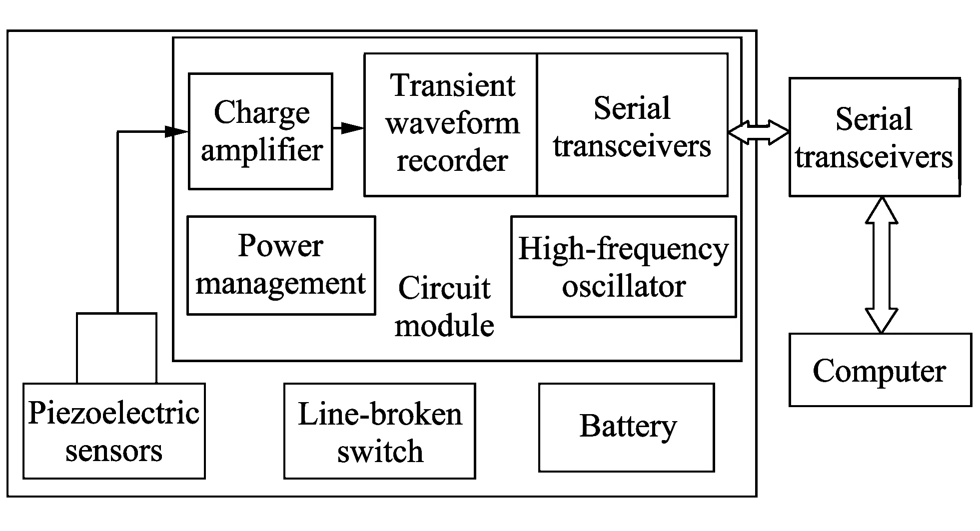
Fig.1 Block diagram of propellants gas pressure test system
When the system is powered up, MCU will wait until programming signal goes into either the low power state or reading the last data state.Once the programming signal appears, MCU will be in a low power state and waiting for line-broken signal.Now, the current power consumption of the whole system is about 50 μA.When line-broken signal arrives, the system is powered up and each of the modules such as clock circuit, A/D converter, D/A converter, Flash and direct memory access (DMA) are initialized to start working.Now, the system is in a cyclic sampling stage.First of all, digital signals obtained by conversion are stored in RAM before triggered.When trigger signals equal the initial settings, MCU will respond to the interrupt signal and change memory space.Furthermore, all of the digital signals converted by A/D converter will be written into internal Flash.At the same time, previous data in RAM is also shifted into Flash.Finally, the system stops sampling and comes back to low power consumption state to wait for reading data.After serial initialization is completed, transceivers and reading ports can get data.The system is in low power consumption state again after reading data and to be waiting for the next reading signal.
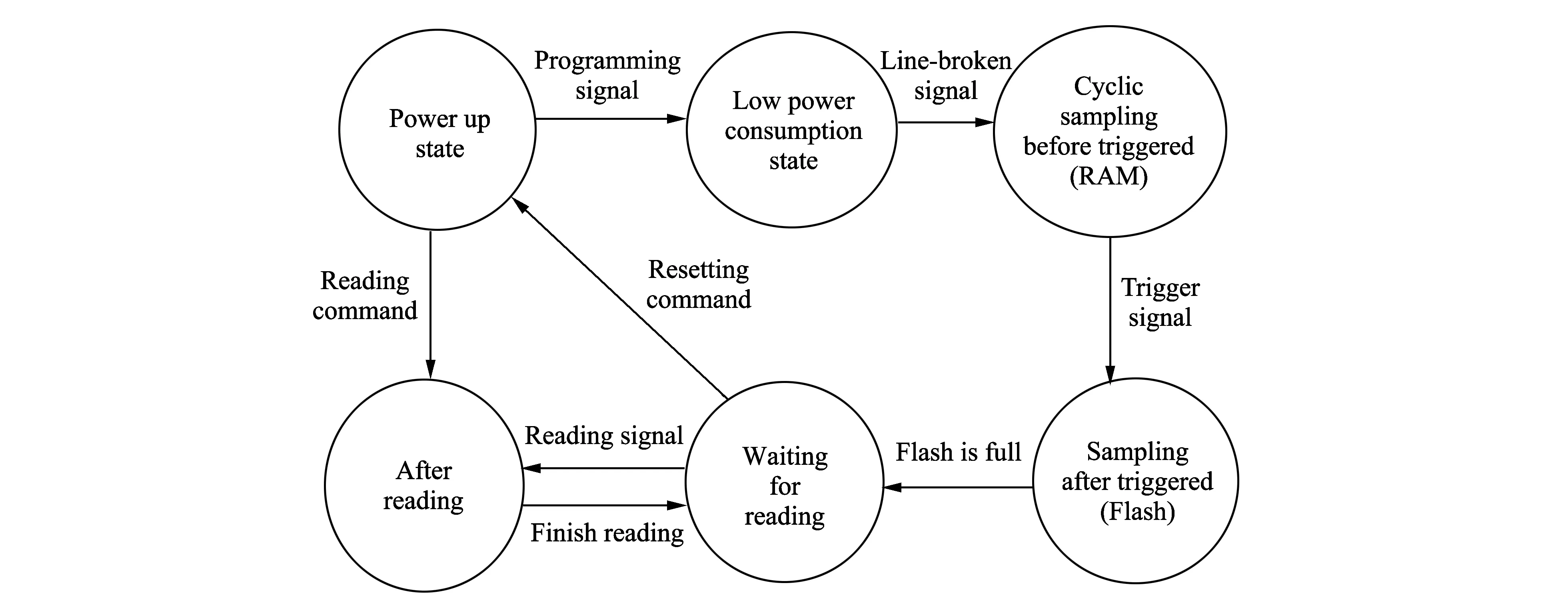
Fig.2 State transition diagram of propellant gas pressure test system
1.3 Key technologies of test system
The tset system uses battery for power supply.Battery capacity is limited and working environment of the system is bad, but it is impossible to replace it during the system working.In order to meet the test requirement, a well designed scheme for low power consumption is presented based on the method of breaking line for power up.
The detailed design for low power consumption is as follow:
1) Choosing a widely accepted 16-bit ultra-low power mixed signal processor as the main controller.
2) The system works at alternate high/low speed via crystal oscillator.
3) Shortening the chip selection time of high-power chip as much as possible.
4) Power management system is designed to supply fixed voltage for MCU.In this way, not only MCU operates normally, but also power consumption is reduced.The current is about 5 mA in full power state[4].The system modules and power consumption are shown in Table 1.
Because the test system needs to be fixed outside or inside of the bomb skin and makes preparations for the test, it is necessary for the test system to be in low power consumption state during the test.For this reason, the system adopts the method of breaking line for power up, in which a high-temperature outlet line from the system is broken for power up to make the system be in cyclic sampling state before triggered.The circuit schematic diagram is shown in Fig.3.
When line-broken node is connected, the node voltage at Vonis
When line-broken node is disconnected, the node voltage at Vonis
where 9 700 k is resistance value of P2 port to GND.Trigger D ensures 1Q output high level signal after breaking the line and makes P2 port keep receiving high level signal after receiving line-broken signal no matter whether it will be connected or not, avoiding accidents caused by power up again[5].
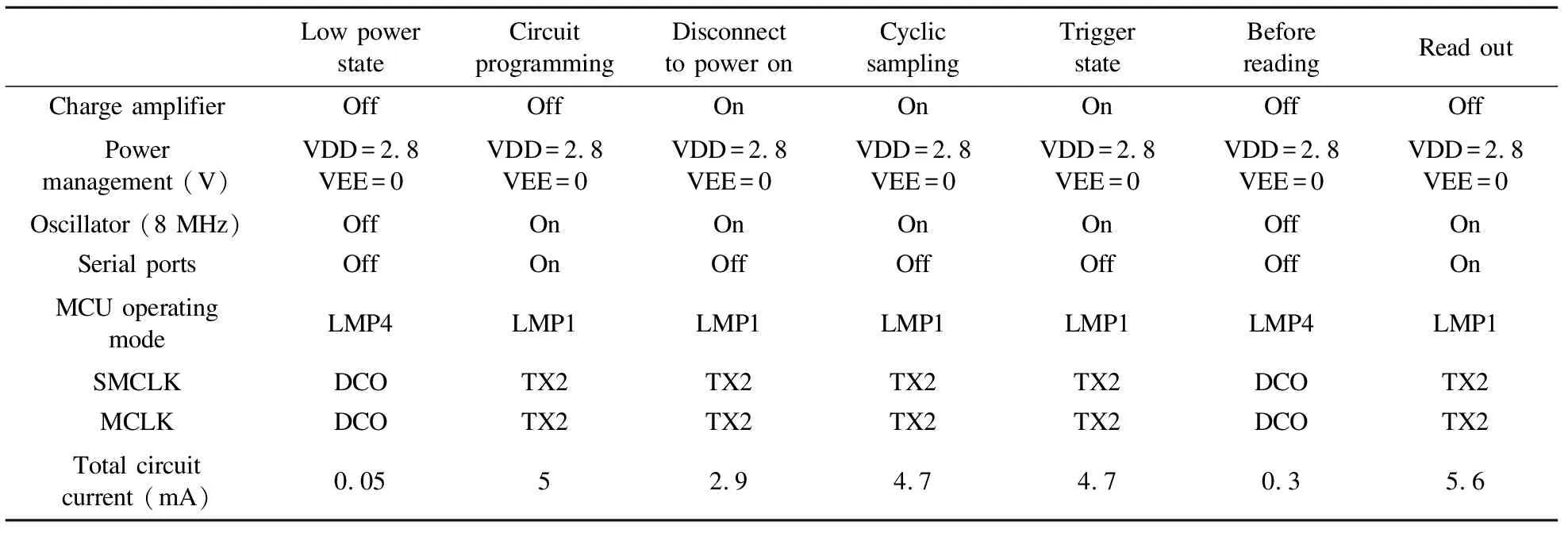
Table 1 System modules' states and power consumption
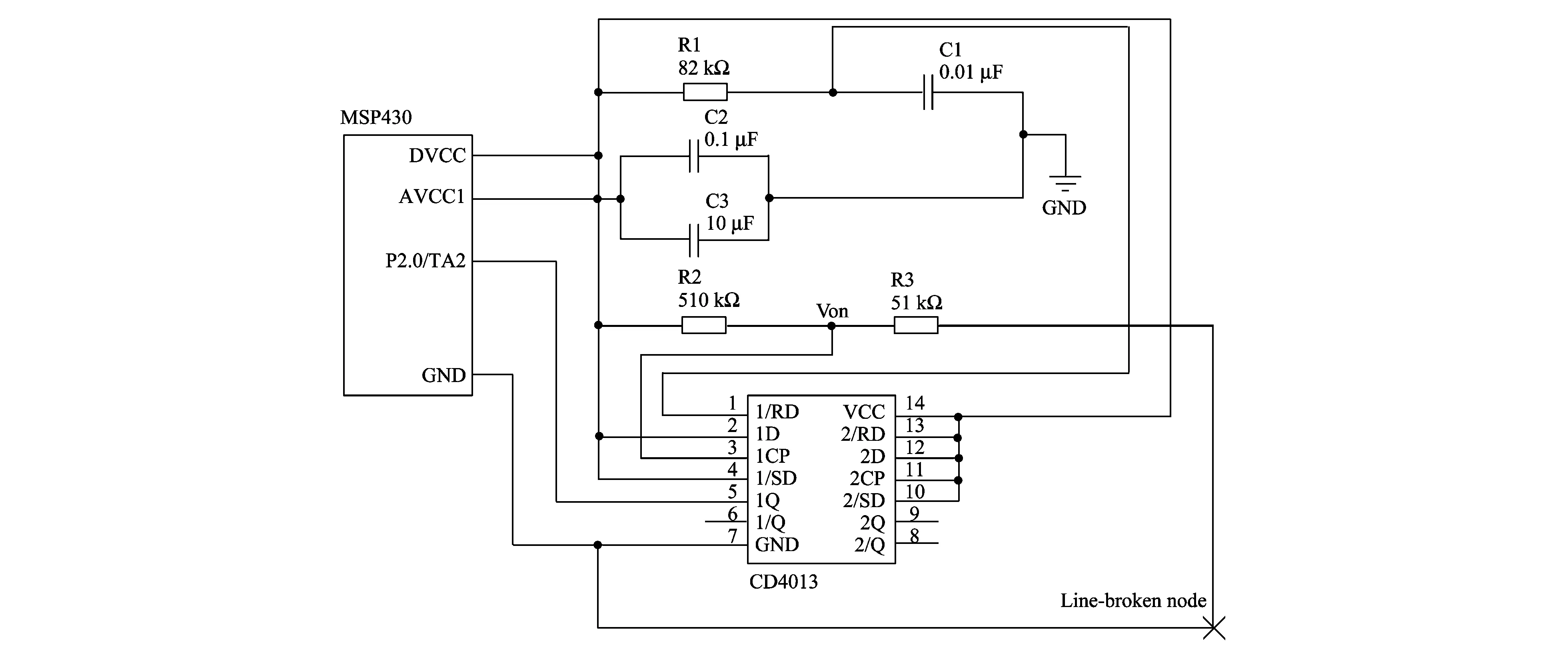
Fig.3 Schematic of broking line to power up
2 Theoretical analysis of explosion gas pressure from cluster bombs’ centre tube
For centre tube explosion dispersion, it explodes in a flash and generates an average pressurePm, which makes centre tube keep expanding.The radius at blasting moment isr1, then, the pressurePnat blasting moment is presented by
(1)
wherePm=ρ0D2/(γ1+1)≈0.28ρ0D2;ρ0is explosive density (kg/m3);Dis explosive speed (m/s);r0is initial radius of centre tube;r1is radius at blasting moment of centre tube;γ1is average polytropic exponent value of detonation products in centre tube, which is relevant to property, position and time of explosive[6].The ratio ofr1andr0can be calculated by
(2)
whereσsis allowable pressure of centre tube.According to the experimental test range,Pm=2 000 Mpa.Pnshown in Table 2 is the pressure at blasting moment under different settings ofr1/r0andγ1.

Table 2 Theoretical value of Pn under different parameters
Detonation products of center tube explosion generate pressure on dispenser and its shell and skin.PRis gas pressure at this moment, it can be calculated by
(3)
wherePRis expansion pressure of gas at radiusR[6].IfRis inner radius of dispenser,PRis final pressure, which directly acts on inner surface of bomb skin, as shown in Fig.4.
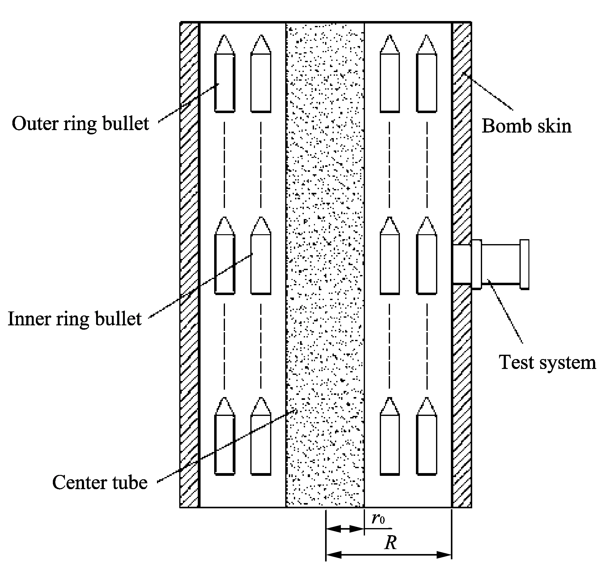
Fig.4 Schematic diagram of warhead


Table 3 Theoretical value of PS under different parameters
3 Analysis of field-test result
The gas pressure test system for storage-type cluster bombs and static dispersion test result of warhead with certain parameters are shown in Figs.5-6.
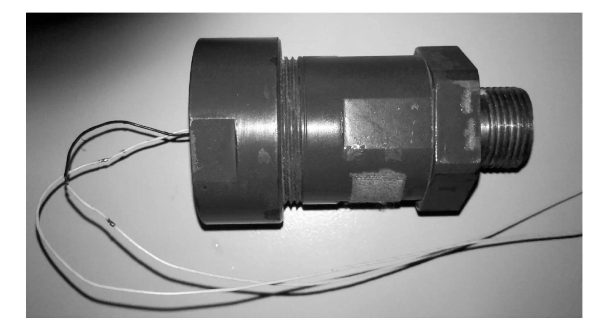
Fig.5 Gas pressure test device for storage-type cluster bombs
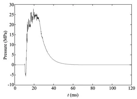
Fig.6 Static dispersion test result of gas pressure test system
The test result demonstrates that the peak value of gas pressure is about 25 Mpa, which is similar to theoretical value in case of the same parameters.It perfectly shows the changing process of gas pressure when cabin is opened.It is also a valuable basis for materials of centre tube, amount of gunpowder, size, material selection and inner structure of bombs.
4 Conclusion
The paper proposes a storage method of gas pressure for cluster bombs dispersion.Experiments show that the method brilliantly accomplishes storage and test in harsh environments, and stores the changing process of gas pressure in opening.It has such characteristics as easy to use, low power consumption, and strong anti-interference capability.The problem of poor reliability in traditional test and probability of explosion are overcome.The method has a good application prospect and popularization value in other explosion test fields.
[1] ZHANG Shou-zhong.Explosion and shock dynamics.Beijing: Weapon Industry Press, 1993.
[2] LI Ji-qi, MA Su-zhen.Explosion mechanics.Beijing: Science Press, 1992.
[3] ZU Jing, ZHANG Zhi-jie, PEI Dong-xing, et al.New concept dynamic test.In: Proceedings of the 12nd International Symposium on Test and Measurement, Beihai, China,2004.
[4] SHEN Jian-hua, YANG Yan-qin.MSP430 series 16 bits ultra-low-power MCU principles and practice.Beijing: Beijing University of Aeronautics and Astronautics Press, 2008.
[5] ZHANG Yu, ZU Jing, ZHANG Hong-yan.Environmental factors calibration technology of weapon chamber pressure test system.Fire Control & Command Control, 2012, 37(9): 209-214.
[6] JIN Jian-ming, CHANG Jin-zhen.Fragments dispersion velocity calculation of warhead with explosion of center tube cracking the case.Journal of Projectiles, Rockets, Missiles and Guidance, 2008, 28(1): 105-108.
 Journal of Measurement Science and Instrumentation2014年1期
- Journal of Measurement Science and Instrumentation的其它文章
- Error separation in CMM coordinate metrology
- A new probe for atmospheric electric field mill
- Experimental analysis of high temperature capacitance variance of MLCC
- Application of RLS adaptive filtering in signal de-noising
- QIM digital watermarking based on LDPC code and message passing under scaling attacks
- Energy-aware cooperative spectrum sensing for underground cognitive sensor networks
