Experimental analysis of high temperature capacitance variance of MLCC
WANG Feng, ZHAO He-ming
(College of Mechatronic Engineering, North University of China, Taiyuan 030051, China)
Miniaturization, lightweight and thinness of the electrical device make the electrical components be liable to become more miniaturized and complicated, and have the characterisics of light weight, multi-function, high reliability and long span[1,2].When surface mounting technique and surface mounting components (tandem) are quickly applied in the design of electrical products, because of new-type tandem components and rapid update, stability of the whole system will be affected if the designer does not fully understand the knowledge of performance parameters of the device and simply applies it in electrical products design[1].
Multi-layer ceramic capacitor (MLCC) is one of the most extensive tandem components[3,4].It has been applied in the complex integrated circuits on a large scale as external components and in the electrical devices requiring high reliability and miniaturization[5].The characteristics and high-temperature failure mechanism of MLCC will be introduced in this paper.
Elimination of MLCC down-lead leads to performance improvement and strict facture process, which can improve performance, reliability and life-span of MLCC.For example, small distributed capacitance and parasitic inductance of down-lead make MLCC have good frequency characteristics in quite broad frequency range.Tandem radio frequency(RF)/microwave MLCCs have been produced by American ATC, MDI, DLI, AVX and JFD companies.Inherent resonant frequency of 1-10 pF of MLCC can reach up to 2-10 GHz; 0.1-l pF, up to 15 GHz.MLCC can be directly welded with circuit boards, so MLCC can endure mechanical vibration and impulse, and mechanical, electrical and thermal performance and reliability of components are effectively improved through transferring the quantity of heat by components to circuit boards by down-leads.
MLCC has been applied to radio fuze and other fuzes at present[6].In electronic fuze, the capacitor is discrete component, thus it can be estimated that MLCC will be applied to electronic fuze more and more extensively.
1 Structure of MLCC
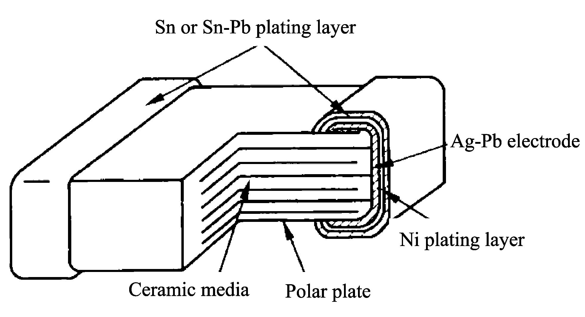
MLCC is made by coating ramic body with metal electrode slurry, which is agglomerated by interpolating and folding medium and plate layers (there are not gaps between ceramics and ceramics, ceramics and plates).Generally, the plate layer number is 2-3, sometimes up to ten or hundred, which makes the capacitor have bigger specific volume.For example, the specific volume of MLCC with 1 μF can reach up to 140 μF/cm3, and its stability is higher.Fig.1 shows the structure of a type of MLCC, which is rectangular non-down-lead structure (other tandem capacitance is quasi-rectangular structure) at high temperature.The present MLCC capacitors include 1206, 0805, 0603, 0402, 0201, etc., of which sizes are small and the capacitance value is related to the thickness in similar size.

Fig.1 Structure of MLCC
2 Effect of high temperature on working reliability of MLCC
Conventional MLCCs can be classified into two types: high frequency MLCC and low frequency MLCC.High frequency MLCC has very small dielectric constant(εr=6-450) with small capacitance value (1 pF-10 nF), relatively small change of dielectric constant with temperature, and the maxium allowable deviation is ±1%-±5%.Therefore, it can be used in high temperature stability situation.Low frequency MLCC has very big dielectric constant(εr=700-50 000), with big capacitance value (0.01-2.2 μF) and relatively obvious change of dielectric constant with temperature, and the allowable deviation is ±10%-±20%.Some temperature coefficients are plus but some are minus according to different materials and manufacturing technologies.So the allowable deviation is between ±10%-±50%, and it cannot be used in precise devices.
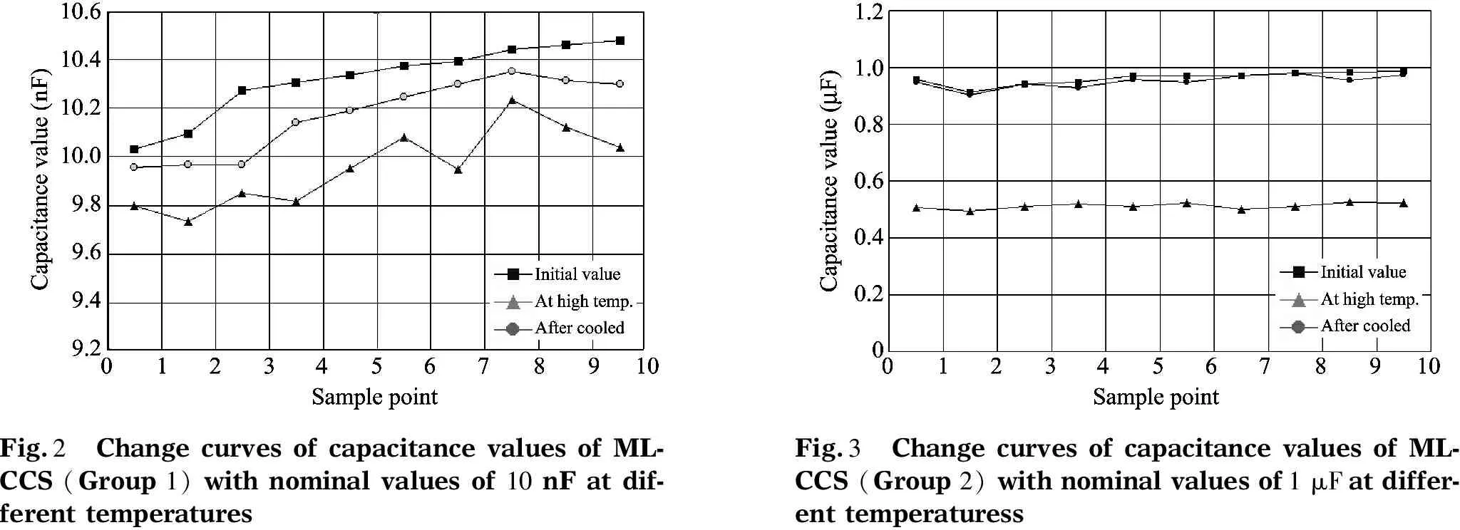
At present, many companies around the world produce MLCCs with different materials and manufacturing technologies.MLCCs with high frequency of 10 nF and low frequency of 1 μF (20 samples in all) manufactured by the same company are used in high temperature and constant stress experiment using thermostat with constant temperature at 70 ℃ for continual 24 hours.In this process, external connection lead can be used to measure components in real time.Experimental results are shown in Table 1, Table 2, Fig.2 and Fig.3.

Table 1 Experimental results of MLCCs (Group 1) with nominal values of 10 nF

Table 2 Experimental results of MLCCs (Group 2) with nominal value1s of 1 μF

Fig.2 Change curves of capacitance values of ML-CCS (Group 1) with nominal values of 10 nF at dif-ferent temperaturesFig.3 Change curves of capacitance values of ML-CCS (Group 2) with nominal values of 1 μF at differ-ent temperaturess
Itcanbeseenthatchangerateofthecapacitancevaluesis-3.5%athightemperaturerelativetotheinitialvaluesfromthesamplesofGroup1;itis-46.86%fromthesamplesofGroup2,whichmaybecausedbyparameterdrift.Thereasonisthattemperaturestabilityoftheconventionalceramiccapacitorisinverselyproportionaltodielectricconstant,thatistosay,thebiggercapacitancevalueofceramiccapacitor,theworsetemperaturestability.Theexperimentalresultsshowthattheparametersofcapacitancecannotfullyrecovertotheinitialvalueafterhightemperature,whichindicatesthatthecomponentparametersarenotstable.
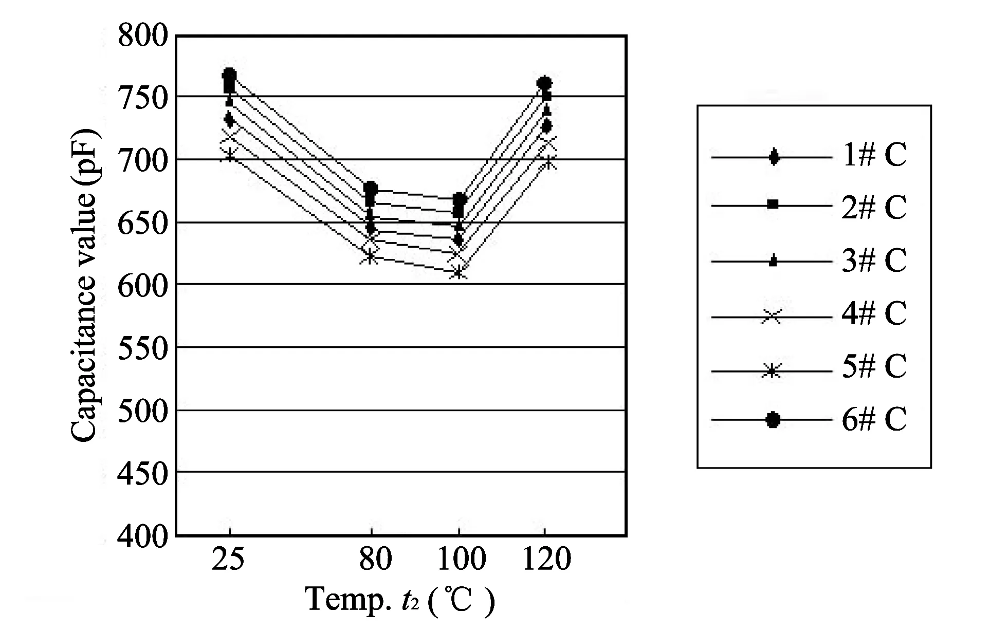
Experimentalresultsofthehightemperaturestepstresstestof6MLCCs(Group3)areshowninFig.4.Itcanbeseenthatcapacitancevariationwithtemperatureisa“funnel”.Theminimumvalueoccursat80or100 ℃,butthegeneraltrendisthatcapacitancevaluedecreaseswiththetemperatureincreasing.Therefore,tomeettherequirementswithin120 ℃,theminimumvalueshouldbeat80 ℃.Thisruleisappliedtothetesttoreducethenumberoftests,suchasthoseonly20-80 ℃or20-100 ℃,whichcanimprovetestefficiency.

Fig.4 Experimental result of MLCCs (Group 3)
3 Conclusion
The capacitance value of low frequency MLCC is largely affected by temperature seen from the above experiments, which can lead to instability of the whole equipment.Here are some suggestions proposed for reference if MLCC is applied to electrical products:
1) MLCC standards from different countries can be used for references.At present, MLCC components around the world have full standards, for example, IEC 384-10,EIA-198, MIL-C-55681, CECC32100, JIS-C-6429, etc.And procurement specification and samples have been established by such companies from Tomson, Phillip, Pisonic, etc.Similar and equivalent standards (GB/T 9324-1996, GJB-192A-1998) are also established in China according to international standards and advanced standards.
2) Allowance is left in design before using MLCC according to allowed warp, because there exists more or less change in MLCC capacitance with the change of environment.
3) High frequency MLCC is comparatively suitable for the miniaturized system.
4) Some low frequency MLCCs are not suitable for precise devices, which can be replaced by tandem Tantalum(Ta) electrolyte capacitance and multi-player talc capacitance with stable performance if necessary, as well as note the environmental temperature.
[1] ZHANG Chang-reng.The discussion on some questions in MLCC.Electronic Components and Materials,1999, 4: 1-8.
[2] DONG Ming-he, ZHOU Dong-xiang, GONG Shu-ping.Review on development of multi-layer chip devices, Journal of Materials, 2000, (10): 33-35.
[3] JIN Tong-shou.Resistance and capacitance components and tandem technology.Nanjing: South-east University Publishing House, 2000: 5.
[4] WANG Shao-hong, ZHOU He-ping, LUO Ling-hong, et al.Research and development of multilayer chip inductors and materials.Materials for Mechanical Engineering, 2002, (12): 1-5.
[5] SUN Qing.Reliability engineering of electronic components.Beijing: Electronic Industry Publishing House, 2002: 8.
[6] XIANG Yong, XIE Dao-hua.The application of new-type components in electronic information domain.Electronic Components and Materials, 2001, (6): 16-18.
 Journal of Measurement Science and Instrumentation2014年1期
- Journal of Measurement Science and Instrumentation的其它文章
- Error separation in CMM coordinate metrology
- Design and theoretical analysis of test system for propellants’ gas pressure in warhead
- A new probe for atmospheric electric field mill
- Application of RLS adaptive filtering in signal de-noising
- QIM digital watermarking based on LDPC code and message passing under scaling attacks
- Energy-aware cooperative spectrum sensing for underground cognitive sensor networks
