下颌后牙单端桥基牙骨支持组织应力的动力学分析*
黄 珊, 唐 亮, 潘燕环, 殷仲达
(暨南大学1附属第一医院口腔科,2医学院口腔医学系,3理工学院土木工程系,广东 广州 510632)
1000-4718(2012)03-0524-04
2011-11-20
2011-12-27
广东省自然科学基金资助项目(No.31912)
△通讯作者 Tel:020-38688114;E-mail:ttliang@jnu.edu.cn
下颌后牙单端桥基牙骨支持组织应力的动力学分析*
黄 珊1, 唐 亮2△, 潘燕环3, 殷仲达2
(暨南大学1附属第一医院口腔科,2医学院口腔医学系,3理工学院土木工程系,广东 广州 510632)
目的建立下颌后牙单端固定桥及其支持组织的三维有限元模型,采用瞬态动力学分析,比较单端桥修复前后基牙骨支持组织的应力分布规律。方法用ANSYS 10.0软件对模型施以不同部位和方向的冲击载荷,分析单端桥基牙骨支持组织的应力大小、分布及变化规律。结果斜向载荷下,基牙骨支持组织存在明显应力集中;单端桥修复后,应力峰值77.676 MPa位于近缺隙侧基牙的皮质骨颈部;一个咀嚼周期末存在应力残余,其值不显著。结论单端桥近缺隙侧基牙承受主要应力,载荷方向影响应力大小及分布,应力峰值小于下颌骨应变极限强度。
单端桥; 牙槽骨; 动态载荷; 三维有限元法; 应力
游离缺失牙的患者经单端桥修复,牙会以桥体为力臂产生I类杠杆作用,损害基牙的牙周健康。目前对单端桥应用的合理性仍有争议[1]。本研究采用有限元法模拟分析动态载荷下单端桥基牙骨支持组织的应力大小及变化规律,为单端固定桥的设计和临床应用提供生物力学参考依据。
材 料 和 方 法
1有限元模型建立

2实验条件的假设
将模型中各种材料和组织考虑为连续、均质、各向同性的线弹性材料。各组织动力学参数选自相关文献[2-3]。牙槽骨近远中径及底部完全固定,即X、Y、Z 3个方向均受约束;牙槽骨颊舌侧为自由边界,不受任何方向的约束。受力时模型各界面均不产生相互滑动。
3加载条件
3.1加载量 250 N。
3.2加载部位和方向 设定载荷为动态载荷,载荷为点加载。
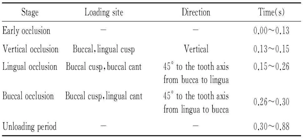
3.2.1垂直加载 与牙体长轴一致,集中载荷于下颌后牙颊尖和舌尖,见表1。
3.2.2斜向加载 自颊侧向舌侧与牙体长轴成45°,集中载荷于颊尖颊斜面;自舌侧向颊侧与牙体长轴成45°,集中载荷于颊尖舌斜面,见表1。
3.3加载时间 选取一个正常咀嚼周期0.88 s,按不同时间牙合力变化将其分为5个时段:0.00~0.13 s咬合前期; 0.13~0.15 s垂直咬合期; 0.15~0.26 s舌向咬合期;0.26~0.30 s颊向咬合期;0.30~0.88 s卸载期,见表1。为比较应力-时间曲线变化,选择3个连续咀嚼周期进行研究,分析应力积累。
表1一个咀嚼周期0.88s内动态加载的阶段、部位、方向和作用时间
Table 1. The dynamic loading stage, site,direction and time in a masticating cycle

StageLoadingsiteDirectionTime(s)Earlyocclusion--0.00~0.13VerticalocclusionBuccal,lingualcuspVertical0.13~0.15LingualocclusionBuccalcusp,buccalcant45°tothetoothaxisfrombuccatolingua0.15~0.26BuccalocclusionBuccalcusp,lingualcant45°tothetoothaxisfromlinguatobucca0.26~0.30Unloadingperiod--0.30~0.88
4统计学处理
采用秩和配对法检验分析,按α=0.05水准,用SPSS软件分析各基牙骨支持组织应力值冯·米塞斯(von Mises)值在修复前后的差异。
结 果
1三维有限元模型

2修复前、后基牙最大vonMises值

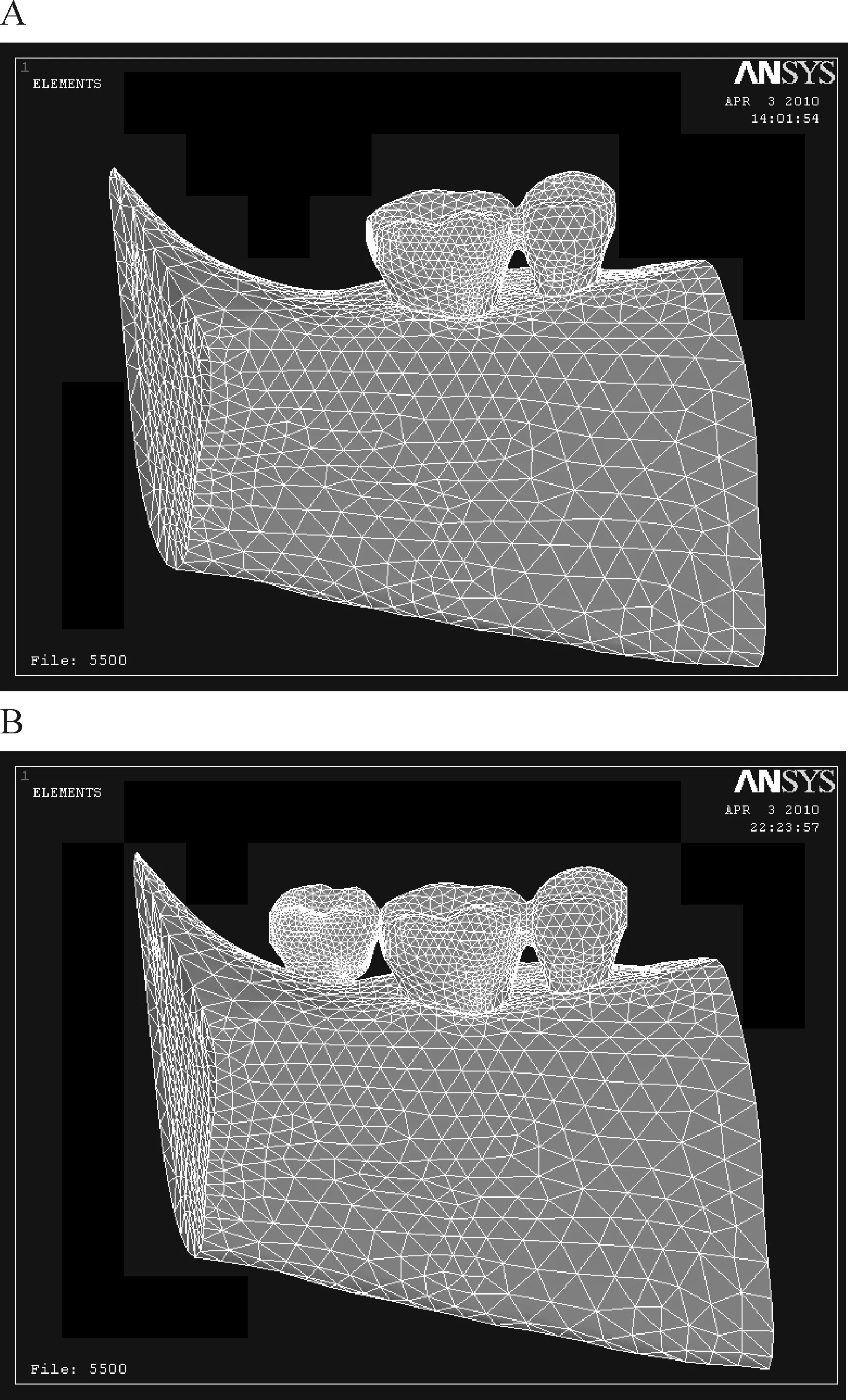
Figure 1. The finite element models before (A) and after (B) repairing.
图1修复前、后的有限元模型
表2单端固定桥修复前、后划分节点及单元数目
Table 2. The node and unit numbers before and after repairing with cantilever fixed partial denture

ItemToothPeriodontalligamentCorticalboneCancellousboneTotalBeforeAfterBeforeAfterNode3359444942353211650684277169698181046Unit2891338476338151722569744149697159260
表3修复前、后基牙最大vonMises值
Table 3. The maximum von Mises value on abutments before and after repairing (MPa)

Tooth0.15s0.26s0.30s0.88sBeforeAfterBeforeAfterBeforeAfterBeforeAfter534.85022.68934.78248.54847.41524.1178.9437.783619.36156.37734.78277.67636.46976.8787.45720.766


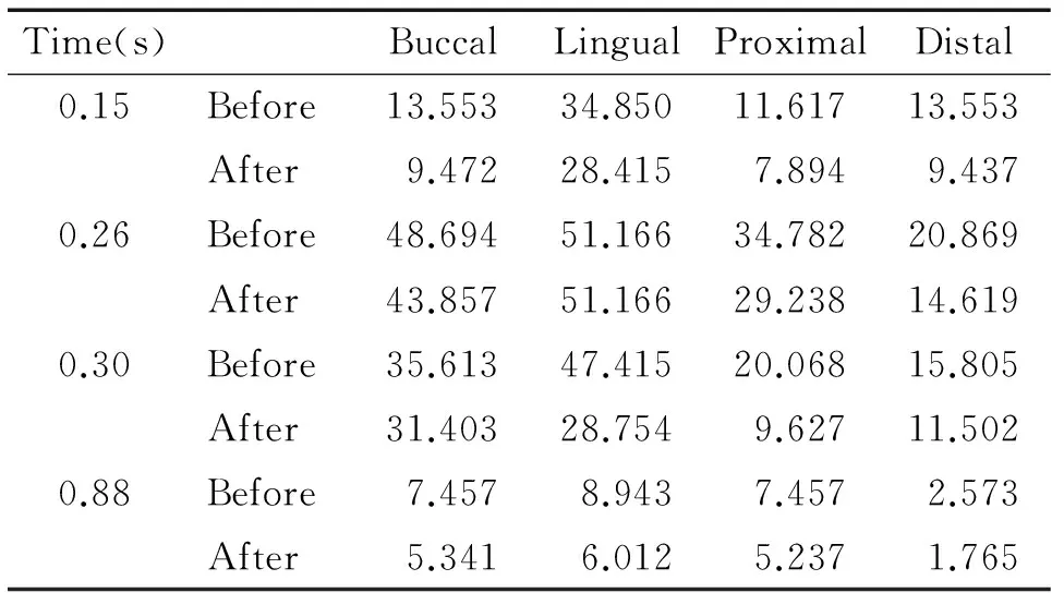
Time(s)BuccalLingualProximalDistal0.15Before13.55334.85011.61713.553After9.47228.4157.8949.4370.26Before48.69451.16634.78220.869After43.85751.16629.23814.6190.30Before35.61347.41520.06815.805After31.40328.7549.62711.5020.88Before7.4578.9437.4572.573After5.3416.0125.2371.765


Time(s)BuccalLingualProximalDistal0.15Before11.61719.3617.7459.681After9.47218.9445.7479.4720.26Before34.78230.9776.9774.323After43.85736.5477.32112.6770.30Before36.46915.80510.5375.268After48.00617.2528.6425.7510.88Before6.4577.4572.3763.729After8.0128.3412.5415.282
4修复后残余应力大小


讨 论
1动态加载方案
资料显示, 正常咀嚼运动一个周期内, 牙齿咬合接触时间平均为0.2 s[4],故本研究取一个咀嚼周期为0.88 s,将其分为5个阶段。力学上认为任何物体受力处总会是一个面,在咀嚼过程中磨牙受力集中到一点的情况几乎不存在。本实验在不同阶段,设计不同牙位的点接触,相对符合口腔咀嚼情况。
2应力分析指标
力的方向及分布是造成创伤性骨吸收的主要因素。牙槽骨的吸收程度与最大牙合力值间存在明显的相关性。von Mises应力是各应力综合作用的结果,反映了物体整体的强度要求,常用作衡量应力水平的主要指标[5],该值可以清晰描述出一种结果在整个模型中的变化,从而快速确定模型中最危险的区域。
3单端固定桥修复前、后基牙骨支持组织应力变化分析


3.23个咀嚼周期的应力-时间曲线变化分析 牙合力为一种交变应力,具有周期性变化规律[8]。当材料受到交变应力作用时,即使应力低于屈服极限,发生在材料某处局部的损伤递增过程经应力和应变循环后,损伤累积也会使材料发生突然病损[9]。单端桥修复后,3个咀嚼周期的应力峰值逐渐有所上升,提示有应力积累,若连续咬合多个周期,反复载荷下有发生损伤的可能。但有资料指出, 正常咀嚼运动一个周期内, 牙齿咬合接触时间仅为0.2 s[4],显示实际情况中连续载荷并不出现,且牙周膜中有丰富的末梢神经和胶原纤维,可以支配颌骨、肌和关节的运动,有调节和缓冲咀嚼力的功能。临床单端桥修复后,须注意患者偏侧咀嚼问题,以免咀嚼周期过于频繁。由此可见,在合理选择基牙的情况下,后牙单端桥的设计是可行的。
综上所述,单端桥修复后近缺隙侧基牙承受主要应力,载荷方向影响应力大小及分布,单端桥应力峰值小于下颌骨应变极限强度。本实验在生物力学角度支持单端桥修复。在今后的研究中,将尝试建立更加精确的模型,使组织动力学参数多元化,完善加载条件等,以使研究向生物仿真方向发展。
[1] Anderson JD.Ten-year survial rate for cantilevered fixed partial denture[J].Evid Based Dent,2005,6(4):96-97.
[2] Sorrentino R,Aversa R,Ferro V,et al.Three-dimensional finite element analysis of strain and stress distributions in endodontically treated maxillary central incisors restored with different post, core and crown materials[J].Dent Mater,2007,23(8):983-993.
[3] Huang HM,Tsai CY,Lee HF,et al.Damping effects on the response of maxillary incisor subjected to a traumatic impact force:a nonlinear finite element analysis[J].J Dent,2006,34(6):261-268.
[4] Paphangkorakit J,Osborn JW.The effect of pressure on a maximum incisal bite force in man[J].Arch Oral Biol,1997,42(1):11-17.
[5] Aboushelib MN,Jager N,Kleverlaan CJ,et al.Effect of loading method on the fracture mechanics of two layered all-ceramic restorative systems[J].Dent Mater,2007,23(8):952-959.
[6] 薄 斌,周树夏.人下颌骨在不同应变率下的拉伸强度[J].实用口腔医学杂志,1999,15(6):417-418.
[7] 张新春, 陈慧芝, 滕 伟, 等.动态载荷下三种形式箍效应的有限元分析[J]. 南方医科大学学报,2008,28(9):1646-1648.
[8] Hanck JE,Sakaguchi RL,Sun T,et al.Elongation and preload stress in dental implant abutment screws[J].Int J Oral Maxillofac Implants,1995,10(5):529-536.
[9] 王 革,程详荣.三维有限元动态分析不同螺距的两种螺纹种植体的应力分布[J].实用口腔医学杂志,2002,16(3):214-216.
Adynamicfiniteelementanalysisofstressdistributioninsupportingboneofmandibularcantileverfixedbridgeabutment
HUANG Shan1, TANG Liang2, PAN Yan-huan3, YIN Zhong-da2
(1DepartmentofStomatology,TheFirstAffiliatedHospital,2DepartmentofStomatology,SchoolofMedicine,3DepartmentofCivilEngineering,CollegeofScienceandEngineering,JinanUniversity,Guangzhou510632,China.E-mail:ttliang@jnu.edu.cn)
AIM: To analyze the stresses induced in the supporting bone tissue of the fixed partial denture abutment in the mandible under transient dynamic loads.METHODSA three-dimensional model was generated. Finite element analysis was performed on the model under dynamic loads in various directions and positions in a masticating cycle to study the magnitude and distribution of the stresses in the supporting bone of abutments.RESULTSOblique loads tended to produce more stress concentration. The peak stress value was 77.676 MPa at the neck of cortical bone with cantilever bridge. The residual stress in alveolar bone was not obvious in a masticating cycle.CONCLUSIONThe stress on the abutment nearest to the pontic is the highest. The loading direction affects the magnitude and distribution of stresses. The peak stress value is less than the strain limit of mandible.
Cantilever bridge; Alveolar bone; Dynamic load; Three-dimensional finite element method; Stress
R783.3
A
10.3969/j.issn.1000-4718.2012.03.024

