A dual-frequency orthogonal-bi-polarization laser cavity based on a photonic crystal†
2011-05-12 07:56OUYANGZhengbiaoCAOEnwenandLIChengkuan
深圳大学学报(理工版) 2011年4期
OUYANG Zheng-biao,CAO En-wen,and LI Cheng-kuan
College of Electronic Science and Technology THz Technical Research Center of Shenzhen University Shenzhen Key Lab of Micro-Nano Photonic Information Technology Shenzhen University Shenzhen 518060 P.R.China
A dual-frequency orthogonal-bi-polarization laser cavity based on a photonic crystal†
OUYANG Zheng-biao,CAO En-wen,and LI Cheng-kuan
College of Electronic Science and Technology THz Technical Research Center of Shenzhen University Shenzhen Key Lab of Micro-Nano Photonic Information Technology Shenzhen University Shenzhen 518060 P.R.China
With an anisotropic defect layer in a one-dimensional photonic crystal,a dual-frequency orthogonal-bipolarization laser cavity is presented.It is demonstrated through 4×4 transfer matrix method that such a cavity does have two orthogonally polarized resonance modes.The frequency difference of the two modes can be efficiently controlled by rotating the optical axis of the anisotropic defect layer in the cavity.The condition for maintaining the two modes to exist simultaneously is to have approximately an equal optical gain for both of the two modes in the active cavity.It is found that equal optical gain for the two modes can be obtained by controlling the concentration of gain material in the defect layer in the active cavity.The influences of the orientation of optical axis and the number of periods around the defect layer on operating parameters in the active cavity are also studied.Such a cavity is different from conventional ones for its small size with thickness in a few micrometers and large tunable frequency difference from 0 to 199.8 GHz.
lasers;laser resonators;photonic crystals;double-wavelength;orthogonal polarized modes;mode competition
Dual-frequency lasers have a wide range of applications,e g,in measuring angles[1-2],micro movement[3],retardation of wave plates[4], pressure[5], gravity[6]and weak magnetic field[7-8]based on light interference.Commonly used dual-frequency lasers are He-Ne lasers based on the longitudinal Zeeman Effect.Its frequency difference(FD),however,can not be greater than 3 MHz[9],which severely limits the measuring speed of the dual-frequency laser interferometer.To solve this problem,some scientists put quartz crystal[2,9]and KD*P[10]in an ordinary He-Ne laser cavity.Because of the birefringence,such a laser is named as birefringence dual-frequency laser,in which o-and elight waves will be produced,and the orthogonal-bi-polarization(OBP)resonance modes with their FD up to hundreds of MHz would be obtained[11].Yet,due to the limitation in the bandwidth of the light gain in He-Ne lasers,the maximum FD of these lasers would be no more than 1.5 GHz[12].In order to improve the measuring accuracy and speed,a dual-frequency laser with its FD in dozens of GHz,hundreds of GHz or even greater values become a research hotspot[12].Furthermore,conventional dualfrequency birefringence lasers are large in size and high in pump power,lifting their cost and limiting their applications.
With the bringing forth of photonic crystals(PhCs),which have photonic bandgaps,in 1987 by Yablonovitch E[13]and John S[14],micro cavities based on PhCs with defect have attracted much attention[15-20].These cavities are very small in volume(cubic micrometers).Furthermore,they need very low optical pump power(micro watts)[21], and even a laser with no threshold pump power can be built through appropriate design of the resonant cavity[22].
In this paper,by applying birefringent material as a defect in a PhC,we present a laser cavity with which a dual-frequency OBP laser can be built.Such a laser has a large FD,a low threshold of pump power and a small volume.We find that the FD of the OBP defect modes can be efficiently controlled by rotating the optical axis of the birefringent defect layer.With a gain material doped in the defect in the cavity,the condition and method for setting up the oscillation of the OBP modes in the system simultaneously are also studied.For consideration of applications,simulations are shown for a micro cavity working in the optical communication wave band with large FD.
1 Physical model and method of calculation
1.1 Physical model
The schematic of the cavity studied in this paper is shown in Fig 1.The structure of the one-dimensional(1-D)PhC in Fig 1 is(AB)ND(BA)NwithNstands for the number of periods.In Fig 1,the layer filled with solid-line pattern stands for medium A with low refractive index,the layer filled with short-dash-line pattern stands for medium B with high refractive index,and the black layer stands for the anisotropic medium D which is the defect layer in the PhC.All the mediums in the structure are considered to be non-dissipative,non-dispersive and non-magnetic.We express the wavelength of the bandgap center as λc,the refractive index and the width of the layer with high refractive index asnbandLb=λc/(4nb),and the refractive index and width of the layer with low refractive index asnaandLa=λc/(4na).For simplicity,the medium for the defect layer is taken to be a uniaxial crystal,whose optical axis is in general parallel to thex-axis,withnoandneas its spindle refractive indexes,andLd=λc/(4no)as its width.

Fig.1 Schematic of the one-dimensional PhC OBP cavity.图1 一维光子晶体偏振正交双色腔结构示意图
1.2 Method of calculation
The main methods for studying the band structure and transmission characteristics of PhCs are:the plane wave expansion method[23-25],the finite-difference time-domain method[26-29]and the transfer matrix method[30].Among them,the transfer matrix method has a great advantage in studying 1-D PhCs.In this paper,a 4 × 4 transfer matrix method followed Berreman[31]is used to study the transmission characteristic of the 1-D PhCs with an anisotropic defect layer.For convenience,we here give a profile of the method.
1.2.1 Conversion of Maxwell's equations into matrix form
In the Gaussian system of units,Maxwell's equations in passive mediums are:
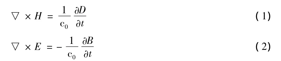
where c0,E,D,H and B are the speed of light in vacuum,the electric field intensity vector,the electric displacement vector,the magnetic field strength and the magnetic induction intensity vector,respectively.The matrix form of Eq(1)and Eq(2)is:

and M is a matrix decided by material parameters.In Eq(4),∂x,∂yand ∂zare defined as∂x=∂/∂x,∂y=∂/∂yand ∂z=∂/∂z,respectively.
Assuming the time factor of electromagnetic fields to be exp(iωt),i e,W=Γexp(iωt),from Eq(3)we can obtain:

where Γ=[Γ1Γ2Γ3Γ4Γ5Γ6]T.The elements of Γ are the complex amplitudes of field components and the superscript T indicates the transpose of matrix.
Using Eq(6)to eliminate Γ3and Γ4,we can simplify Eq(3)to be
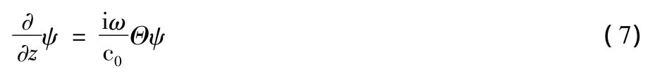
where

and Θ is a 4 × 4 matrix,whose elements are determined by Eq(3)and Eq(6).
1.2.2 Solution of the matrix differential equations
Assume that the parameters in the matrix in Eq(7)are not related toz,i e,the dielectric constant and magnetic permeability tensor of the mediums do not change withz,and then we have the following form of solution for Eq(7):

whereqjis the eigenvalue of the matrix iωΘ/c0.The eigenvectors ψj(j=1,2,3,4)can be obtained from the equation Det(iωΘ/c0-qjI)=0.
Suppose the field atz=z0is the superposition of the four eigen vectors,i e,Ψ(z0)=∑ajψj(z0)which can be written as

whereA{aj,j=1,2,3,4}is a column vector of the superposition coefficients,which express the polarization of the electromagnetic wave.So the field atz=z0+hwould be

where Q is a diagonal matrix withQjj=exp(iqjh).From Eq(9)to Eq(11)we have:

From Eq(12),the transfer matrix for light transmitting through the dielectric layer with thicknesshcan be written out to be

1.2.3 Calculation of reflectance and transmittance
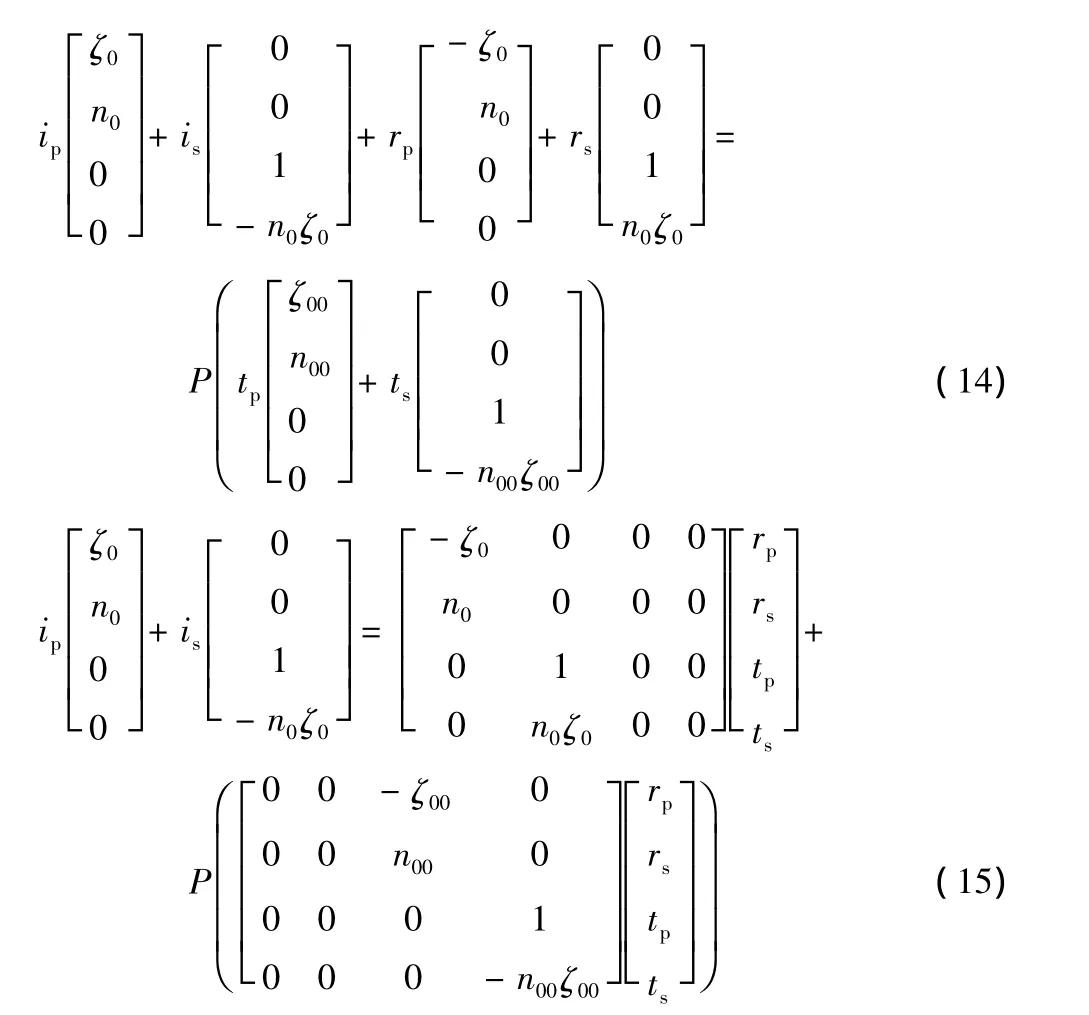
Supposing the incident wave is linearly polarized,we can decompose the wave into two parts:s-polarization wave(simplified as s-wave for brevity in the following)whose polarization or electric intensity vector E with intensityisis parallel to they-axis,corresponding to the o-light in the anisotropic medium,and p-polarization wave(simplified as p-wave for brevity in the following)whose electric intensity vector E with intensityipis in the planexoz,corresponding to the e-light in the anisotropic medium.We indicate the electric intensity of the reflected and transmitted s-wave byrsandts,the electric intensity of the reflected wave and transmitted p-wave byrpandtp,and use P to describe the transfer matrix for the whole structure.Hence:

2 Simulation results and analysis
2.1 Defect modes in a passive OBP cavity
In this paper,the transmittance spectra of the 1-D PhC OBP cavity with real dielectric constant(passive cavity),i e,without gain material,are studied at first.The parameters are chosen as follows:n0=n00=1,na=1.73(Ca3Al2Si3O12),nb=4.02(GaAs),λc=1.55 μm,La=λc/(4na),Lb=λc/(4nb),no=1.65,ne=1.647(Ca5(PO4)3Cl)andLd=λc/(4no).A linearly polarized incident light,whose polarization is at an angle of 45°deviated from thex-axis clockwise in planexoy,goes along thez-axis.Decomposing the incident light into s-and p-waves,we can obtain the transmittance spectrum,defined as transmittance versus wavelength,as shown in Fig 2.

Fig.2 Transmittance spectrum for the 1-D PhC passive OBP cavity.图2 一维光子晶体无源偏振正交双色腔的传输谱
We can see from Fig 2 that there are simultaneously OBP defect modes.The physics is that the refractive index of the anisotropic medium in the defect layer is different for the wave with different polarization.So the structure is equivalent to that with two different defects at the same time:one with the refractive index for o-light or s-wave,and the other one with the refractive index for e-light or p-wave.This leads to the existence of two defect modes simultaneously:s-mode,excited by the s-polarization component of input wave,and p-mode,excited by the p-polarization component of input wave.And it is easily known by perturbation theory that the wavelength of the p-mode is less than that of the s-mode as shown in Fig 2,because the refractive index for e-light is less than that for o-light.With such a cavity,a laser would emit simultaneously a pair of fundamental resonant modes with mutually orthogonal polarizations.
2.2 Control of the FD of defect modes in an OBP cavity
In practice,e g,in the measurement of micro displacement,we often need two resonant modes with different FD.According to the characteristics of anisotropic media,by rotating the optical axis we can obtain different refractive indexes for o-and elight and thereby change the FD of the defect modes.
For simplicity,we only consider the case in which the optical axis is in an angle θ from thex-axis on the planexoz.According to the symmetry of the structure,we only need to deal with the case that the optical axis deviates from thex-axis clockwise.Through calculating the transmittance spectrum,the wavelength of the defect modes versus θ can be found out,as shown in Fig 3.The parameters for Fig 3 are the same as that for Fig 2.Without loss of generality,here we just show the result in a passive OBP cavity.
It can be seen from Fig 3 that the wavelength λsof the defect s-mode is fixed at 1.55 μm,while the wavelength λpof the defect p-mode increases with θ and approaches to λsat θ=90°.The greatest FD for the two modes is Δv=199.8 GHz(or Δλ =0.001 6 μm)at θ=0°.Therefore,by rotating the optical axis of the birefringent defect layer,different FD of the OBP modes can be achieved.This result applies to a passive OBP cavity,as well as to an active OBP cavity.
2.3 Realization of equal gain for the OBP modes in an active cavity

Fig.3 The wavelength(λ)of the defect mode versus the angle(θ)of the optical axis in a photonic crystal passive OBP cavity.图3 光子晶体无源偏振正交双色腔的缺陷模波长与光轴角度的关系
Now we dope gain material Erinto the anisotropic medium in the defect layer and obtain an active OBP cavity.The way to express the doping in this paper is to add an imaginary part iγ to the spindle refractive indexesneandnoof the anisotropic medium.It is known,e g,from Ref[32],that the spontaneous-emission spectrum of Eris approximately independent of wavelength in the vicinity of 1.55 μm.So,taking into consideration that the system operates in the vicinity of 1.55 μm,we can neglect the dispersion ofneandnoof the gain material.We define the gain of a cavity to be equal to its transmittance,which is defined at the end of section 1.2.3.It is found through research that the gain of defect modes does not vary with γ monotonously,as shown in Fig 4.From Fig 4,we can see that the gain reaches maximum at γs=-0.011 202 80 and γp=-0.011 162 14 for s-and p-modes,respectively.

Fig.4 The gain of the defect mode in the doped cavity versus γ for N=3 and θ =0°.图4 N=3,θ=0°时,掺杂腔中缺陷模的增益与γ的关系
The gain profile in Fig 4 can be understood by noting that,in a PhC,the gain and group velocity are closely related.Theoretically,it is known that,the smaller the group velocity is,the longer the interacting time between the radiation field and the media,and the higher the values of the corresponding gain.According to Ref[33],we can calculate the equivalent effective refractive indexneffof the PhC structure.Then we can obtain the equivalent group velocity index by the following formula,

Further,utilizing Eq(16)we can calculate the group velocity by

The calculated group velocity is indicated in Fig 5.From Fig 5,it can be seen obviously that the group velocity of the defect modes is several orders of magnitude less than the speed of light in vacuum.It can also be seen from Fig 5 that there are two points γ1=-0.011 21 and γ2=-0.011 16 at which the group velocity becomes zero and the absolute value of the group velocity increases as γ goes away from the two points.Since higher group velocity leads to shorter interacting time and lower optical gain,the result in Fig 5 gives a good explanation for that in Fig 4.
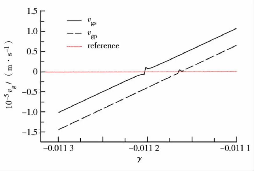
Fig.5 The group velocity versus γ.Parameters used are the same as that for Fig 4.图5 群速度与γ的关系
Furthermore,from Fig 4 we can see that equal gain for the OBP defect modes can be obtained only at the cross point(γ=γE=-0.011 182)of the two curves in Fig 4.For γ = γE=-0.011 182 and other parameters being the same as that for Fig 4,the gain spectrum,defined as gain versus wavelength,can be obtained,as shown in Fig 6,which demonstrates that the two modes do have equal gain.With equal gain,the OBP defect modes will grow and reach a steady state simultaneously in the laser cavity,eliminating mutual competitions between the two modes.

Fig.6 The gain spectrum of the 1-D PhC active OBP cavity with gain material doped in the defect layer for γ = γE=-0.011 182.图6 对于γ=γE=-0.011 182,缺陷层中掺杂增益材料的一维光子晶体偏振正交双色腔的增益谱
On the contrary,a single polarization mode can be obtained by eliminating the other defect mode through proper choice of doping concentration of gain material in the defect layer.
2.4 Influence of optical axis orientation and number of periods on performance of an active OBP cavity
For applications,it is necessary to investigate the influence of structure parameters on the performance of the OBP cavity.In the following,we focus on the influence of optical axis orientation and number of periods on it.
2.4.1 Influence of optical-axis orientation on performance of the active OBP cavity
TakingN=3 and the initial polarization angle of incident light to be 45°deviated from thex-axis,we obtain the result shown in Fig 7 by scanning the angle θ of optical axis.
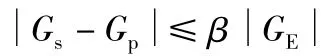
Figures 7(a)and 7(b)show that,both Δγ anddecreases with θ.Noting<0 and γE<0,the decrease ofmeans the increase ofand,i e,greater doping concentration of gain material in the defect layer is needed for larger θ.Figures 7(c)and(d)show that both the equal gainGEand quality factorQEincrease with θ.These results can be explained as follows.Because smaller group velocity leads to higher gain,from Fig 3 and Eq(16)and Eq(17)we can deduce that,as θ increases,the gain curve and its peak for s-mode in Fig 4 does not vary,while the curve and its peak for p-mode get closer to that for s-mode.As a result,the cross point of the two curves in Fig 4 moves toward left andGEincreases,which gives an expla-nation for the results in Fig 7(b)and Fig 7(c).With this in mind and referring further to Fig 4,we can see that the two peaks in Fig 4 for larger θ are steeper than that for smaller θ.Therefore,the allowed Δγ for larger θ is less than that for smaller θ,which agrees with the result in Fig 7(a).Finally,noting that larger θ corresponds to largerGE,hence higher oscillation amplitude of the defect modes and that the bandwidth of the modes is decided mainly by the periodic structure around the defect,and from the definition of quality factors,we can deduce that larger θ corresponds to higher quality factors,which agrees with the result in Fig 7(d).

Fig.7 Influence of optical-axis orientation on performance of the active OBP cavity.图7 光轴取向角对有源偏振正交双色腔性能的影响
2.4.2 The influence of lattice-period numberNon performance of an active OBP cavity
We have also calculated the influence ofNon Δγ,γE,GEandQEin an active OBP cavity,as shown in Fig 8.The influence ofNon these operating parameters originates from the fact that differentNleads to different localization of light in the cavity.
Figure 8(a)shows that Δγ decreases exponentially withN.Figures 8(b)and 8(d)show that both γEandQEincrease exponentially withN.While Fig 8(c)indicates thatGEincreases withN.These results can be easily understood as follows.It is well known that the localized field increases exponentially withNin a defect PhC,so that the height of the two curves in Fig 4 are both promoted exponentially asNincreases,and thus the peaks of the two curves in Fig 4 move closer correspondingly,leading to a rapid decrease of Δγ and a rapid increase of γEandGE.Also,the rapid increase of the localized field in the cavity withNleads to a corresponding increase of stored energy in the cavity and thus a rapid increase of quality factorGEof the cavity.

Fig.8 The influence of N on Δγ,γE,GE and QEin a 1-D PhC active OBP cavity.图8 一维光子晶体有源偏振正交双色腔中光子晶体周期数N对Δγ、γE、GE和QE的影响
Conclusions
By introducing an anisotropic defect layer in a 1-D PhC,we configured a dual-frequency OBP laser cavity.The cavity is demonstrated through 4×4 transfer matrix method to have OBP resonance modes.It is shown that the FD of the OBP modes can be efficiently controlled by rotating the optical axis of the birefringent defect layer in the OBP cavity.To maintain the two modes simultaneously,the optical gain for the two modes in the cavity should be about the same.We find that,equal optical gain for the two modes can be obtained by properly doping gain material in the defect layer in an active OBP cavity.The influences of the orientation of optical axis and the number of periods around the defect layer on operating parameters in an active OBP cavity are studied.For applications,simulations are shown for microcavities operating in the optical communication wavelength region near 1.55 μm.The proposed cavity is different from conventional ones for its very small volume(a few cubic micrometers)and large tunable FDs(0 ~ 199.8 GHz).
† This work was supported by the National Natural Science Foundation of China(60877034)and the Key Program of Natural Science Foundation of Guangdong Province(8251806001000004).
[1]ZHANG Shu-lian,LI Ke-lan,REN Ming,et al.Investigation of high-resolution angle sensing with laser mode-split technology[J].Applied Optics,1995,34(12):1967-1970.
[2]ZHANG Shu-lian,GUO Hui,LI Ke-lian,et al.Laser longitudinal mode splitting phenomenon and applications in laser physics and active metrology sensors[J].Optics and Lasers in Engineering,1995,23(1):1-28.
[3]ZHANG Shu-lian,LI Jia,HAN Yan-mei,et al.Study of displacement sensing based on laser mode splitting by intracavity quartz crystal wedges of HeNe lasers[J].Optical Engineering,1998,37(6):1800-1803.
[4] ZHANG Yi,ZHANG Shu-lian,HAN Yan-mei,et al.Method for the measurement of retardation of wave plates based on laser frequency-splitting technology[J].Optical Engineering,2001,40(6):1071-1075.
[5] HUANG Chun-ning,LI Yan,ZHANG Shu-lian,et al.Novel pressure sensor by diode-pumped birefringent Nd:YAG dual-frequency laser[C] //Proceeding of International Conference on Advanced Materials and Devices for Sensing and Imaging.Shanghai:SPIE,2002,4919:242-247.
[6]ZHANG Shu-lian,LI Da-cheng.Using beat frequency lasers to measure micro-displacement and gravity:a discussion[J].Applied Optics,1988,27(1):20-21.
[7]Zhang J,Feng T,Zhang S,et al.Measurements of magnetic fields by a ring laser[J].Applied Optics,1992,31(30):6459-6462.
[8]ZOU Da-tin,ZHANG Shu-lian,FENG Tie-sun,et al.The experiment study of the principle of weak magnetic sensor ring laser[J].Acta Optica Sinica,1988,8(12):1133-1138.(in Chinese)
[9]YANG Sen,ZHANG Shu-lian.The frequency split phenomenon in a He-Ne laser with a rotation quartz crystal plate in its cavity[J].Optics Communicatons,1988,68(1):55-57.
[10]ZHANG Shu-lian,LU Min,JIN Guo-fan.Laser frequency split by an electron-optical element in its cavity[J].Optics Communications,1993,96(4/5/6):245-248.
[11]ZHANG Shu-lian,XU Tin,LI Yan,et al.Principle and application of the orthogonal linearly polarized laser I[J].Progress in Natural Science,2004,14(2):145-154.(in Chinese)
[12]JIAO Min-xing,ZHANG Shu-lian,LIANG Jin-wen.Birefringence dual frequency Nd∶YAG laser with large frequency differences [J]. Chinese Journal of Lasers,2001,A28(2):100-102.(in Chinese)
[13]Yablonovitch E.Inhibited spontaneous emission in solid state physics and electronics[J].Physical Review Letters,1987,58(20):2059-2062.
[14]John S.Strong localization of photons in certain disordered dielectric superlattices [J].Physical Review Letters,1987,58(23):2486-2489.
[15]Altug H,Vuckovice J.Two dimensional coupled photonic crystal resonator arrays [J].Applied Physics Letters,2004,84(2):161-163.
[16]Herrmann R,Sünner T,Hein T,et al.Ultrahigh quality photonic crystal cavity in GaAs [J].Optics Letters,2006,31(9):1229-1231.
[17]XU Gui-wen,OUYANG Zheng-biao,AN He-nan,et al.The study of the band width and quality factor of the photonic crystal defect modes[J].Acta Photonica Sinica,2003,32(9):1079-1082.(in Chinese)
[18]OUYANG Zheng-biao,YANG Lin-ling,XU Gui-wen,et al.The study of the mode characteristics of the one-dimensional photonic crystal with defect[J],Journal of Optoelectronics·Laser,2005,16(1):63-66.(in Chinese)
[19]OUYANG Zheng-biao,XU Gui-wen,SUN Yi-ling,et al.Tuning characteristics of the photonic crystal micro cavity[J].Journal of Optoelectronics·Laser,2005,16(4):399-401.(in Chinese)
[20]XU Gui-wen,OUYANG Zheng-biao.A new type of photonic crystal cavity with two defect modes[J].Acta Photonica Sinica,2007,36(3):429-435.(in Chinese)
[21]Powell P M.Photonic crystal laser features low threshold pumping[J].Applied Physics Letters,2002,81(15):2680-2682.
[22]LIAO Xian-bing.Technology of photonic crystal-photonic crystal laser[J].Semiconductor Optoelectronics,2003,24(4):286-289.(in Chinese)
[23] Yee K S.Numerical solution of initial boundary value problems involving Maxwell's equations in isotropic media[J].IEEE Transaction on Antennas Propagation,1966,AP14(3):302-307.
[24]QIU Min,HE Sai-ling.A nonorthogonal finite-difference time-domain method for computing the band structure of a two-dimensional photonic crystal with dielectric and metallic inclusions[J].Journal of Applied Physics,2000,87(12):8268-8275.
[25]Ward A J,Pendry J B.Calculating photonic Green's functions using a nonorthogonal finite-difference time-domain method[J].Physical Review B,1998,58(11):7252-7259.
[26]WU Liang,HE Sai-ling.Revised finite-difference timedomain algorithm in a nonorthogonal coordinate system and its application to the computation of the band structure of a photonic crystal[J].Journal of Applied Physics,2002,91(10):6499-6506.
[27]Ho K M,Chan C T,Soukoulis C M.Existence of a photonic gap in periodic dielectric structures[J].Physical Review Letters,1990,65(25):3152-3155.
[28]Zhang Z,Satpathy S.Electromagnetic wave propagation in periodic structures:Bloch wave solution of Maxwell's equations[J].Physical Review Letters,1990,65(21):2650-2653.
[29]Kuzmiak V,Maradudin A A,Pincemin F.Photonic band structures of two-dimensional systems containing metallic components[J].Physical Review B,1994,50(23):16835-16844.
[30]Pendry J B,Mackinnon A.Calculation of photon dispersion relations[J].Physical Review Letters,1992,69(19):2772-2775.
[31]Berreman D W.Optics in stratified and anisotropic media:4×4 matrix formulation[J].Journal of the Optical Society of America,1972,62(4):502-510.
[32] NIE Qiu-hua. Fiber Laser and Amplifier Technology[M].Beijing:Publishing House of Electronic Industry,1997.(in Chinese)
[33] ZHU Shi-yao, LIU Nian-hua,ZHENG Hang,et al.Time delay of light propagation through defect modes of one-dimensional photonic band-gap structures[J].Optics Communications,2000,174(1/2/3/4):139-144.
参考文献:
[1]ZHANG Shu-lian,LI Ke-lan,REN Ming.利用激光器模式分裂技术实现高精度的角度感应的研究 [J].应用光学,1995,34(12):1967-1970.(英文版)
[2]ZHANG Shu-lian,GUO Hui,LI Ke-lian,等.激光器纵模的分裂现象以及其在激光物理和主动计量传感器上的应用[J].光子激光工程,1995,23(1):1-28.(英文版)
[3] ZHANG Shu-lian,LI Jia,HAN Yan-mei,等.基于HeNe激光器腔内置入石英晶体使模式分裂的方法实现位移感应的研究[J].光学工程,1998,37(6):1800-1803.(英文版)
[4]ZHANG Yi,ZHANG Shu-lian,HAN Yan-mei,等.基于激光频率分裂技术实现波片相位延迟的测量方法[J].光学工程,2001,40(6):1071-1075.(英文版)
[5]HUANG Chun-ning,LI Yan,ZHANG Shu-lian,等.用二极管泵浦的双折射Nd:YAG双频激光器实现的压力感应器[C] //探测与成像先进材料与器件国际会议论文集.上海:国际光学工程学会,2002,4919:242-247.(英文版)
[6]ZHANG Shu-lian,LI Da-cheng.利用拍频激光器来测量微小位移和重力:讨论[J].应用光学,1988,27(1):20-21.(英文版)
[7]Zhang J,Feng T,Zhang S,等.用环形激光器对磁场进行测量 [J].应用光学,1992,31(30):6459-6462.(英文版)
[8]邹大挺,张书练,冯铁荪,等.环形激光弱磁传感器原理实验研究[J].光学学报,1988,8(12):1133-1138.
[9]YANG Sen,ZHANG Shu-lian.腔内放入旋转石英晶片的He-Ne激光器的频率分裂现象 [J].光学通讯,1988,68(1):55-57.(英文版)
[10]ZHANG Shu-lian,LU Min,JIN Guo-fan.激光器腔内放入电光晶体实现频率分裂[J].光学通讯,1993,96(4/5/6):245-248.(英文版)
[11]张书练,徐 亭,李 岩,等.正交线偏振激光器原理与应用I[J].自然科学进展,2004,14(2):145-154.
[12]焦明星,张书练,梁晋文.大频差双折射双频 Nd:YAG激光器 [J].中国激光,2001,A28(2):100-102.
[13]Yablonovitch E.固态光电子的自发辐射抑制[J].物理评论快报,1987,58(20):2059-2062.(英文版)
[14]John S.某些无序介质超晶格中的光子强局域[J].物理评论快报,1987,58(23):2486-2489.(英文版)
[15]Altug H,Vuckovice J.二维光子晶体耦合谐振腔阵列[J].应用物理快报,2004,84(2):161-163.(英文版)
[16]Herrmann R,Sünner T,Hein T,等.超高品质的GaAs光子晶体谐振腔 [J].光学快报,2006,31(9):1229-1231.(英文版)
[17]许桂雯,欧阳征标,安鹤男,等.光子晶体缺陷模的带宽与品质因子研究[J].光子学报,2003,32(9):1079-1082.
[18]欧阳征标,杨琳玲,许桂雯,等.一维缺陷光子晶体的模式特性研究[J].光电子· 激光,2005,16(1):63-66.
[19]欧阳征标,许桂雯,孙一翎,等.光子晶体微谐振腔的调谐特性[J].光电子·激光,2005,16(4):399-401.
[20]许桂雯,欧阳征标.一种新型光子晶体双色谐振腔[J].光子学报,2007,36(3):429-435.
[21]Powell P M.光子晶体激光器的低阈值泵浦[J].应用物理快报,2002,81(15):2680-2682.(英文版)
[22]廖先炳.光子晶体技术-光子晶体激光器[J].半导体光电子,2003,24(4):286-289.
[23]Yee K S.各项同性介质中的Maxwell方程数值求解中涉及的边界初始值的问题[J].IEEE天线传输学报,1966,AP-14(3):302-307.(英文版)
[24]QIU Min,HE Sai-ling.一种非正交的FDTD算法用于计算包含介质和金属杂质的二维光子晶体的禁带结构[J].应用物理,2000,87(12):8268-8275.(英文版)
[25]Ward A J,Pendry J B.用非正交FDTD方法计算光子格林函数 [J].物理评论 B,1998,58(11):7252-7259.(英文版)
[26]WU Liang,HE Sai-ling.在非正交坐标系统中的FDTD修改算法及其在计算光子晶体禁带结构中的应用[J].应用物理,2002,91(10):6499-6506.(英文版)
[27]Ho K M,Chan C T,Soukoulis C M.周期性介电结构中的光子带隙的存在[J].物理评论快报,1990,65(25):3152-3155.(英文版)
[28]Zhang Z,Satpathy S.在周期性结构中传播的电磁波:布洛赫麦克斯韦方程的行[J].物理评论快报,1990,65(21):2650-2653.(英文版)
[29]Kuzmiak V,Maradudin A A,Pincemin F.包含金属物质的二维系统的光子能带结[J].物理评论B,1994,50(23):16835-16844.(英文版)
[30]Pendry J B,Mackinnon A.光子色散关系的计算[J].物理评论快报,1992,69(19):2772-2775.(英文版)
[31]Berreman D W.在分层和各项异性介质中的光学:4×4传输矩阵方程 [J].美国光学学会期刊,1972,62(4):502-510.(英文版)
[32]聂秋华.光纤激光器和放大器[M].北京电子工业出版社,1997.
[33]ZHU Shi-yao,LIU Nian-hua,ZHENG Hang,等.一维光子晶体禁带结构中的缺陷模传输过程中时间延迟[J].光学通信,2000,174(1/2/3/4):139-144.(英文版)
2011-05-29
国家自然科学基金资助项目(60877034);广东省自然科学基金重点项目资助项目(8251806001000004)
欧阳征标 (1963-),男 (汉族),湖南省洞口县人,深圳大学教授、博士生导师.E-mail:zbouyang@szu.edu.cn
基于光子晶体的偏振正交双色激光器谐振腔
欧阳征标,曹恩文,李成宽
深圳大学电子科学与技术学院,深圳大学太赫兹研究中心,深圳市微纳米光子信息技术重点实验室,深圳518060
利用4×4传输矩阵法,研究具有各向异性缺陷层的一维光子晶体的传输特性,指出利用该结构产生偏振正交双色缺陷模的原理,创建对偏振正交双色模间隔进行调控的方法.基于对各向异性缺陷层掺杂增益物质,研究了获得等增益偏振正交双色缺陷模的方法和条件,为两正交缺陷模在光子晶体激光器中避免模式竞争,获得双模同时谐振提供了理论指导.设计出工作在通信波长1.55 μm附近的微尺寸、可调谐超大频差 (0~199.8 GHz)的偏振正交双色光子晶体激光器谐振腔.
激光器;激光谐振腔;光子晶体;双波长;正交偏振模;模式竞争
TN 242
A
1000-2618(2011)04-0309-CA
TN 242
A
Abstract:1000-2618(2011)04-0302-09
【中文责编:方 圆;英文责编:卫 栋】
猜你喜欢
物理学报(2022年23期)2022-12-14
The Crop Journal(2019年6期)2019-12-20
陶瓷科学与艺术(2019年10期)2019-12-18
模具制造(2019年4期)2019-06-24
烟草科技(2015年8期)2015-12-20
中国塑料(2015年7期)2015-10-14
长春理工大学学报(自然科学版)(2015年6期)2015-10-12
燕山大学学报(2014年4期)2014-03-11
武汉工程大学学报(2013年1期)2013-10-22
中国医学科学院学报(2013年3期)2013-03-11