An X-ray tube of high radiation flux and spatial coherence†
2011-05-12 07:56GUOJinchuanZHOUBinLIUXinRENXikuiandNIUHanben
深圳大学学报(理工版) 2011年4期
GUO Jin-chuan,ZHOU Bin,LIU Xin,REN Xi-kui,and NIU Han-ben
Institute of Optoelectronics Key Laboratory of Optoelectronic Devices and Systems of Ministry of Education Key Laboratory of Optoelectronic Devices and Systems of Guangdong Province Shenzhen University Shenzhen 518060 P.R.China
An X-ray tube of high radiation flux and spatial coherence†
GUO Jin-chuan,ZHOU Bin,LIU Xin,REN Xi-kui,and NIU Han-ben
Institute of Optoelectronics Key Laboratory of Optoelectronic Devices and Systems of Ministry of Education Key Laboratory of Optoelectronic Devices and Systems of Guangdong Province Shenzhen University Shenzhen 518060 P.R.China
A challenge of grating-based X-ray phase-contrast imaging technology on practical applications is how to obtain a table-top X-ray source of high radiation flux and of high spatial coherence.Such an X-ray source is presented in this paper.The conventional anode of X-ray tube is superseded by a structured target that is formed by a group of parallel deep line grooves.When electrons from filament are accelerated to impinge the target,X-rays of high flux with one-dimensional coherence are emitted with a focal spot of parallel lines.When the tube was used as the X-ray source of grating-based imaging system,a phase image of a fresh chicken wing was obtained by 5-step phase-shifting method.
X-ray production;X-ray tubes;structured anode;focal spot;coherence;electron beams
The grating-based X-ray phase-contrast imaging(GXPI)technology has evolved to a spectacular state.Its applications have been in fields such as medical diagnosis,material research,nondestructive detection,cell image information acquisition,etc.A lot of research work has been focused on the imaging methods[1-3].The realization of the above purposes is crucially dependent on the development and availability of key devices,especially the laboratory X-ray source.The work published by Pfeiffer F[4]in Nature Physics demonstrated the feasibility of practical application for the imaging technique.He obtained a phase image of small fish by means of a conventional low brilliance X-ray tube instead of a synchrotron radiation source.By inserting a source-grating close to the X-ray tube in his differential interference imaging setup,he created an array of individually coherent but mutually incoherent sources.This source grating plus the conventional X-ray tube is equivalent to a passive array line source.Although this combination is an alternative solution to the X-ray source,it has three deficiencies.First,the source grating is typically an absorbing mask with transmitting slits.This limits the field of view in the imaging system for spherical wave illumination while suitable for plane wave imaging.Second,there is a low radiation flux utilization ratio,for only the small part of X-rays from the target passes through the slits of grating.Finally,the thickness of absorption part of source grating is not suitable for the hard X-ray imaging owing to the state-of-the-art technology for grating fabrication.In a word,as far as the practical applications are concerned,the source-grating solution may not be a better option.We proposed an X-ray source of fixed anode with an array of line foci[5].Using the source we set up a phase sensitive imaging system with the field of view of more than 5 cm.Momose A et al[6]used a multiline X-ray source with rotating anode to get a phase contrast image of chicken wing.In there experiment the field of view was only 2.3 cm.
Since the discovery of X-rays by Roentgen in 1895[7],the X-ray source based on the electron-impinging-target has always been the main technology of X-ray generation,with the advantages of compact and high flux.So,such an X-ray tube is certainly preferred for the practical application of the new imaging technique.However,an X-ray tube of large focal spot has little spatial coherence,emitting high flux;while a micro-focal tube exhibits the opposite characteristics.How to solve the contradiction between flux and spatial coherence to meet the requirement of the GXPI system to X-ray source has been a great challenge.A new X-ray tube,as our attempt to provide an alternative solution,was presented in this paper.The main characteristic of the new tube is its structured target instead of the conventional anode,forming a focus spot pattern that looks like an interference fringes.The several micrometers of fringe width can provide enough spatial coherence required by the GXPI,while the number of fringes can give enough radiation flux.
1 The design of the X-ray tube
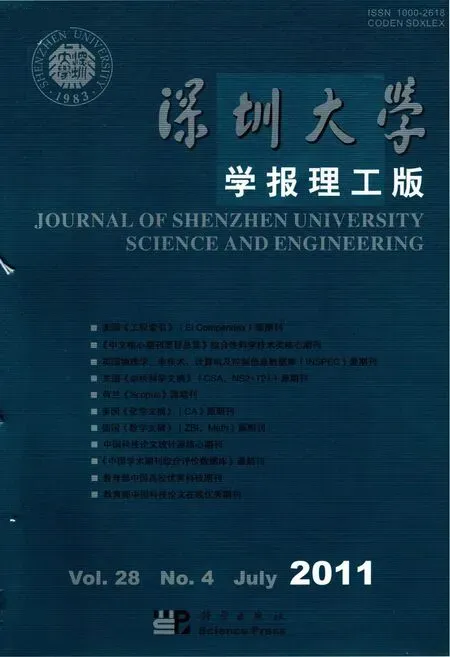
The X-ray tube we designed is comprised of an electron emitter,a cathode cup,a structured anode(target),and a glass envelop.The so called structured anode includes a structured target,an anode cap,and an anode,see the Fig 1.The structured target is enchased on the surface of the anode,whose partial enlargement is sketched on the left of the figure.In fact,it is a group of periodic parallel grooves formed by repeating stacking alternating high Z(atomic number)material strip and low Z strip.The high Z material constitutes the walls of the grooves,and the low Z material the bottoms of grooves.The top surface of the wall is a slope at an angle of 6°from horizontal,normal of which is pointed to the output window.The bottom of a groove is also a slope with an angle of 45°from wall and its normal is pointed to the opposite direction to the output window.The depth of groove is 0.7 mm.The thickness of wall plus the width of groove form one period of groove array,and these values are relative to the parameters of GXPI system and the target angle.For example,if the imaging system requires a 40 μm period and 10 μm coherence,for a 32°target angle the period is 64 μm and the wall thickness 16 μm;while for a 6°target angle the two values are 380 μm and 95 μm,respectively.In the two cases the optical focal spots are the same,a group of parallel line fringes,reference to the Fig 2.The only difference between them lies in the electronic focal spot on the target.The smaller the target angle is,the higher the radiation flux.From the viewpoint of practical application in medical diagnosis and considering the technological level,the X-ray target of angle 6°is thought to suit for such the new X-ray tube.
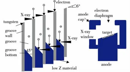
Fig.1 Diagram of structured tungsten target.The right is a sketch of anode,and the left is the drawing of partial enlargement of the structured target.图1 结构钨靶示意图.右为阳极结构图,左为结构靶放大图.
Fig.2 Pattern focal spot of an array of parallel lines.图2 阵列平行线焦斑示意图
The physical principle behind the structured anode is that the fate of X-rays emitting from the top surface of the groove walls is completely different from that of X-rays emitting from the groove bottom,which gives the fringe pattern to the focal spot.When the energetic electrons come to the target and impinge the top surface,the radiated X-rays are the same as the ones of conventional tubes.However, once the energetic electrons come into the groove and impinge the bottom,the X-rays radiate to the opposite direction to the output window of tube owing to the inclined direction of bottom surface.During the propagation of the X-rays in the opposite direction they will meet the groove walls and partial base of anode,and will be attenuated by absorption or scattering,with their fading away.So the X-rays emitted from groove bottoms have no contribution to the X-ray output,and the emitting X-rays from the output window of tube come only from the top surface of groove walls,reference to Fig 1.Owing to the periodicity of walls,the optical focal spot has also a periodic pattern,that is,a focal spot of parallel lines.X-rays from each lines has some spatial coherence,while the number of line lends the increase of flux.So we can say that the X-ray tube of parallel focal lines can generate X-rays of high radiation flux and of high spatial coherence.
In this tube,a sharp fringe pattern may be hoped to obtain if only the electrons that hit the top surface of groove walls generate X-rays.But in fact,there is some possibility for electrons to hit the walls of groove,deteriorating the fringe contrast of optical focal spot.In the conventional axis-symmetry field tube,electrons move along a curve path owing to the focusing of electric field.When they come to the target,there is some possibility for their impinging to the walls.But electrons can move along the straight paths under the application of a planar-symmetric electric field,with little chance for their coming to the walls,see Fig 3.So we designed a cathode structure of planar-symmetry for increasing the contrast of fringe pattern by reducing the chance of electrons to hit the walls of grooves.In our X-ray tube,a helical coil filament is positioned in the slit within the cathode cup.In general the filament is tangent to the bottom of the cathode cup,and the adjustment of the filament position will change the shape size of focal spot.The separation of the filament and the top plane of anode cap is designed as 15 mm and the filament is perpendicular to the grooves in the target.Figure 4 gives the results of electric potential distribution within the X-ray tube with planarsymmetry fields.Figure 5 is the photograph of the tube we designed and enveloped by taking the above factors into account.For its safe operation we enclosed the tube in a protective casing which was filled with oil.The tube casing performs the following main functions:high voltage insulation, cooling, protection against implosion,protection against radiation.

Fig.3 Trajectories of electrons in axis-symmetry and in planar-symmetry fields.图3 轴对称及平面对称场的电子轨迹
2 Measurement of focal spot

Fig.4 Electric potential distribution in the planar-symmetry field X-ray tube.图4 平面对称场X射线管的电势分布

Fig.5 The photograph of the new designed X-ray tube of structured target and with planar-symmetry field.图5 新设计的结构靶平面对称X射线管
For measuring the focal spot of the X-ray tube,a pinhole of 10 μm diameter was inserted close to the side window.Seeing from the side window,the period of parallel line array focuses was designed 40 μm with the width of line focus 10 μm.A magnification was necessary.In our experimental setup,a high resolution film was a 1.4 m distant from the pinhole,while the separation of the pinhole and the center of the target was 8.75 cm,which giving a 16°magnification of the focal spot.Under the application of a 50 kVp(Vp stands for the peak voltage)voltage and 2 mA current to the tube,the net exposure time was set to 4 h.Figure 6 is the photograph of the experimental result taken by scanning the film.From the photograph,the focal spot profile was measured as about 0.8 × 0.8 mm2and an array of parallel lines could be seen clearly.What needs to supply is that some contrast of the focal spot in the final photo may be lost owing to the transfer of the image.
3 Experimental results

Fig.6 The photograph of the focal spot with an array of parallel lines.图6 平行线阵列X射线焦斑的实测照片
Using the X-ray tube we designed and fabricated as the X-ray source,a grating-based imaging system was constructed in our laboratory,in which an X-ray phase grating and a detector with the function of amplitude grating were included with reference to the figure 7.According to the experimental conditions in our laboratory and the structured parameters of the X-ray tube above mentioned,we designed a phase grating with period of 5.6 μm and depth of 60 μm suitable for hard X-rays[8].The detector we designed and fabricated in this system had the function of amplitude grating,in addition to the function as a high resolution detector[9],because it has the same pattern as amplitude grating of 3.0 μm period.The fluorescent materials of the screen was CsI(Tl),being filled into holes of about 150 μm depth fabricated in the Si substrate.The diameters of the phase grating and the scintillation screen are all the same,5 inches.The distance of the phase grating to the axis of X-ray tube was set to 2.4 m,and that to the scintillation screen of detector was 108.5 mm.The screen was coupled directly to a cooled CCD camera(PI Corp.),its effective pitch of pixels was 30 μm ×30 μm owing to the 1.5 × magnification of optical fiber taper.

Fig.7 The system configuration of grating-based X-ray phase contrast imaging using the X-ray tube of structured target.图7 利用线发射体阵列X射线源的组成的光栅微分干涉成像系统组成示意图
The tube voltage was 70 kVp,and its anode DC current was 2 mA.Figure 8 shows images obtained from the above system with a fresh chicken wing placed in front of the phase grating.The left image is the one of the moiré images by phase shifting method,that is,the conventional absorption image practically.We took 5 steps to complete an image acquisition and 10 images per step were taken and then averaged as the image in a given step for phase retrieval.The exposure time per image was 10 s.The right image is the differential interference image obtained by the 5-step phase-shifting method[4].From the comparison,we can see that only the bone projection shadow can be found in the absorption image,however the detail structures in the bone and muscle are clear.The most X-rays under the voltage of 70 kVp transmitted the chicken wing,the poor absorption contrast was formed in the image.But the phase differences of the transmitted X-rays were large relatively,so the clear phase image of the same wing displayed in the phase image.

Fig.8 The phase image of a chicken wing obtained using the designed X-ray tube.Left:absorption image;right:the differential interference image from 5-step phase shifting methods.图8 利用研制的X射线源作为光源,得到的鸡翅的相衬图像照片.左侧是鸡翅的吸收图像;右侧是利用5步相移法得到的微分干涉图像.
Conclusions
In conclusion,the X-ray tube of structured target can be used for grating-based X-ray phase contrast imaging.Owing to the active emission of X-rays in this tube,more X-rays from the target can be used for imaging,more close to practical applications.This work is just the initial and better results may be seen by the optimal computation and design of X-raytube.
† This work was supported by the National Nature Science Foundation of China(11074172)and the Key Important Project of the Basic Research Program of Shenzhen(JC200903130326A).
[1] David C,Nohammer B,Solak H H,et al.Differential X-ray phase contrast imaging using a shearing interferometer[J].Applied Physics Letters,2002,81(17):3287-3289.
[2] Momose A.Demonstration of X-ray talbot interferometry[J].Japanese Journal of Applied Physics,2003,42(7B):L866-L868.
[3] Weitkamp T,Diaz A,David C,et al.X-ray phase imaging with a grating interferometer [J].Optics Express,2005,12(16):6296-6304.
[4] Pfeiffer F,Weitkamp T,Bunk O,et al.Phase retrieval and differential phase-contrast imaging with low-brilliance X-ray sources[J].Nature Physics,2006,2(4):258-261.
[5] NIU Han-ben,GUO Jin-chuan,WANG Kai-ge,et al.A new kind of X-ray tube and its production method:China,200610062487.1 [P].2007-02-17.(in Chinese)
[6] Momose A,Yashiro W,Kuwabara H,et al.Gratingbased X-ray phase imaging using multiline X-ray source[J].Japanese Journal of Applied Physics,2009,48(7):076512-1-076512-5.
[7] Coolidge W D,A powerful roentgen ray tube with a pure electron discharge [J].Physical Review,1913,2(6):409-430.
[8] LIU Xin,LEI Yao-hu,ZHAO Zhi-gang,et al.Design and fabrication of hard X-ray phase grating[J].Acta Physica Sinica,2010,59(10):6931-6936.(in Chinese)
[9] LIU Xin,GUO Jin-chuan,NIU Han-ben.A new method of detecting interferogram in differential phase-contrast imaging system based on special structured X-ray scintillator screen [J].Chinese Physics B,2010,19(7):070701-1-070701-6.
参考文献:
[1]David C,Nohammer B,Solak H H,等.利用剪切干涉仪的微分X射线相衬成像 [J].应用物理快报,2002,81(17):3287-3289.(英文版)
[2]Momose A.X射线泰伯干涉仪的演示 [J].日本应用物理杂志,2003,42(7B):L866-L868.(英文版)
[3]Weitkamp T,Diaz A,David C,等.光栅X射线相位成像干涉仪 [J].光学快讯,2005,12(16):6296-6304.(英文版)
[4]Pfeiffer F,Weitkamp T,Bunk O,等.低亮度X射线源的微分相衬成像及其相位恢复 [J].自然物理,2006,2(4):258-261.(英文版)
[5]牛憨笨,郭金川,王凯歌,等.一种新型X射线管及其制作方法:中国,200610062487.1 [P].2007-02-17.
[6]Momose A,Yashiro W,Kuwabara H,等.利用多线源的基于光栅的X射线相衬成像 [J].日本应用物理杂志,2009,48(7):076512-1-076512-5.(英文版)
[7]Coolidge W D.纯电子放电的功率伦琴射线管 [J].物理评论,1913,2(6):409-430.(英文版)
[8]刘 鑫,雷耀虎,赵志刚,等.硬X射线相位光栅的设计与研制 [J].物理学报,2010,59(10):6931-6936.
[9]刘 鑫,郭金川,牛憨笨.基于特殊结构X射线闪烁屏的微分干涉成像系统中探测干涉图样的新方法 [J].中国物理 B,2010,19(7):070701-1-070701-6.(英文版)
2011-05-31
国家自然科学基金资助项目 (11074172);深圳市科技计划基础研究重点资助项目 (JC200903130326A)
郭金川 (1964-),男 (汉族),河南省浚县人,深圳大学副研究员、博士.E-mail:jcguo@szu.edu.cn
高辐射通量空间相干X射线管
郭金川,周 彬,刘 鑫,任席奎,牛憨笨
深圳大学光电子学研究所,光电子器件与系统教育部重点实验室,广东省光电子器件与系统重点实验室,深圳 518060
针对光栅X射线相位衬度成像技术中如何获取高辐射通量和高空间相干的台式X射线源的问题,研制一种桌面X射线源.与传统X射线源不同,其阳极采用平行深沟道阵列的结构靶,灯丝发出的电子经加速聚焦后作用于结构靶,产生高辐射通量的一维相干X射线,其焦斑呈平行线阵列结构分布.将这种X射线管用于基于光栅的X射线相衬成像系统的光源,利用5步相移法得到了新鲜鸡翅的X射线相衬图像照片.
X射线产生;X射线管;结构阳极;焦斑;相干性;电子束
O 434.11;TN 14
A
1000-2618(2011)04-0315-CA
O 434.11;TN 14
A
Abstract:1000-2618(2011)04-0311-05
book=315,ebook=45
【中文责编:方 圆;英文责编:卫 栋】
猜你喜欢
戏曲研究(2022年1期)2022-08-26
小学生优秀作文(低年级)(2021年10期)2021-11-24
学生导报·东方少年(2021年19期)2021-06-28
大理文化(2020年12期)2021-01-23
The Crop Journal(2019年6期)2019-12-20
文苑(2019年14期)2019-08-09
小学生作文辅导(2018年3期)2018-11-28
现代营销(创富信息版)(2018年7期)2018-09-05
快乐语文(2017年18期)2017-08-11
烟草科技(2015年8期)2015-12-20