
Time-resolved ultra-small-angle X-ray scattering beamline (BL10U1)at SSRF
2024-04-25 07:15WenQiangHuaChunMingYangPingZhouFengTianJinYouLinYuZhuWangXiaoYunLiXiaRanMiaoChunXiaHongQiuShiHuangXinTongZhaoYongFengMenJieWangXingYuGaoXiuHongLi
Nuclear Science and Techniques 2024年2期
Wen-Qiang Hua · Chun-Ming Yang · Ping Zhou · Feng Tian · Jin-You Lin · Yu-Zhu Wang · Xiao-Yun Li ·Xia-Ran Miao · Chun-Xia Hong · Qiu-Shi Huang · Xin-Tong Zhao · Yong-Feng Men · Jie Wang · Xing-Yu Gao ·Xiu-Hong Li
Abstract The construction of a new beamline, BL10U1, was completed at the Shanghai synchrotron radiation facility in 2020.This multipurpose beamline was designed to provide X-ray scattering techniques such as ultra-small-angle X-ray scattering(USAXS), small-angle X-ray scattering (SAXS), wide-angle X-ray scattering, and microfocus SAXS (μSAXS) for a broad user community.To realize fast time-resolved USAXS experiments, the beamline adopted an in-vacuum undulator with a total length of 1.6 m as the photon source.An in-house cryogenic-cooled double multilayer monochromator was installed to deliver a photon flux of approximately 1013 photons/s at a photon energy of 10 keV.The three-year successful operation of this beamline demonstrated that the monochromator operated smoothly, as expected.BL10U1 has three end stations in succession: USAXS end station, μSAXS end station, and end station for industrial applications.The minimum scattering vector q ~ 0.0042 nm-1 at 10 keV can be achieved at the USAXS end station equipped with a 28 m-long and 1.8 m-diameter vacuum flight tube.At the μSAXS end station, a beam spot of less than 10 × 8 μm was achieved for micro-SAXS experiments.In contrast, in situ experimental instruments up to 5 m high and 8 m wide can be mounted at the industrial application end station, which offers industrial scientists the opportunity to use their large industrial equipment.BL10U1 opens up a new capability to investigate phenomena such as non-equilibrium and dynamic processes of materials with a wide length scale from angstroms to micrometers with millisecond time resolution.In this paper, we also report beamline design considerations and commissioning results.
Keywords Synchrotron radiation · Ultra-small-angle X-ray scattering · Micro small-angle X-ray scattering · USAXS · Time resolved · μSAXS
1 Introduction
With the development of third-generation and diffractionlimited synchrotron facilities over the past few decades,highly brilliant small-angle X-ray scattering (SAXS) and wide-angle X-ray scattering (WAXS) methods have been extensively employed in soft matter and materials science for structural elucidation [1—4].SAXS/WAXS techniques can detect nanostructures over a size range spanning from several angstroms to hundreds of nanometers in reciprocal space [5, 6].The time resolution was also reduced to the millisecond range using a high-flux X-ray beam and a fast high-dynamic noise-free detector.This advancement enables the exploration of various key scientific and technological issues using time-resolved SAXS/WAXS beamlines and related equipment incorporating thermophysical, rheological, and biophysical techniques [7—9].
To detect the scattering information at a smaller angle,ultra-small-angle X-ray scattering (USAXS) has proven to be a powerful technique for the structural analysis over a size range from a hundred nanometers to several micrometers[10, 11].Traditionally, USAXS and SAXS/WAXS experiments have been performed on separate instruments or different ways of acquiring signals, such as the Bonse—Hart multi-crystal instrument.However, the synchrotron USAXS instrument, which employs a long vacuum pipe combined with fast area detectors, has multiple advantages, providing high angular and time resolutions for in situ investigations of highly oriented specimens and time-dependent processes.Furthermore, it can be simply and logically combined with normal SAXS/WAXS instruments to obtain a more powerful technique with a wider detectable scattering angle.
In recent years, owing to the characteristics of their longchain structure, polymers have exhibited physical properties that vary widely across different space and time scales.Thus,effective and real-time monitoring of the structural evolution in the range of nanometers to micrometers is a key problem that must be urgently addressed in structural design, preparation, and processing.USAXS/SAXS/WAXS (USWAXS)synchronous measurements can realize uniform real-time observation of the molecular chain motion of polymer materials, as well as the morphological evolution and rheological behavior of aggregates, in different space and time scales.
This article presents the main technical specifications of the new BL10U1 beamline at the Shanghai Synchrotron Radiation Facility (SSRF), which required three years for its design and construction.The beamline completed acceptance testing at the end of 2020, trial operations in 2021, and has been officially opened since 2022.The primary motivation for this beamline project, named time-resolved USAXS, was to expand the applicability of SAXS to relatively unexplored non-equilibrium processes of fundamental and practical interest, such as the internal multilevel structural evolution process of materials in the field environment (for example, plastics, rubber, and composites), the mechanism of structural evolution in the industrial processing of polymers and fibrous materials, the self-assembly of soft matter, and structural changes in the process of non-equilibrium dynamics.Combining USWAXS with a broadqrange (0.0042 nm-1<q< 40 nm-1) in the same setup greatly enhances the structural exploitation in such complex systems.
BL10U1 has three experimental stations: USAXS, microfocus SAXS (μSAXS), and industrial application stations,which are arranged in series and run in time-sharing mode.The USAXS experimental station involves a pinhole twodimensional USAXS measurement because the high angular resolution and two-dimensional diffraction patterns have special advantages in detecting signals from anisotropic samples and in time-resolved research.Spatially resolved SAXS is performed at the second station, where the specimen is scanned using a microfocus X-ray beam.μSAXS is a valuable tool for mapping the ultrastructural features of macroscopic samples [12].At the end of the beamline, the industrial application station is equipped with a large house for online SWAXS testing with large industrial equipment,thus offering a favorable platform for basic research and industrial applications.
Access to the USAXS beamline is provided through either the SSRF beam time application system (http:// ssrf.sinap.ac.cn/ propo sals/) or a rolling application system that accepts proposals at any time.To date, feedback from users has been positive and the number of experimental proposals at BL10U1 is increasing, showing that the USWAXS and μSAXS facility is already providing reasonable results.
2 Beamline
To satisfy the demanding specifications of the beamline,including the maximum photon flux, minimumqvalue, and microfocus spot size, the beamline scheme was meticulously designed through numerous ray-tracing simulations.
2.1 Beamline layout
The USAXS beamline layout is shown in Fig.1.A watercooled four-knife precision slit is positioned 21 m from the light source, limiting the acceptance angle of the subsequent optical components to 60 μrad × 20 μrad (H×V).The USAXS and P2 beamlines are canted and share a long straight section.A pair of water-cooled plane mirrors, situated at 24 m and mounted pack-to-pack, achieved a 6.4 mrad deflection in the horizontal direction.This design not only creates more space for downstream experimental stations but also reduces the heat load on the downstream optical elements.At 35 m from the light source, a double multilayer monochromator (DMM) is employed to provide a high flux.To optimize focusing, a pair of mirrors reflecting in the horizontal and vertical plane was adopted.The dynamic bending horizontal and vertical focusing mirrors are located 41 and 44 m away from the light source, respectively.In addition,both focusing mirrors are coated with Rh on the surface to significantly suppress high-order harmonics.Four slits with single-crystal blades (gallium arsenide) are positioned at 38.7, 45.8, 53, and 59 m to collimate the X-ray beam and obtain a low background.The high vacuum optical section and low vacuum experimental section are separated by an atmospheric pressure resistance beryllium window located at 67 m.From 70 to 128 m, three experimental stations are arranged in sequence: the USAXS, μSAXS, and industrial application stations.
2.2 Light source
To meet the demand for fast time-resolved USAXS experiments, the beamline adopted an in-vacuum undulator(IVU20) with a total magnetic length of 1.6 m [13].Only the central radiation cone of the undulator is used.With the 3.5 GeV electron beam energy of the SSRF and 300 mA beam current, the 1.6 m undulator generates a highly brilliant X-ray beam in the energy range of 8—15 keV.The root-mean-square (RMS) beam size and divergence were 168 μm × 34 μrad in the horizontal direction and 12 μm × 4 μrad in the vertical direction.The X-ray source features of the IVU20 of the USAXS were simulated at 10 keV using a third-harmonic wave (K= 1.22) for optimized performance.The main characteristics of the USAXS photon sources are listed in Table 1.
2.3 Double multilayer monochromator
To maximize the photon flux, the beamline utilizes a DMM (Fig.2a).Compared with the conventional Si (111)single-crystal monochromator, it achieves a high flux at the expense of a broader bandwidth [14].The increased bandwidth transmitted by the DMM can introduce a smearing effect on the scattering patterns; however, this has been proven to be negligible [15, 16].

Table 1 Main characteristics of the USAXS photon source
The Pd/B4C multilayers were fabricated at Tongji University, China.Two identical multilayer stripes[optical area: 130 mm × 25 mm and 320 mm × 25 mm(length × width), respectively] were coated on the surface of two rectangular super-polished Si substrates [size:150 mm × 33 mm × 30 mm and 330 mm × 33 mm × 30 mm(length × width × height), respectively] with surface roughness of < 0.2 nm and slope error of < 0.33 μrad (tangential)and < 0.6 μrad (sagittal).Two multilayer silicon < 100 > mirrors were covered with 150 alternating layers of Pd and B4C[17].The multilayer is designed with a period of 2.5 nm and gamma ratio ofΓ~ 0.5 (thickness of the Pd layer to the period) for the target working energy range of 8—15 keV.To achieve a saturated reflectivity, a multilayer with 150 bilayers was fabricated.The calculated bandwidth of the output X-ray beam from one multilayer is approximately 1.2% with the input beam’s divergence set at 20 μrad.

Fig.2 (Color online) double multilayer monochromator.a Inside view of the double multilayer monochromator vessel.b GIXR curves of two Pd/B4C multilayers at different energy levels
After deposition, the multilayers were characterized by grazing incidence X-ray reflectometry (GIXR) at the Cu-Kα emission line (Energy = 8.048 keV) with an angular resolution of ~ 0.008°, as shown in Fig.2b.The measured peak reflectances of the two multilayers were 61% at 8 keV.In the final acceptance test upon arrival at the SSRF, hard X-ray(Energy = 10 and 15 keV) GIXR curves were measured at SSRF-BL09B with an angular resolution of 0.01° [18].The measured peak reflectance of the GIXR curves were 65—66%@ 10 keV and 78—79% @ 15 keV with a 0.01° beam divergence, as listed in Table 2, and the energy resolution of the output beam was approximately 1.3—1.5% in the energy range.
The mechanical design of the USAXS DMM is similar to that of a channel-cut monochromator [16, 19], as depicted in Fig.2a.Only two shafts could be electrically adjusted to obtain a stable output beam with an uncertainty of direction < 0.3 μrad/2 h.The Bragg angle of the entire DMM system is used to change the energy, from 1.776° @ 8 keV to 0.946° @ 15 keV.The fine pitch angle of the second mirror is used to maintain the direction of the output X-ray beam.When the energy changes, the X-ray beam deflected from the first mirror travels along the meridian of the second mirror.The height offset of the output beam changes only 5.3 μm through the energy range, which is negligible for the entire beamline.The relationship between the X-ray energy and Bragg angle of this DMM was calibrated using theKabsorption edge of Cu @ 8.98 keV.The energy range was verified with theKabsorption edge of Co @ 7.71 keV and the L2 absorption edge of Pb @ 15.2 keV.
The peak absorption power density of the first multilayer film is 0.675 W/mm2.Based on the thermal analysis,indirect liquid nitrogen cooling was implemented to satisfy the requirements of the first multilayer slop error.The second multilayer also required an indirect cryogenic cooling method to improve the stability of the DMM system, which was achieved via a heat-conduction copper braid connected with the first mirror cryogenic-cooling system.After six months of examination and three years of operation, the DMM system worked well, and no performance degradation was found owing to the low-temperature environment [20].
2.4 Focusing mirrors and focus beam properties
Generally, the X-ray beam is focused on the detector to mitigate instrumental smearing in SAXS experiments.Similarly,in our case, as depicted in Fig.3, three types of beamline layouts were designed for each experimental station to obtain optimized experimental results.At the USAXS station, the horizontal and vertical focusing mirrors separately focus onto the USAXS detector plane with a beam size of 379 μm × 341 μm.A similar optical layout is applied to theindustrial application station, where the horizontal and vertical focusing mirrors focus into a 525 μm × 491 μm beam spot on the detector plane, 128 m away from the light source.
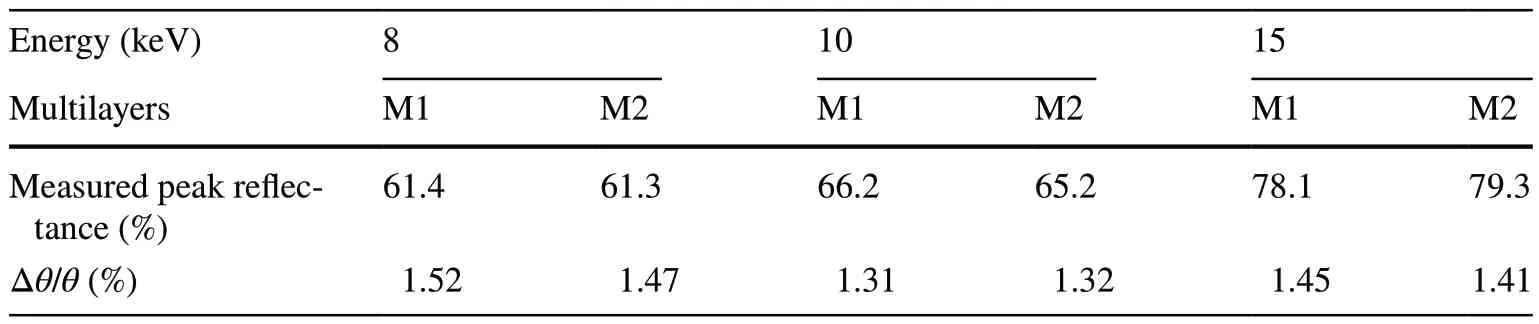
Table 2 Optical performance of the GIXR curves of the two Pd/B4C multilayers

Fig.3 (Color online) optical layout designed for the three experimental stations (side view)
At the μSAXS station, a secondary focus mode was adopted to achieve a micron-sized beam spot.As illustrated in Fig.3, the secondary focusing beam spot is located 69.5 m away from the light source, where a high-stability slit is employed to control the beam size.The secondary beam spot size is a 189 μm × 175 μm quasi-Gaussian spot,as shown in Fig.4a.To maintain the flux and facilitate the change in energy, a pair of KB focusing mirrors (100 and 100.5 m away from the light source, respectively) was used to focus the spot onto the microfocus sample (101.5 m away from the light source).The KB mirror system was provided by CINEL, and the mirrors and bender mechanics were manufactured by Thales SESO.The mirrors were mounted inside an ultrahigh-vacuum chamber with adjustable support structures and a highly stable granite.A horizontal focusing mirror was placed upstream of the vertical focusing mirror to reduce smearing of the SAXS data.The surface shapes of the mirrors were planar, and the mirrors were bent into elliptical cylinders with bending mechanisms according to the focusing parameters.The bender mechanics is composed of a classical U-bender mechanics (Thales SESO patent) equipped with an additional actuator, introducing a small correction to the profile obtained at each radius of curvature and correcting the polynomial profiles up to the 3rd order.The bender system allows the realization of pure elliptical bending owing to the combination of two effects:(1) 2-actuator mechanics and (2) a mirror profiled with a variable width (variable inertia), allowing the correction of higher-order aberrations.The attitude of the mirrors, encompassing both 3D positions and Euler angles (pitch, roll, and yaw), can be remotely adjusted for pitch and roll rotations,strip changes, beam direction, and normal translations, and all axes are independently adjusted for high stability.
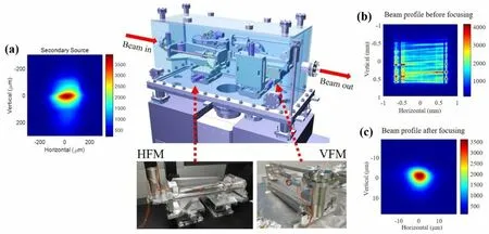
Fig.4 (Color online) display of the KB mirrors, chamber, and X-ray beam focusing process for the μSAXS experiment: a Beam profile of the secondary source focused by the horizontal and vertical focusing mirrors.Beam profile at the μSAXS sample plane (b) before and c after focusing by the KB mirror systems
The X-ray beam focusing process for the μSAXS experiment is displayed in Fig.4b, c.Prior to bending the mirrors, noticeable streaks appeared in the reflected beam,which resulted from slope errors in the mirror profiles.Through the bending process and attitude adjustment of the mirrors, the minimum focusing beam spot size can reach 7.6 μm × 4.3 μm, representing a convolution effect of the compression ratio of focusing and the mirrors’ slop error.
Given that the total USAXS beamline length is approximately 128 m, a slight angular deviation in the components of the light source or beamline can cause significant fluctuations in the focused beam spot position and photon flux.This seriously affects the results of the USAXS or μSAXS experiments.Hence, beam spot stability is crucial for the USAXS beamline.To ensure beam spot stability, the drift of the beam position in a typical experiment should be less than 10% of the focusing beam spot.Therefore, it is necessary to monitor the changes and vibrations in the beam spot positions, flux, and size on an exposure timescale.An online monitoring device consisting of a Ce: YAG scintillator,zoom lens, and camera was used for real-time monitoring of the X-ray beam at 1, 10, and 100 Hz.The X-ray focusing process was observed dynamically and adjusted in realtime using mirrors and other optical elements, as shown in Fig.4.After the system was tested in the top-up mode at the SSRF, the root mean square (RMS) values of the deviation of the normalized beam flux as well as horizontal/vertical beam spot position and width at the μSAXS experimental station were obtained and are listed in Table 3.All the RMS values of the measured deviation were lower than 5% of the design value and met the experimental requirements very well.Beamline stability can be influenced by many factors,including the radiation source itself and the behavior of the X-ray optics under the thermal load of the white X-ray beam.However, as can be observed in Table 3, the jitter amplitude of the focal spot in the horizontal direction was greater than that in the vertical direction, which is supposed to be caused by the combined effect of slight shaking of the X-ray source and the flow vibration of the water-cooling system of the horizontal deflector in the white-light region.This problem can be mitigated by replacing the gravitational water cooling unit.
3 End-stations
The overall layout of the three stations is shown in Fig.5.The USAXS beamline, categorized as one of the three“super-long beamlines” at the SSRF, was designed to achieve a wideqrange and provide sufficient space for industrial application experiments.Based on calculations from SHADOW ray tracing, the beamline must be 128 m-long and extend outside the main building of the SSRF into its dedicated satellite building.The majority of USAXS stations are situated in the main building of the SSRF, and only the USAXS detector is located in the satellite building.Both the μSAXS and industrial application stations are housed entirely in the satellite building, spanning a range of 96 to 128 m from the light source.
To maintain the stability of the experimental equipment,the satellite building was constructed with the same foundation as the main building.However, owing to the placement of the vertical focusing mirror 44 m away from the light source facing downward, the reflected beam had a downdip angle of 6.4 mrad.Consequently, the base height of the satellite building is 0.7 m lower than that of the main building.All three experimental stations were equipped with long vacuum tubes to minimize air absorption and parasitic stray light.
3.1 USAXS station
At the USAXS end station, time-resolved USAXS/SAXS/WAXS technology was developed, which can cover structural scales from Ångström to micrometers and track non-equilibrium dynamic processes.Duringpolymer processing, it is very important to clarify the structure—property relationship and control the stability of the polymer, which requires improvement of the time resolution of USWAXS techniques to the millisecond level.Real-time detection and tracking of multiscale structures in the process of structural formation and evolution of materials, and finally construction of the microstructure—property relationship at all scales can provide a direct basis for the optimization of material performance.A tridetector system is required for synchronous USWAXS acquisition.The USAXS camera system mainly consists of a 28.5 m-long vacuum pipe, three detectors, a moving rail,a Kohzu five-axis sample stage, and a beamstop system.Before the sample position, there are two scatterless slits,which are installed to eliminate stray light and parasitic scattering.The ion chamber and shutter are located at the exit of the beryllium window, 69 m away from the light source, and are shared by the three end stations.As shown in Figs.5 and 6, the USAXS vacuum flight tube, which has a length of 28.5 m and diameters of 1.8 m (for the foremost 7 m) and 0.5 m (for the backmost 21.5 m), was made of 8 mm thick stainless steel (Htc vacuum).For the tridetector system, the WAXS detector was mounted outside the USAXS flight tube around the entrance cone, and attitude adjustment was performed using a multi-axis movement system.The SAXS detector was placed in a vacuum tube and mounted on a motorized wagon traveling along a rail system.For SAXS measurements, this arrangement enables the automated adjustment of the sample-to-detector distance between 1 and 6.5 m in a precise and reproducible manner.The wagon assembly comprises an SAXS detector, a carriage, and a translation table that permits further repositioning of the detector in two dimensions perpendicular to the X-ray beam.At the end of the USAXS flight pipeline, a USAXS detector was placed in the air, and a two-axis translation stage was used to adjust it.To record the USAXS patterns, two 3 mm diameter beamstops and a 6 mm diameter beamstop were mounted in a vacuum to prevent the primary beam from hitting the SAXS and USAXS detectors.Because the scattering background is usually subtracted from that of the sample, the beam flux and transmission must be measured during SAXS and USAXS data collection.Therefore, a photoelectric element was integrated into the beamstop to measure the transmitted beam flux during sample exposure.Furthermore, an electric shield door was installed and integrated in front of the USAXS detector to prevent vacuum explosions and abnormal contact.The samples were then exposed to air.Both the upstream and downstream vacuums were isolated by thin high-quality mica windows ~ 20 mm thick and 10 mm in diameter.The X-ray-transparent window,made of fibrous carbon sheet with a thickness of approximately 400 μm and a diameter of 500 mm, was also glued and bolted onto the back flange of the three tubes.When conducting the downstream experiments, the upstream air section was replaced by vacuum pipes and flanges to minimize parasitic scattering introduced by the air and windows.The 23 m3tube volume was evacuated to 10—2mbar(1 Pa) in less than 0.5 h by an industrial dry screw pump(Edwards GX450).Subsequently, through the combined use of a high-vacuum dry pump (Edwards EPX500LE),vacuum gauge, and gas flow controller (MKS GE50A), the vacuum degree could always be maintained at 10—2mbar,which protected the in-vacuum detector from discharge and was conducive to the stability of the experimental state and consistency of the scattering data.The temperature of the in-vacuum detector was regulated to 298 K by circulating cooling water through a feedthrough flange into a vacuum.

Table 3 Root mean square (RMS) values of the deviation of the normalized beam flux and horizontal/vertical beam spot position and width at the secondary source (SS) and focus plane of the μSAXS experimental station (at different sampling frame rates: 1, 10, and 100 frames per second)
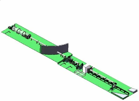
Fig.5 (Color online) overall layout diagram of the three end stations at BL10U1

Fig.6 (Color online) USAXS flight tubes: a, b Overall exterior and internal structure of the 1.8 m diameter vacuum pipe.c Section of the vacuum pipe between the main building and the satellite building
To demonstrate the capability of millisecond time resolution at the USAXS end station, time-resolved USAXS experiments on polystyrene microparticles were conducted,as illustrated in Fig.7.Polystyrene microparticles with a uniform diameter of 500 nm (shown in the inset of Fig.7b)served as a standard sample to illustrate the millisecondtime resolution and achievable minimumqvalue.Operating at a frame rate of 750 Hz, a series of USAXS patterns exhibited millisecond-time resolution capability by rapidly moving the sample position (Fig.7a).Operating at a frame rate of 750 Hz, a sequence of USAXS patterns demonstrated millisecond time-resolution capability, which was achieved by swiftly moving the sample from outside the X-ray beam spot to inside it, allowing for the observation of noticeable changes in the SAXS patterns (Fig.7a).Figure 7b presents the one-dimensionalI(q) curve obtained by integrating the 2D USAXS pattern.The red mark indicates the effective minimumqvalue that can be detected, which is 0.003 nm-1,corresponding to an available spatial scale of up to 2 µm.
3.2 μSAXS station
Fig.7 (Color online) time-resolved USAXS results of polystyrene(PS) microparticles at BL10U1.a USAXS patterns from nothing shows the time resolution of 1.33 ms by moving the sample position quickly and capturing images at a 750 Hz frame rate.b One dimensional I(q) curve from the integration of the 2D USAXS pattern;inset: SEM image of the PS nanoparticles

Fig.8 (Color online) a layout of the μSAXS experimental station (side view).b Detailed layout of the sample stage (top view).c Multi-axis motor table for the 3D translation and rotation/tilt of the sample.d I(q) curve and μSAXS pattern (inset) of the cowhells sample
SAXS technology is typically employed to study the phase transition or aggregation behavior of materials in local microstructures and microfluidic environments.The μSAXS experimental station was optimized to deliver a microfocused X-ray beam with a low divergence and a high photon flux at the sample position and allow for kinetic investigations in confined geometry with high time resolution [21].In Fig.8, the μSAXS camera system consisted of a 4 m-long vacuum pipe, μSAXS detector, online microscope camera,Kohzu multi-axis sample stages, and beamstop system.To ensure high stability during the long SAXS measurement time, both the sample stage and KB mirror system were placed on the same marble platform.Two scatterless slits were mounted on the front and back flanges of the KB mirror chamber to control the beam divergence and eliminate parasitic scattering.The multi-axis electric sliding table,combined with the online observation camera, facilitates attitude adjustment, scanning, and rotation operations of the sample and triggers the signal acquisition of the detector.The on-axis microscope camera consists of a camera with a wide dynamic range (Digital CMOS camera, C11440-36U,HAMAMATSU), variable magnification lens, reflecting mirror, Ce:YAG scintillator, and three-dimensional electric displacement tables.The camera points toward the lens and a mirror inclined at 45° and provides images of the sample in the direction of the X-ray beam without parallax error.The position and intensity profiles of the X-ray beam are displayed on a scintillator slice.As shown in Fig.8c, the sample is mounted on a computer-controlled multi-axis stage that can translate in two directions (x,y) in the plane of the detector and rotate around two axes corresponding to the rotation angleαand tile angleβ.The relative photon intensities of both the direct and transmitted beams were measured using the upstream ion chamber and a PIN photon diode embedded on the beamstop with a diameter of 6 mm.The X-ray transmittances of the samples were calculated based on these measurements.The μSAXS flight tube can be adjusted in length from 1 to 3.5 m and is mounted with a vacuum beamstop chamber at the end.
The μSAXS end station was designed to offer normal SAXS scanning, SAXS computed tomography, and novel SAXS tensor tomography techniques in many research areas such as polymer science, hybrid nanocomposite nanotechnology, and microfluidics [21—26].Cowhells, which have a lamellar structure with a period of 65 nm, served as standard samples to illustrate the available minimumqvalue [27].As shown in Fig.8d, a dimensional I(q) curve from the section integration of the 2D SAXS pattern was obtained at an exposure time of 1 s.The effective minimumqvalue that can be detected is 0.062 nm-1.The high contrast multi-order diffraction fringes highlight the high flux and low divergence capability of the μSAXS experimental station.
In μSAXS measurement, a scanning step of 10 μm is recommended, and a large beam size can be achieved by deliberately moving the sample position along the X-ray direction to a defocused state.In the near future, the μSAXS experimental station will undergo upgrades, including expanding the μSAXS/μWAXS combination to cover a widerqrange.Additionally, the plans involve introducing a fly scan mode or enhancing the efficiency of sample scanning and image acquisition.Further development of the SAXS data processing and 3D image analysis capabilities has been identified as a key focus for improvement.
3.3 Industrial application station
The industrial application station is located in a satellite building and dedicated to industrial application research using time-resolved SAXS/WAXS techniques.To meet the requirements of industrial applications, ample space (height:6 m, width: 8 m) is reserved for large-scale industrial equipment.The end station facilitates real-time detection of the nanostructural evolution of materials during industrial production [28].The SAXS/WAXS camera system mainly consists of a 21 m-long vacuum pipe, two detectors, and beamstop system.Scatterless slits are also used to control the beam size of the sample and reduce parasitic scattering.The two detectors are combined to collect scattering patterns on a millisecond timescale.The flight tube, with a length of 21 m and a diameter of 0.5 m, is made of 8 mm thick stainless steel.The WAXS detector is positioned outside the vacuum tube around the entrance cone; whereas, the SAXS detector operates in the air environment and is mounted at the end of the flight tube.A 3 mm diameter beamstop was mounted in vacuum to prevent the primary beam and to measure the transmitted beam flux with an embedded photoelectric element.Therefore, BL10U1 will contribute to thedevelopment of the national polymer industry and support industrial users in conducting frontier and practical research(Table 4).

Table 4 Main specifications of the three end stations of BL10U1(@10 keV @ 300 mA) at the SSRF
3.4 Main specifications of the three stations
The main specifications of the three experimental stations of BL10U1 at the SSRF are listed in Table 4.This beamline integrates various small-angle X-ray scattering techniques into a single instrument, enabling both static and kinetic investigations across scales ranging from angstroms to micrometers with a time resolution down to the millisecond range.The USAXS station achieves a minimum scattering vector ofq≤ 0.0042 nm-1at a wavelength of 0.124 nm.The industrial application station achieves a minimumq~ 0.0063 nm-1.The μSAXS station utilizes a focused beam spot of less than 10 µm, enabling spatial resolution SAXS experiments with millisecond time resolution and high throughput capability.
As shown in Figs.1 and 5, six detectors are required to satisfy the signal acquisition requirements of the three experimental stations, although some detectors can be shared.For weak scattering intensity, the detectors must have an optimal signal-to-noise ratio, sufficient sensitivity to provide singlephoton detectivity, and a high dynamic range.High frame rates and short readout times are essential for time-resolved experiments.In addition, the detectors should have a relatively large active area with an appropriate spatial resolution,preferably without gaps.However, it is impossible to meet all these specifications with the detectors currently on sale.Therefore, several detectors are used to obtain the required characteristics.
To meet the millisecond time-resolved experimental requirements, Dectris detectors were selected for the collection of the USAXS, SAXS, WAXS, and μSAXS scattering patterns.They provide a sufficiently large active area, high count rate, and high frame rate.To ensure the consistency of the experimental data and compatibility and software integration, five Dectris detectors (Table 5) were adopted at the three end stations.At the USAXS station, the L-shaped Pilatus3 × 900 K and L-shaped Pilatus3 × 2 M were used as the WAXS and SAXS (in-vacuum) detectors, respectively.The Eiger X 4 M was used as the USAXS detector for sufficient ultra-small-angle resolution over a wideqrange.At the μSAXS end station, the Eiger X 4 M was moved to the μSAXS camera system and used as a μSAXS detector.For industrial applications, the Eiger X 1 M and Pilatus3 X 2 M were designed to collect wide-angle and small-angle scattering patterns during simultaneous SAXS/WAXS experiments.
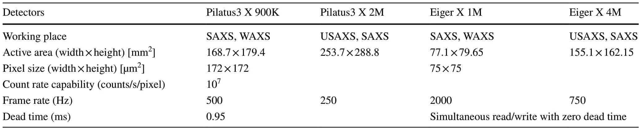
Table 5 Main specifications of the equipped detectors for the three experimental stations
4 Control and data-acquisition system
The beamline control and data acquisition software at the end stations and user interface are shown in Fig.9.The control and data acquisition system at the end stations consists of five main parts: the motor control system, data acquisition system, in situ device control system, synchronization control system, and data storage system.The motor control system includes a VME chassis, a CPU card (MVME5500),several controller cards (MAXv-8000-2), and two- and fivephase motor drivers, which are responsible for end station motor control.The data acquisition system primarily comprises detectors produced by Dectris.The synchronization control system uses a synchronization pulse generator to generate synchronization signals, sends them to the detector and shutter, and achieves synchronization control.The time delay of the pulse signal generated by the synchronous pulse generator is within nanoseconds.The data storage system provides the capability of storing massive amounts of data in the entire system.
The Standard Experimental Physics and Industrial Control System (EPICS) development software was employed to write the control program, facilitating communication within the entire equipment.This software can be completely adapted to the experimental needs using a userfriendly graphical user interface (GUI).This GUI displays several important beamline parameters such as the current of the SSRF and the beamline flux.Relevant parameters such as exposure time, image file name, and sample description can also be set in the GUI and transmitted to the Dectris detector operating program, which triggers data acquisition by opening the experimental shutter or moving the sample stages.The development of the GUI was based on CSSBOY (see http:// cs- studio.sourc eforge.net/ for more details).Users can perform millisecond time-resolved experiments at the USAXS experimental station.Special scanning and exposure schemes can be customized according to the actual needs of the user samples at the μSAXS experimental station.In industrial application end stations, special software integration and cable interfaces are reserved for in situ industrial equipment.

Fig.9 (Color online) diagram of the control and data acquisition system
For better performance, the detector data and metadata are independently saved on the disk array by the beamline servers and EPICS, respectively.ALBULA 3.0 (Dectris Co.Ltd, Baden-Daettwil, Switzerland) is used to display the recorded two-dimensional patterns.The Fit 2D software is available on the beamline for data display and manual data processing (https:// www.esrf.fr/ compu ting/ scien tific/ FIT2D/index.html) [29].
The potential and capability of the data acquisition system are demonstrated through the line-scans microfocus SAXS experiment at the μSAXS station, as shown schematically in Fig.10 on the online optical micrograph.In the case of polymer injection-molded samples, distinct scattering patterns indicate a typical skin layer and core layer structure [30].Additionally, the use of polarized optical microscopy images aids to illustrate the morphology of the samples, helping to delineate the skin and core regions.These results highlight the effectiveness of the data acquisition system in capturing detailed structural information.
5 Summary and prospect
The BL10U1 beamline at the SSRF was meticulously designed as a multipurpose, undulator-driven, combined USAXS, SAXS, WAXS, and SAXS technique to meet the needs of the broad user community.The beamline boasts the capacity for in situ, millisecond time-resolved, broadqrange investigations.The incorporation of a cryogeniccooled DMM is pivotal for achieving a high photon flux at the beamline.The USAXS beamline comprises three distinct stations tailored to address varied scientific research requirements: the USAXS, μSAXS, and industrial application stations.Notably, the SAXS and industrial application stations are situated in a satellite building.The USAXS station serves as a powerful platform for the nondestructive characterization of microstructures within samples,boasting state-of-the-art spatial resolutions ranging from micrometers to angstroms.At the μSAXS experimental station, meticulous optimization ensures the delivery of a microfocused X-ray beam with low divergence at the sample position, facilitating kinetic investigations into nanostructure distribution in the microregions of inhomogeneous samples.The industrial application station provides ample space to accommodate a variety of large industrial equipment and user-developed in situ sample environments.Since its official opening to users two years ago,the beamline has yielded numerous fruitful experimental results.As the beamline equipment and methodologies continue to evolve, coupled with the efficient utilization of high-performance experiments by users, it is expected that even more exciting and prolific results will emerge in the future.
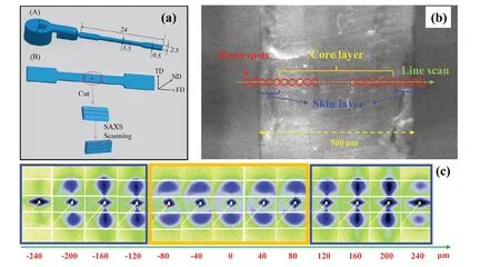
Fig.10 (Color online) a schematic representation of the ultrasonic injection-molded polypropylene sample [30]: (A) dimensions of the sample bar (unit: millimeter); (B) sample position used for SAXS scanning measurement.FD, TD, and ND represent the flow direction,transverse direction, and normal direction, respectively.The direction of the incident X-ray beam is parallel to the normal direction for SAXS measurement.b Online optical microscopic image of the scanning path on the sample.For SAXS mapping experiments, strips with a breadth of approximately 0.5 mm are cut from the middle of the specimens along the flow direction, and the X-ray beam spot (red circle) scans along the sample thickness direction with a 10 μm step size.c Selected SAXS images for display at intervals of 40 μm.The core layer (orange) and skin layer (blue) produce different SAXS patterns
AcknowledgementsWe thank the kind help from our colleagues at the SSRF (Wan-Qian Zhu, Song Xue, Pei-Rong Gong, Nan Wang,Jiong-Jun Lv, Dong Su, Feng-Gang Bian, Xiao-Long Li, Jian He,Zhong-Liang Li, Yan Zhao, Hong-Liang Qin, Hong-Xin Luo, Zeng-Yan Zhang, Ming Chen, Zhou-Xia Zhu, Hui-Chao Xu, Ying-Hua He,Yi-Fei Zhang, Ying-Feng Wu, Ping Liu, Zhao-Hong Zhang, and Yun Liu) for their technical support in the beamline construction.
Data availabilityThe data that support the findings of this study are openly available in Science Data Bank at https:// cstr.cn/ 31,253.11.scien cedb.15014 and https:// doi.org/ 10.57760/ scien cedb.15014.
Declarations
Conflict of interestThe authors declare that they have no competing interests.
 Nuclear Science and Techniques2024年2期
- Nuclear Science and Techniques的其它文章
- Measurement of the neutron-induced total cross sections of natPb from 0.3 eV to 20 MeV on the Back-n at CSNS
- Nuclear charge radius predictions by kernel ridge regression with odd-even effects
- Unbound 28 O, the heaviest oxygen isotope observed: a cutting-edge probe for testing nuclear models
- Development of CONTHAC-3D and hydrogen distribution analysis of HPR1000
- Total ionizing dose effect modeling method for CMOS digital-integrated circuit
- A fast forward computational method for nuclear measurement using volumetric detection constraints