
Development of a high-repetition-rate lumped-inductance kicker magnet prototype for the beam switchyard of SHINE
2024-04-25 07:15YongFangLiuRuiPingWangJinTongBoZhangSiChenQiBingYuanHaiXiaoDengMingGuBoLiu
Nuclear Science and Techniques 2024年2期
Yong-Fang Liu · Rui-Ping Wang · Jin Tong · Bo Zhang · Si Chen · Qi-Bing Yuan · Hai-Xiao Deng ·Ming Gu · Bo Liu
Abstract The Shanghai high-repetition-rate X-ray free-electron laser and extreme light facility (SHINE) operates at a maximum repetition rate of 1 MHz.Kicker magnets are key components that distribute electron bunches into three different undulator lines in a bunch-by-bunch mode.The kicker field width must be less than the time interval between bunches.A lumpedinductance kicker prototype was developed using a vacuum chamber with a single-turn coil.The full magnetic field strength was 0.005 T.This paper presents the requirements, design considerations, design parameters, magnetic field calculations, and measurements of the kicker magnets.The relevant experimental results are also presented.The pulse width of the magnetic field was approximately 600 ns, and the maximum operation repetition rate was 1 MHz.The developed kicker satisfies the requirements for the SHINE project.Finally, numerous recommendations for the future optimization of kicker magnets are provided.
Keywords X-ray free-electron laser · Kicker magnet · Beam switchyard · High repetition rate · Ni-Zn ferrites
1 Introduction
The X-ray free-electron laser (XFEL) facility based on an electron linear accelerator (LINAC) is regarded as a fourthgeneration light source with the characteristics of high intensity, exceptional brightness, ultrashort pulse duration, and spatial coherence [1].The high repetition rate of hard X-ray FELs is motivated by the scientific requirements of high average coherent X-ray power with ultrafast angstrom spatial resolution [2, 3].The Shanghai high-repetition-rate XFEL and extreme light facility (SHINE) based on a superconducting accelerator is the first hard XFEL in China [4].It is now under construction at Shanghai Tech University and the Shanghai Advanced Research Institute (SARI), Chinese Academy of Sciences.It can provide an electron beam with a repetition rate of up to 1 MHz and an energy of 8 GeV.To improve the utilization of high-repetition-rate beam bunches and satisfy the rising demand for user experiments, a beam switchyard is applied to distribute electron beam bunches to multiple undulator lines [5].
The beam distribution switchyard is located midway between the endpoint of the LINAC and the entrance of the undulator lines to distribute the electron beam bunches within a specified mode.A kicker-septum section is used to distribute the electron beam bunches to the three different undulator lines.Kicker magnets are key components for distributing electron beam bunches into different undulator beamlines.For a more flexible distribution throughout the three undulator lines, the kicker should be able to perform bunch-by-bunch kicks on the electron beam bunches and should also be programmable for arbitrary distribution patterns.Major XFEL facilities worldwide have designed beam switchyard systems.The beamline switchyard of the Spring-8 Angstrom Compact Free-Electron Laser (SACLA)uses a kicker and a direct-current twin-septum magnet to deflect electron beam bunches to different undulator lines[6].The kicker operates at a repetition rate of 60 Hz and a deflection angle of 0.5° [7].The SwissFEL beamline switchyard is composed of a high-Q-factor resonant kicker and a direct-current septum magnet [8].The resonant kicker separates the two bunches separated in time by 28 ns [9, 10].The beamline switchyard of the LCLS-II is composed of a transmission-line kicker and a Lambertson septum magnet to deflect 929 kHz of 4 GeV electron beam bunches into different undulator lines [11].This type of kicker is diffi-cult to use owing to its higher-order magnetic field [12].The beamline switchyard of the European XFEL is achieved using a combination of two types of kicker (flat-top kicker and burst kicker) and a Lambertson septum [13].A burst kicker with an operating frequency of 5 MHz kicks single bunches out of a train [14].These bunches are dumped, and the repetitive amplitude stability of the kicker is only 0.1%.A flat-top kicker with an operating frequency of 10 Hz and a repetitive amplitude stability of 0.03% kicks approximately 100 bunches into the undulator line [15].The Shanghai Soft XFEL (SXFEL) facility applies a single kicker magnet to separate 50 Hz electron beam bunches into two separate undulator lines [16].However, none of the existing kicker magnets satisfies the requirements of the 1 MHz bunch-bybunch kick capability for the SHINE project.
Therefore, a lumped-inductance-type kicker with a single-turn coil in a vacuum chamber was developed for a beam switchyard.This paper presents the physical requirements, design parameters, magnetic field calculations, and measurements of the lumped-inductance kicker.The design considerations for the choice of the iron core material, thermal analysis, and structural design are described.Simulation results showed that the magnetic field and thermal distribution satisfied these requirements.Theoretical analyses and program simulations were performed to verify the feasibility of the basic structure of the kicker.Finally, the relevant experimental results are presented.Thus, we developed a kicker magnet that satisfies the requirements for the SHINE project.
2 Physical requirement and kicker layout
There are three kicker-septum sections in the SHINE beam switchyard.Each undulator line uses a kicker-septum section to distribute the electron beam bunches.The kicker inductance is directly proportional to the kicker length.A large inductance will lead to the intractable challenge of a pulse waveform < 1 μs.Therefore, each kicker-septum section contained several kicker magnets.The three undulator lines have the same configuration as that of the kicker-septum section.Figure 1a shows a schematic of a one-section beamline switchyard composed of a kicker and septum magnets.K0—K9 denote the kicker.Each of the ten magnets can independently regulate both the delay time of the trigger and the strength of the magnetic flux density to guarantee that the electron beam bunches pass through the kicker at the flat top of the pulse waveform with the required deflection strength [17—19].Here,Qis the quadrupole magnet in the FODO lattice.S1 in Fig.1a means the septum magnet.The red and purple lines show the paths of the deflected and nondeflected electron beam bunches, respectively.The beam switchyard was based on the configuration of a vertical deflection kicker combined with a horizontal deflection direct-current septum.Ten kicker magnets followed by a direct-current septum separate the 1 MHz electron beam bunches and send them to three separate undulator lines with arbitrary distribution patterns.Five kicker magnets were installed before the quadrupole (Qin Fig.1a), and the other five kicker magnets were installed after the quadrupole.Each kicker provides a vertical deflection angle of 0.1 mrad, and hence, the ten kicker magnets provide a total deflection angle of 1 mrad.At the entrance of the septum magnet, the electron beam bunches are shifted by approximately 17 mm from the initial horizontal height.The septum is a Lambertson type and provides a horizontal deflection of 31 mrad [20, 21].When the kicker magnets are switched off, the electron beam bunches pass through the kicker gap with no deflection and enter the magnetic field-free region of the Lambertson magnet.In this case, the electron beam bunches move straight to the dump, as indicated by the purple line (mark as ①) in Fig.1a.When the kicker magnets are switched on, the electron beam bunches pass through the kicker gap with vertical deflection and enter the magnetic field region of the Lambertson magnet.In this case, the electron beam bunches enter the specified undulator line,as indicated by the red line (mark as ②) in Fig.1a.Figure 1b shows a schematic of the beam-switching pattern.The black boxes show the arrival timing of the 1 MHz electron beam bunches.The left figure of Fig.1b shows a kick operating at 1 MHz, and all electron beam bunches,whose energy is 8 GeV, are deflected to one undulator line.The right figure of Fig.1b shows a kick operating at a programmable level for arbitrary distribution patterns.Specific electron beam bunches are deflected to specific undulator lines; the remaining electron beam bunches go straight through the kicker downstream.With the benefit of high-repetition-rate deflection-capacity kicker,the beam switchyard realizes a bunch-by-bunch distribution pattern.The main physical requirements of the beam switchyard kicker are as follows: (1) High operating repetition rate and fast response time of the kicker magnetic fields.The maximum repetition rate of the SHINE electron beam bunches reaches 1 MHz.Therefore, the kicker type should be carefully considered.(2) High repetitive stability of the kicker magnetic field and reliability of the kicker.The pulse-to-pulse repetitive stability directly affects the quality of the electron beam bunches in undulator lines [22].A flexible operating pattern requires highly reliable kicker.The primary specifications of the kicker magnets are listed in Table 1.

Fig.1 (Color online) Layout (a) and beam-switching pattern (b) of the beam line switchyard
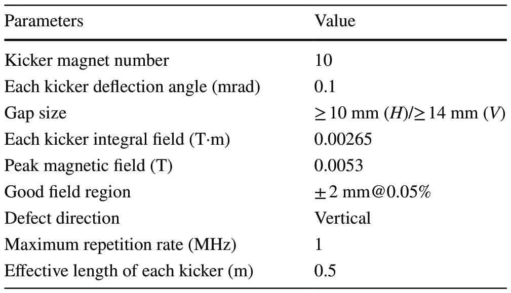
Table 1 Main required specifications of the kicker magnet
3 Kicker type selection
In the design of the kicker magnet, we considered factors,such as the magnetic field, magnet structure, pulsed power supply, and power consumption.The first option for the kicker type is a strip-line kicker [23—26].Strip-line kickers differ from traditional kicker magnets.They use transverse electromagnetic (TEM) waves produced by a kicker structure to deflect electron beam bunches.They consist of a vacuum chamber, two parallel electrodes, and an electrode flange.The strip-line kicker is driven by an equal-amplitude but opposite-polarity pulse power supply.The characteristic impedance of the strip line matches the terminating loads.The required transverse deflection voltage was calculated as follows:
whereUis the transverse deflecting voltage in volts,θis the deflection angle for each kicker in radians,Eis the electron beam energy in eV,dis the gap between the two blades in meters, andLkis the kicker effective length in meters.The advantage of this type of kicker is that the pulse edge can be very fast and the pulse width can be very small.If the pulse width is sacrificed to obtain a better pulse waveform,then the power consumption of the entire machine increases at a frequency of 1 MHz.For an electron beam energy of 8 GeV, a practical effective magnet length of 750 mm, a gap size of 15 mm, a deflection angle of 0.1 mrad, and a pulse of approximately 16 kV are required.Assuming a pulse width of 30 ns, the power consumption of a single kicker was 154 kW.It is difficult for power consumption and semiconductor switch systems to satisfy these requirements.Repetitive stability at such high frequencies is difficult to achieve, and mature commercial pulse power sources have a repetitive stability of only 1%.
The second option for the kicker type is a distributed-type transmission-line kicker [27—29].A distributed kicker consists of several sections that approximate the transmission line.It consists of inductive sections formed by two parallel electrodes and magnetic cores interleaved with a highvoltage capacitance to the ground, resembling the equivalent circuit of a transmission line with a specified characteristic impedance [30—32].The magnetic cores are attached between high-voltage capacitance plates.Each section consists of a magnetic core, together with excitation copper and capacitance plates.The fill time of the kicker is the delay time required for the pulse waveform to go past the kicker sections.The fill time of the kickerτis given as follows:
wherenis the section number of the kicker,LSis the inductance of a section of the kicker in Henry, andCSis the capacitance of a section of the kicker in Farad.More attention should be paid to the filling time of a long transmission-line kicker.A ferrite-loaded transmission-line kicker topology was selected in the LCLS-II with a short leading-edge time and a filling time of approximately 100 ns.The prototype kicker system demonstrated reliable operation at 500 kHz.For this kicker topology, higher characteristic impedances are beneficial for increasing the cutofffrequency of the transmission line and reducing flat-top ripples; however,it is difficult to optimize the impedance matching of each transmission-line unit owing to the distributed parameters.However, structural implementation and manufacturing are difficult.
In addition, the SwissFEL uses a resonant kicker.The deflected electron beam bunches are located at the peaks and valleys of a continuous sine wave.This kicker type is suitable for the double-bunch mode with a small bunch separation time and low repetition rate but is not applicable for high-frequency continuous operation.
A lumped-inductance kicker has a relatively simple structure and is widely used in accelerator injection and extraction systems [33, 34].The Shanghai Synchrotron Radiation Facility (SSRF) uses this type of kicker [35], which has the characteristic of being an inductance load for a pulse power supply with relatively slow rise and fall times.For a lumpedinductance kicker, in series with a resistance, the rise time of the pulse current is exponential with a time constantτcalculated as follows:
whereLmis the kicker inductance, andRis the series resistance impedance.By optimizing the kicker and pulse power supply design, a rise time of more than a few hundred nanoseconds was achieved [36].It is important to consider the skin effect on excitation coils, with special attention given to the power consumption of both the coil and magnetic core,when such a system is used in high-frequency and fast-pulse exciting current applications.A ceramic chamber must be inserted into the kicker if the kicker is outside the vacuum,owing to eddy currents, thus increasing the pulse current to obtain a given deflection angle [37].A magnet must be applied to the vacuum technology to minimize the magnet aperture of the kicker.
A lumped-inductance kicker inside a vacuum chamber was developed for the SHINE beam switchyard.The kicker adopts single-turn coils to make the pulse leading-edge fast.Its total power consumption is lower than that of the stripline and transmission-line kickers.
4 Kicker magnet design
4.1 Basic structure of kicker
The basic structure of the kicker is illustrated in Fig.2.The excitation coil is composed of a one-turn coil configured with two rectangular copper slabs.Two C-shaped Ni-Zn ferrite cores were assembled in a window frame.The magnetic cores were fixed to a metal frame outside the cores.In-vacuum kicker magnets with a magnet yoke exhibit beam coupling impedances [38].Eddy current strips between the two ferrite C-shaped cores were used to reduce the beam coupling impedance.A kicker was installed in a common vacuum chamber, and the transition between the kicker magnets was reduced using eddy current strips.The kicker gaps were 16 mm in the vertical direction and 10 mm in the horizontal direction.The window-frame magnetic core had the dimensions of 50 mm × 30 mm.
4.2 Excitation coil of kicker
The kicker was excited using a single-turn coil made of a rectangular copper rod with the dimensions of 10 mm × 7 mm.The coil was made of oxygen-free copper.The kicker magnetic coil is equivalent to an inductive load,and its inductance can be estimated as follows:
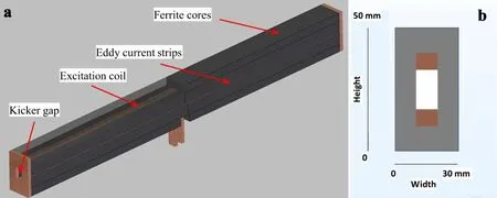
Fig.2 (Color online) Basic kicker structure of the threedimensional model (a) and twodimensional cross section (b)
whereμ0is the permeability of free space (4π × 10-7H/m),μris the permeability of the core material under the operating conditions,Nis the number of coil turns,Acis the core cross-sectional area in square meters,lgis the effective length of the air gap in meters, andlcis the length of the magnetic path in the core in meters.According to Eq.(4),the calculated inductance of the excitation coil is 1.1 μH,and after adding the leading wire inductance in the vacuum chamber, the total inductance of the kicker is approximately 1.3 μH.In addition, the inductance of the magnet can be calculated using a general-purpose three-dimensional (3D)electromagnetic simulation software.The advantage of using electromagnetic simulation software is that the coil model is more accurate, and the calculation result is more precise.We used COMSOL Multiphysics to calculate the coil inductance in two ways [39]: directly through the coil structure, and through the magnetic energy density.Based on these two methods, the calculation results for the kicker inductance are both 1.2 μH.
Another consideration in coil design is that the two excitation coils placed above and below each other exist in each other’s magnetic fields and are therefore subject to forces.The magnitudes of these forces were calculated using COMSOL to provide a reference for subsequent design.The calculation results of the coil force indicate that the forces on the coils are 1.5 × 10⁻⁸N in theX-direction and 2.1 N in the Y-direction with the setting current of 43 A.The force is in the negativeY-direction for the other coils, resulting in mutual repulsion.The coil was etched from a single copper block to reduce the repulsive force.
4.3 Magnetic field simulation of kicker
The required magnetic flux density in the aperture (By) of the kicker can be calculated using Eq.5.The excitation current(Ik) of the kicker can be calculated through Eq.6.
whereθis the deflection angle for the kicker in radians,Eis the beam energy in eV,Lkis the kicker effective length in meters,vis the velocity of the beam particles in meters per second,lgis the effective length of the air gap in meters,μ0is the permeability of free space (4π × 10-7H/m), andNis the number of turns of the kicker coil.Based on Eqs.5 and 6, the required magnetic flux density is 0.0053 T, and the required excitation current is 42.5 A.
The two-dimensional (2D) simulation results for the lumped-inductance kicker are shown in Fig.3a.The calculation results for the magnetic flux density in theX- andY-sections of the single-inductance kicker are shown.The maximum magnetic flux density was observed at the four inner corners.The required magnetic flux density was 0.0053 T, and hence, the magnetic core was hardly saturated.The distribution of magnetic fieldBXalong theY-direction is shown in Fig.3b.The simulation results showed that the magnetic field homogeneity was < 0.5% in the plane range of 8—14 mm.The distribution of magnetic fieldBYalong theX-direction is shown in Fig.3c.The three-dimensional(3D) simulation results of the single-inductance kicker are shown in Fig.3d.The color scale of the kicker magnet core in Fig.3d indicates the magnetic fields, and the red lines in the coil indicate the current following the streamlines.Figure 3e shows the change curve of the magnetic flux density along theZ-direction at the center of the lumped-inductance kicker.The simulation results showed that the integral of the magnetic field was 0.00273 T·m, the effective length of the magnetic core was 500 mm, and the excitation current setting was 43 A.The 2D and 3D simulation results indicated that the design satisfied the physical requirements.
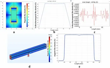
Fig.3 (Color online) Magnetic field simulation result of the kicker magnet.a is two-dimensional simulation result, b is the magnetic field BX along the Y-direction, c is the magnetic field BY along the X-direction, d is the three-dimensional simulation results, and e is the magnetic flux density along the Z-direction
4.4 Magnetic core material and structure
Magnetic core materials used in electromagnetic design regularly contain silicon steel, iron powder cores, amorphous alloys, and ferrites (manganese-zinc, nickel-zinc,and magnesium-zinc).In a lumped-inductance kicker, the magnetic core adheres to the excitation coils.The magnetic cores are insulated from the excitation coils.The excitation current is a high-frequency fast-pulse waveform.The spectral content is relatively high.Silicon steel, iron powder cores, and amorphous alloys have low resistivities and do not satisfy the insulation requirements of magnetic cores and excitation coils.If used, additional insulation measures should be implemented; thus, the kicker gap must be changed.Ferrite is a ceramic-like magnetic material with a high electrical resistance and wide frequency range.A high electrical resistance is desirable for the cores of pulsed magnets to reduce eddy currents.Nickel-zinc ferrite (DN5H), which has better high-frequency characteristics, is used in kicker magnets.Some material parameters have been previously measured: the relative initial permeability is 50 from DC to 50 MHz, and the saturation flux density is 0.37 T.Both fulfill the requirements of the kicker with a maximum central magnetic field of approximately 0.0053 T.
There are two basic structural designs for ferrite magnetic cores: the integral window type and the spliced window type.The integral window type ensures a good field region of the kicker, but leads to an assembled structure of the kicker excitation coil to match the installation requirements.To reduce the difficulty in manufacturing the kicker excitation coil, two C-type magnetic cores were used to form a window-frame yoke.The core was stacked with several ferrite blocks.
4.5 Power consumption and cooling of kicker magnet
The power consumption of the kicker includes two parts: the power consumption caused by the skin effect of the excitation coil under a high-frequency current and the power consumption of the ferrite cores.As the magnet is installed in a vacuum chamber, issues related to power consumption and heat dissipation must be considered.Assuming a pulse current frequency of 1 MHz, a wire length of 1.5 m, and a duty cycle of 0.5, the calculated resistance power consumption of the excitation coil was approximately 20 W.If thermal radiation is not considered, the generated heat is transmitted along the copper coil to the outside of the vacuum chamber.Applying the calculated power consumption to the coil and adding boundary conditions (the ends of leads are maintained at 25 °C), we obtain the temperature distribution on the surface of the coil.The highest temperature was approximately 92 °C,which was observed at the center of the upper electrode.The magnetic core was installed outside the coil and covered with a stainless-steel pressure plate.To simplify the calculations, factors, such as the thermal contact resistance between the magnetic core and the coil, the thermal conductivity coefficient of the magnetic core material, and the thermal resistance between the magnetic core and the stainless-steel pressure plate, were not considered.However, after adding these factors, the temperature of the coil decreased to a certain extent.
The core power consumption is primarily due to hysteretic losses, which are proportional to the area of the hysteresis loop when a unit volume of the core undergoes one cycle.This energy is converted into heat.Steinmetz developed an empirical formula for hysteretic loss [40].According to this formula,the hysteretic loss per unit volume can be expressed as follows:
whereK1andαare constants that depend on the material properties and other factors, whereK1= 0.03 anda= 1.69 for our ferrite materials, and η is the Steinmetz coefficient.Steinmetz obtained a value of approximately 1.6 forηfor several materials;fis the operating frequency; andBmis the maximum magnetic flux intensity on the hysteresis loop.The core volume and magnetic flux density of the single-inductance kicker are extremely small.From Eq.7, the calculated core loss (16 W) is very small compared with the coil power consumption, and the heat can be easily conducted on the vacuum chamber surface using a heat conduction tape.
5 Prototype and magnetic measurement of kicker magnet
5.1 Prototype of kicker magnet
An in-vacuum design scheme was adopted for the structure of the kicker, and the kicker was designed for hoisting installation to simulate the installation scheme of SHINE.A kicker was placed in the vacuum chamber during the prototype development stage.The kicker was installed on the bottom plate and could be reliably collimated and fixed in three directions.Finally, the kicker and bottom plate were fastened to the vacuum chamber using a positioning bolt component.Figure 4 shows the kicker model and a photograph.According to the physical layout requirements, 2—3 kicker magnets were placed in a vacuum chamber during the facility construction stage.The kicker was excited by a pulsed power supply, which was connected to the kicker through a feedthrough that isolated the vacuum chamber from the outside.Structural optimization shortens the length of the feedthrough to reduce the inductance as much as possible.The feedthrough inductance was 0.1 μH.
5.2 Pulsed excitation power supply
A pulsed excitation power supply is suitable for the stable and reliable operation of the kicker.A power supply must operate at a high repetition rate.The power supply uses atypical switching-mode topology.A schematic of the power supply and output current waveform is shown in Fig.5,where S1 is a metal—oxide—semiconductor field-effect transistor (MOSFET), and L1 represents the inductance of the kicker.The MOSFET was used to switch the current on and offfor pulse generation.When the MOSFET was turned on, the current delivered to the kicker closely resembled an underdamped step response.When the MOSFET was turned off, the energy stored in the kicker magnet inductance dissipated back through R2 and D1.The specifications are listed in Table 2.

Fig.4 (Color online) Model and photograph of the kicker

Fig.5 Schematic (a) and simulation waveform (b) of the pulsed excitation power supply

Table 2 Required specifications of the pulsed excitation power supply for the kicker magnet
5.3 Measurement system setup
The measurement of a pulsed magnetic field is based on electromagnetic inductive principles [41].A custom-made inductive coil was used to measure the voltage induced by the pulsed magnetic field.The magnetic flux waveform was obtained after digital integration using an oscilloscope.To improve the measurement bandwidth of a point measurement coil, it is necessary to reduce its inductance and increase its internal resistance.However, the small cross-sectional area of the coil makes it difficult to measure the magnetic flux accurately.The low magnetic flux density (0.0053 T)resulted in a low induced voltage in the point measurement coil.During the test and acceptance, a wideband current monitor was used to measure the pulsed excitation current,and an integral coil was used to measure the induced voltage signal of the pulsed magnetic field.Both waveforms were recorded for the magnetic field measurements.The layout and a photograph of the magnetic field measurements are shown in Fig.6.
5.4 Measurement results
Figure 7 shows the magnetic field measurement waveforms and the results of the temperature rise test.The magnetic flux waveform exhibited excellent linearity and consistency with the pulsed excitation current.Figure 7a shows the waveforms of the pulsed excitation current, induced voltage, and magnetic flux a repetition rate of 10 kHz.Figure 7b shows the waveforms of the pulsed excitation current and magnetic flux at a repetition rate of 1 MHz.Figure 7c shows the waveforms of the pulsed excitation current, induced voltage, and magnetic flux at a repetition rate of 100 kHz.Figure 7d shows the numerical results for the pulsed excitation current, induced voltage, and magnetic flux at a repetition rate of 10 kHz.The cross-sectional area of the single-turn homemade inductive coil was 6 mm × 900 mm.The attenuation coefficient of the attenuator was 10 dB, which is 3.16 times that of the induced voltage.The pulsed excitation current was 43.2 A,which generated a magnetic flux density of 0.0053 T in the kicker gap.The peak-to-peak induced voltage was 64.3 V.The magnetic flux was 17 μWb, and thus, we could calculate the magnetic flux density as 0.0057 T and the integral magnetic field as 0.00283 T·m, which is higher than the required integral magnetic field of 0.00265 T·m.The induced voltage repetitive stability was 0.038%, the magnetic flux repetitive stability was 0.032%, and the pulsed excitation current repetitive stability was 0.011%.Table 3 summarizes the results of the magnetic field measurements.

Fig.6 (Color online) Layout (a) and photograph (b) of the magnetic field measurement
A thermal imager was used to measure the temperature increase in the kicker.The temperature rise test was performed under open-air conditions at a peak pulsed excitation current of 43 A and a repetition rate of 1 MHz.The maximum test temperature in Fig.7e and f is 30 °C with an environmental temperature of 15 °C.The kicker operates in a vacuum environment, and the temperature is high owing to the poor cooling effect.
6 Conclusion and further work
In this study, a high-repetition-rate lumped-inductance kicker prototype was proposed for the beam switchyard of SHINE.A kicker was applied to the single-turn coil in a vacuum chamber.The physical requirements, selection, and detailed design of the kicker, such as the basic structure,excitation coil, magnetic field simulation, magnetic core material, and magnet power consumption, are presented.Furthermore, a kicker magnet prototype was constructed,and experiments were conducted to verify the design and measure the magnetic field of the kicker.The main conclusions and directions for future work are as follows:
1.A kicker prototype with a magnetic field pulse width of 600 ns, an operation repetition rate of 1 MHz, and a kicker gap central field of approximately 0.0053 T was developed.It can provide a deflection angle of 0.1 mrad for 8 GeV electron beam bunches in a bunch-by-bunch distribution mode.The experimental results showed that the developed lumped-inductance kicker prototype satisfies the physical requirements of SHINE.
2.Lumped-inductance kicker magnets have the advantages of a simple structure and good magnetic field quality.In-vacuum technology was used to reduce the kicker gap and excitation current requirements.The optimized design of the magnet structure and pulsed excitation power supply allowed the kicker to operate at a repetition rate of 1 MHz.
3.The proposed lumped-inductance kicker provides an innovative solution for high-repetition-rate XFEL facilities, not only for beam distribution but also for bunchby-bunch phase shifters.
4.Eddy current strips were not manufactured or installed during the prototype development.Eddy current strips are extensively used in SSRF and will be installed in the next version of the kicker.
5.The latest printed-circuit-board magnetic field measurement coils and 3D moving platforms are currently being designed.They can be used for more accurate magnetic field measurements and can better capture the distribution and uniformity of the magnetic field.
6.Further optimization of the pulsed excitation power supply design based on the step-function response of second-order circuits and silicon carbide MOSFETs is underway.The optimization objectives include reduced pulse edge, improved pulse flat top, improved repetitive stability, and reduced power consumption.

Fig.7 (Color online) Magnetic field measurement waveforms.a—d are magnetic field measurement waveforms; e and f are the results of the temperature rise test
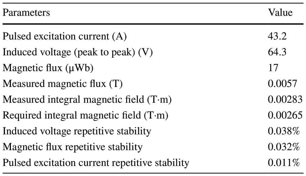
Table 3 Magnetic field measurement results
Author contributionsAll authors contributed to the study conception and design.Material preparation, data collection and analysis were performed by YL and MG.The first draft of the manuscript was written by YL, and all authors commented on previous versions of the manuscript.All authors read and approved the final manuscript.
Data availabilityThe data that support the findings of this study are openly available in Science Data Bank at https:// cstr.cn/ 31253.11.scien cedb.14867 and https:// doi.org/ 10.57760/ scien cedb.14867.
Declarations
Conflict of interestThe authors declare that they have no competing interests.
 Nuclear Science and Techniques2024年2期
- Nuclear Science and Techniques的其它文章
- Measurement of the neutron-induced total cross sections of natPb from 0.3 eV to 20 MeV on the Back-n at CSNS
- Nuclear charge radius predictions by kernel ridge regression with odd-even effects
- Unbound 28 O, the heaviest oxygen isotope observed: a cutting-edge probe for testing nuclear models
- Development of CONTHAC-3D and hydrogen distribution analysis of HPR1000
- Total ionizing dose effect modeling method for CMOS digital-integrated circuit
- A fast forward computational method for nuclear measurement using volumetric detection constraints