
Solid-liquid flow characteristics and sticking-force analysis of valve-core fitting clearance
2024-01-11 08:07JinyuanQIANJiaxiangXUFengpingZHONGZhenhaoLINTingfengHUAZhijiangJIN
Jin-yuan QIAN ,Jiaxiang XU ,Fengping ZHONG ,Zhenhao LIN ,Tingfeng HUA ,Zhijiang JIN,3✉
1Institute of Process Equipment,College of Energy Engineering,Zhejiang University,Hangzhou 310027,China
2Zhejiang Academy of Special Equipment Science,Hangzhou 310009,China
3Institute of Wenzhou,Zhejiang University,Wenzhou 325036,China
Abstract: External contamination particles or wear particles corroded by a valve body are mixed into the fluid.As a result,when the fluid enters the fitting clearance of the valve core,it can cause an increase in resistance and lead to sticking failure of the valve core.This paper analyzes solid-liquid flow characteristics in fitting clearances and valve-core sticking based on the Euler-Euler model,using a typical hydraulic valve as an example.The impact of particle concentration and diameter on flow characteristics and valve-core sticking force was analyzed.The highest volume fraction of particles was in the pressureequalizing groove (PEG),with peak values increasing as the particle diameter increased.The sticking force increased with increasing particle concentration.When the particle diameter was 12 μm,the sticking force was the largest,making this the sensitive particle diameter.Particle distribution and valve-core sticking force were compared for oval,rectangular,and triangular PEGs.The fluid-deflection angles in oval and rectangular PEGs were larger,and their values were 32.83° and 39.15°,respectively.The fluid-deflection angle in the triangular PEG was relatively small,less than 50% that of the oval or rectangular PEGs.The particle-volume-fraction peaks in oval,rectangular,and triangular PEGs were 0.0317,0.0316,and 0.0312,respectively.The sticking forces of oval,rectangular,and triangular PEGs were 4.796,4.802,and 4.757 N,respectively when the particle diameter was 12 μm.This work provides a reference for design and research aimed at reducing valve-core sticking.
Key words: Solid-liquid flow characteristics;Valve core;Sticking force;Euler-Euler model
1 Introduction
In the fluid pipeline system,the control valve,as the core component of fluid medium regulation,is widely used in power plants (Ye et al.,2021;Lin et al.,2023),coal chemical industry (de Almeida Moreira et al.,2021;Zhang et al.,2021),biomedical (Natarajan et al.,2017),hydrogen energy (Yu et al.,2023),and other fields.The valve core of control valve that controls the flow direction and flow cross-sectional area of the medium,determines the flow,pressure,and other parameters of the medium (Wu et al.,2021;Dong et al.,2022;Lu et al.,2022).However,when the valve core is subjected to excessive resistance,its response time increases and its action slows,which can even cause it to become stuck.This seriously threatens the stability and safety of valve operation.
A number of factors contribute to valve-core sticking,which can be roughly divided into mechanical,hydraulic,thermal,and pollution factors.Mechanically,valve-core sticking is caused by valve-assembly or machining error and mechanical structure (Duan and Nielsen,2007;Lisowski et al.,2018;Lu et al.,2020,2021).In terms of hydraulics,the force of the medium in the valve causes an unbalanced moment on the end face of the valve core,which leads to eccentricity of the valve core and increases resistance to its movement (Shi,2014;Qian et al.,2021).Meanwhile,the medium in the valve or the external fluid directly acts to hinder the movement of the valve core or cause it to deform excessively (Beune et al.,2012;Liu et al.,2019).Thermally,when the medium flows through the valve port,the heat absorbed by the medium of the valve core generates different degrees of thermal expansion due to the viscosity-temperature effect of the fluid,resulting in reduction of the fitting clearance (Yan et al.,2013;Zhao et al.,2015;Xu et al.,2019;Chen et al.,2021).Finally,with regard to pollution,the resistance of the valve core increases due to external contamination particles or wear particles corroded by valve trims which remain in the fitting clearance between the valve body and valve core.It is worth noting that medium polluted with external particles not only further wears the valve core and valve body (Brazhenko et al.,2020;Liu et al.,2020),but also enters easily into the fitting clearance,resulting in the valve core becoming clamped or even stuck (Yang and Rodkiewicz,1996).In particular,approximately 70%of hydraulic system failure is due to oil pollution causing the valve core to stick.In this study,we took a hydraulic valve as the research object and focused on the valve-core sticking phenomenon caused by particles.
The contamination particles flow complexly with the fluid in the valve (Guatemala et al.,2012;Lin et al.,2020).After the contamination particles enter the fitting clearance of the valve core with the fluid,some of them flow out of the fitting clearance,while some remain in it.Therefore,it is very important to study the movement law of particles in the micro-scale channel for optimal design of the valve core.Iyengar (1976)obtained the relationship between particle hardness,particle concentration,valve-core stationary time,and sticking force through experiments,and proposed the concept of “sensitive particle diameter” for the first time.Fitch (1984) clarified through experiments that valve-core sticking in a hydraulic valve is mainly caused by deposition of solid particles at the fitting clearance inlet and other parts.Chen et al.(2018)studied the particle migration trajectory in the fitting clearance of a valve core with a rectangular pressureequalizing groove (PEG) by numerical simulation.
The presence of contamination particles in the fitting clearance causes the valve core to generate a large blocking force,which in turn affects the movement performance of the valve core.Fan et al.(2019)obtained the variation curve of friction force during valve-core movement through experiments based on the surface morphology and size of particles in the fitting clearance.The PEG can effectively reduce the imbalance force of the valve core and the concentration of particles in the fitting clearance.Hong and Kim(2016) proposed a valve-core structure with a spiral PEG and showed that this structure can effectively reduce the inhomogeneous pressure profile in the fitting gap.Zeng et al.(2012) simulated the sticking phenomenon caused by taper and eccentricity of the valve core,and analyzed the influence of the number,shape,size,and concentricity of PEGs on sticking force.
It can be concluded that there have been some remarkable studies on particle flow characteristics with regard to fitting the gap of a valve core.However,most studies are specific to agglomeration and particle accumulation in the fitting clearance.The variation of the friction force on the valve core due to contaminated particles is still poorly studied.Therefore,we analyzed a typical hydraulic valve,looking at the solid-liquid flow characteristics in the fitting clearance and sticking of the valve core based on the Euler-Euler model.First,we established a numerical model for solid-liquid two-phase flow of a 2D valve-core fitting clearance.Then,we analyzed the influence of particle-characteristic parameters (concentration,diameter) on particle distribution and valve-core sticking force.Finally,we compared the effects of three types of PEG on particle distribution and valve-core sticking force.This work therefore provides a reference for reducing valve-core sticking.
2 Model description
2.1 Euler-Euler model
We used hydraulic oil with contamination particles as the medium,and adopted the Euler-Euler model to solve the solid-liquid two-phase flow in the valvefitting clearance.In computational fluid dynamics(CFD),the Euler-Euler model is often used to solve multiphase flows and interactions between phases,and its computational accuracy is higher than that of the mixture model (van Wachem and Almstedt,2003).
The continuity equation for thekphase in the Euler-Euler model is as follows:
wheretis the time,αkis the volume ratio ofkphase,ρkis the density ofkphase,vkis the velocity ofkphase,is the derivation of mass transfer fromptokphases,andis the derivation of mass transfer fromktopphases.
The momentum equation of thekphase in the Euler-Euler model is as follows:
whereFkrefers to external volume force,Flift,krefers to lift force,refers to virtual mass force,Rpkrefers to interaction force between phases,Prefers to pressure (shared by the phases),vpkandvkprefer to phase velocities,grefers to gravitational acceleration,andrefers to the pressure strain of thekphase,and its value is as follows:
whereμkandλkrefer to the shear viscosity coefficient and bulk viscosity coefficient of thekphase,respectively,andIrefers to the unit tensor.
The volume fraction equation of each phase can be obtained from the continuity equation:
whereρrkis the phase reference density,that is,the volume-average density of thekphase in the fluid domain.
2.2 Fluid domains and grids
We studied a typical hydraulic slide valve that mainly consisted of a valve body,valve sleeve,and valve core,as shown in Fig.1.
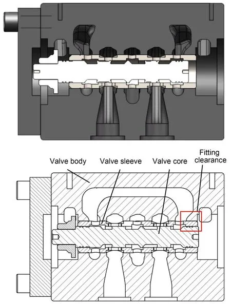
Fig.1 Schematic diagram of hydraulic valve: (a) model diagram;(b) engineering drawing
There was a fitting clearance between the valve core and valve sleeve.The valve core was provided with more than one PEG.The domain of fitting clearance was simplified into a 2D flow domain model without considering the influence of eccentricity,inclination,or inverted cone when the valve core was matched,as shown in Fig.2a.To compare the influence of PEG section shape on particle distribution,we selected three PEG shapes,with oval,rectangular,and triangular sections.The depth and width of the three PEGs were guaranteed to be the same,but the crosssection shapes were different,as shown in Fig.2b.When the 2D flow domain was discretized,the cells were quadrilateral structured grids.The global grid size was 5 μm,the minimum-size flow domain had a grid layer of four layers,and the total number of grids was 19576.
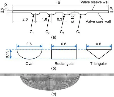
Fig.2 Domain and mesh (unit: mm): (a) 2D flow domain with PEG;(b) types of PEG;(c) meshes of domain.p1 is the pressure inlet,p0 is the pressure outlet,and G1-G4 are the PEGs
2.3 Boundary conditions
The fluid was hydraulic oil mixed with contamination particles,and the flow in the fit clearance was a solid-liquid two-phase flow.We assumed the fluid to be an incompressible,constant Newtonian fluid.In the Euler-Euler model,the first phase is the continuous phase (the hydraulic oil) and the second phase is dispersive (solid particles).The properties of hydraulic oil with particles are shown in Table 1.

Table 1 Properties of hydraulic oil with contamination particles
The density of the oil was 900 kg/m3,and the dynamic viscosity was 0.04050 Pa·s.The density of the solid particles was 7500 kg/m3,and the dynamic viscosity was 0.00001 Pa·s.Different particle diameters can be set in the Euler-Euler model,and diameters were selected ranging from 3 to 18 μm.The inlet was set to different particle concentrations (c),with particle volume fractions of 1%,3%,5%,and 7%.The inlet was the pressure inlet,p1=8.56 MPa.The outlet was the pressure outlet,p0=0.The walls were no-slip.We selected the Syamlal-O’brien model for granular viscosity in the Euler-Euler model.For the drag-phase interaction,we chose the Schiller-Naumann model,and the lift used the default value,implying no phase separation.Our calculation of the Reynolds number was much smaller than the critical Reynolds number(approximately 700) of the concentric annular clearance with ring groove (Sigloch,2014),so the fluid flowed in the fitting clearance as laminar flow,and we used the Laminar viscosity model.
3 Results and discussion
3.1 Flow rate in the fitting clearance
To verify the accuracy of the fluid-domain calculation,we compared the outlet flow calculated by the simulation with that calculated by the theory.The flow-calculation model of the fitting clearance between the valve core and valve body is a concentric annular clearance model as shown in Fig.3.
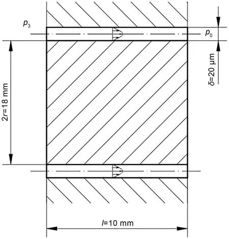
Fig.3 Fitting clearance model between valve core and body
The flow-calculation formula for the concentric annular clearanceQTis obtained from the clearanceflow formula for the two plates (San Andres,2006).
whereDis the diameter of the valve core,μis the kinematic viscosity,δis the fitting clearance between the valve core and valve body,lis the length of the fitting clearance,and Δp=p3-p0,wherep3is the inlet pressure of the fitting clearance.
Post-processing in FLUENT was used to obtain the outflow rate of the fitting clearance.They-direction defaulted to unit 1 in the 2D model.Because(2r=D) in the calculation model,the fitting clearance could be expanded into a gap model of a parallel plate along the circumferential direction,that is,we were able to obtain the flow rateQCof the 3D annular clearance by multiplying πDbased on the 2D simulation structure.The outlet flow rates for the fitting clearance obtained by both theoretical and simulation calculations are shown in Table 2.The theoretically simulated flow rate was slightly larger than the simulationcalculated flow rate,with a maximum error of 7.6%.This is because the flow velocity can only form a parabolic distribution after the oil passes through an initial length,not immediately after it enters the flow channel.Therefore,the theoretical calculation is slightly larger than the simulation calculation,taking into account the effect of the initial phase of the laminar flow in practice.The results show that the numerical methods and simulation results used in this paper are reliable.
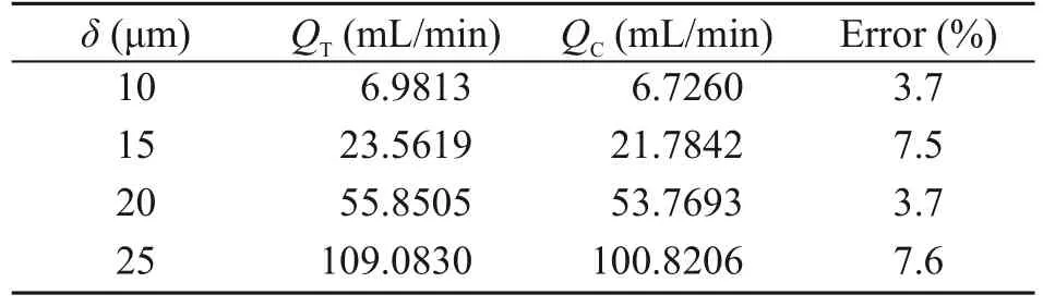
Table 2 Flow of theoretical calculation and numerical simulation at different fitting clearances
3.2 Effect of particle parameters on flow characteristics and sticking force
A coordinate system was set up with the center of the fitting clearance inlet as the origin and the particle volume fraction and pressure were extracted at the center line of the fitting clearance,with the center line as thex-axis and the particle volume fraction or pressure as they-axis.The pressure distribution in the fitting clearance is shown in Fig.4.Hydraulic oil with contamination particles entered from the fitting clearance inlet and passed through the PEGs.In the PEGs,the pressure distribution was almost equal.The pressure drop was a stepwise descent.
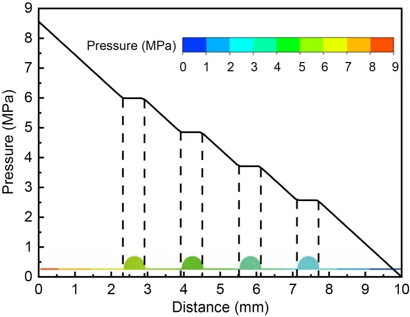
Fig.4 Distribution of pressure in fitting clearance
The variable curve of particle volume fraction in the fitting clearance with different particle diameters(withc=3%) is shown in Fig.5.A particle diameter of 3 μm is taken as an example.The particle volume fraction in the inlet channel of the fitting clearance was 0.0300,while in the fitting-clearance channel between the first adjacent PEGs,it was approximately 0.0302.The particle volume fraction was the highest in the PEG,with a peak value that increased with the increase of particle diameter.This is because when the hydraulic oil enters the PEG,the flow channel widens,the flow velocity decreases,and particles are retained in the PEG.The peak values in different PEGs were also different along the flow direction,increasing from the first PEG to the fourth PEG.
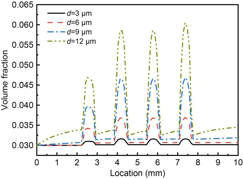
Fig.5 Distribution of particles in fitting clearance with different particle diameters d with c=3%
To analyze the variation of particle volume fraction in different PEGs,we extracted the particle volume fraction along the path perpendicular to the flow direction,as shown in Fig.6.The figure shows that the particle volume fraction was higher near the valve sleeve wall,and first decreased and then increased as it gradually approached the wall of the valve core.This was caused by the viscosity of the hydraulic oil.The agglomeration phenomenon formed near the valve sleeve wall of the PEG,and the deposition phenomenon formed at the bottom of the PEG.From the first to the fourth PEGs,the particle volume fraction at the bottom of the first PEG gradually decreased,while it was similar at the bottom of the second and third PEGs.It is evident that the first PEG had a great interception effect on contamination particles and a marked capacity to store pollution.
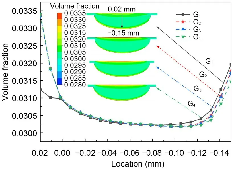
Fig.6 Distribution of particles in different PEGs
We then extracted the particle volume fractions in the first and second PEGs with different particle diameters,as shown in Fig.7.As particle diameter increased,the particle volume fraction at each position in the first PEG increased,especially on the upper and lower walls of the PEG.This is due to the fact that when particle diameter is larger,the space occupied by the same number of particles and the density are also larger,and the particles are more likely to cluster on the walls because of the action of hydraulic oil viscosity.It can be seen from Fig.7b that in the second PEG,as the particle diameter increased,the particle volume fraction at the wall increased significantly,while it increased only slightly in other regions.The particle volume fraction near the bottom wall was obviously higher than that near the valve sleeve wall in the first PEG,but the opposite phenomenon occurred in the second PEG.
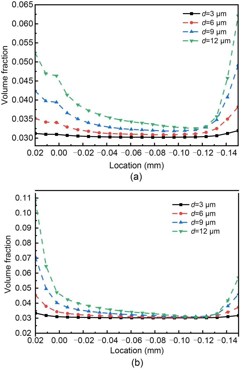
Fig.7 Distribution of particles in different PEGs: (a) G1;(b) G2
The hydraulic oil mixed with contamination particles of different diameters showed different aggregation effects when filtered through the fitting-clearance flow field,which affected the sticking force of the valve core (namely the surface friction of the valve core).The sticking forces for different particle concentrations and particle diameters were extracted and calculated in FLUENT with post-processing.Fig.8 shows the variation curves of sticking force for different particle concentrations and particle diameters.The sticking force first increased and then decreased with the increase of particle diameter.When the particle diameter was 12 μm,the sticking force reached its maximum value;when the particle diameter was 9-12 μm,the valve-core stuck force was larger.The particle diameter was defined as the “sensitive particle diameter” when the sticking force reached its maximum with a fixed fitting clearance.Therefore,when the particle diameter was 12 μm in a particle-concentration range of 1%-5%,the maximum sticking force was generated,and the sensitive particle diameter was 12 μm.At higher particle concentrations,the sticking force also rose,especially when the particle concentration was 7% and the sensitive particle diameter was 9 μm.The sticking force was too large and easily caused the valve to clamp or even stick.Thus,in the pipeline system,the appropriate scale of filter or filter core should be used to filter out particles with diameters near the sensitive particle diameter.This will reduce valve wear and sticking.
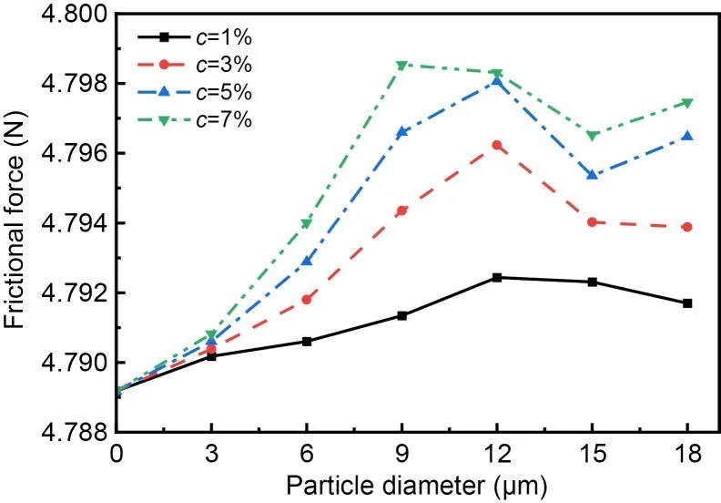
Fig.8 Sticking forces with different particle diameters and concentrations
3.3 Effect of PEG on flow characteristics and sticking force
The variable curve of particle volume fraction in the fitting clearance with different types of PEG (withc=3% andd=3 μm) is shown in Fig.9.The particlevolume-fraction was the highest in the rectangular PEG,the second highest in the oval PEG,and the lowest in the triangular PEG,with the following respective peaks: 0.0317,0.0316,and 0.0312.The triangular PEG greatly reduced the particle volume fraction at the center of the fitting clearance.
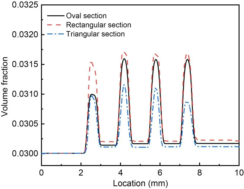
Fig.9 Distribution of particles in fitting clearance with different types of PEG
The particle-volume-fraction profiles extracted in the first and second PEGs (which had different shapes) are shown in Fig.10.It is apparent that for all three types of PEG,the particle volume fraction near the wall was larger,and showed the same law of variation.For the rectangular PEG,the particle volume fraction near the valve-sleeve wall was larger than that near the valve-core wall.The particles were mainly concentrated on the left and right walls of the rectangular PEG (highlighted by the circle in the figure).For the triangular PEG,the particle volume fraction near the valve sleeve wall was lower than that near the valve-core wall.The particles were mainly concentrated at the bottom of the triangular PEG (highlighted by the circle in the figure).The triangular shape greatly increased the particle volume fraction at the bottom of the PEG,and the agglomerative effect was very significant.
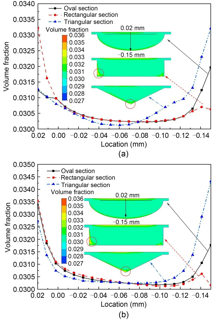
Fig.10 Distribution of particles with different types of PEG: (a) G1;(b) G2
When the fluid enters the PEG,the flow direction changes and the jet angle is formed.The jet angle between the velocity direction and the horizontal direction is defined as the fluid-deflection angle (θ).The distributions of velocity and fluid-deflection angle in fitting clearances with different types of PEG are shown in Fig.11.The flow velocity was higher in the middle region of the PEG and lower in the region near the wall,which is consistent with the distribution of particle volume fractions.It can be seen from Fig.11 that the fluid-deflection angles in the oval and rectangular PEGs were larger,with values of 32.83°and 39.15°,respectively.The fluid velocity near the valve-body wall was greatly reduced.Due to the high particle density and large inertia,the particles maintained an approximately linear motion within the fitting clearance,but the original velocity could not be maintained.The resistance caused by the velocity difference between the solid and liquid phases made the particles start to slow down or even stop,so that the particle volume fraction at the wall surface was higher.Meanwhile,it can be seen that the particle volume fraction was higher at the inner wall of the entrance side of the rectangular PEG.For the triangular PEG,the fluid-deflection angle was relatively small,less than 50% that of the oval or rectangular PEGs.The flow rate was large,which allowed a fraction of the particles to exit the PEGs.However,a large number of particles had already accumulated at the bottom of the PEG,and were not carried by the hydraulic oil to the PEG of the latter.
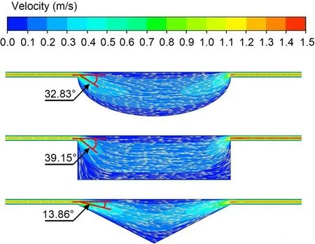
Fig.11 Distribution of velocity in fitting clearance with different types of PEG
Different types of PEG exhibited different particle-accumulation effects,which have a large impact on the sticking force on the valve core (Fig.12).Under the influence of contamination particles,the sticking force was consistent with the distribution of particles in different types of PEG.The sticking force was the highest on the rectangular PEG,the secondhighest on the oval PEG,and the lowest on the triangular PEG.It was mainly caused by the particle distribution on the center line of the fitting clearance.It can be seen from Fig.12 that the difference in sticking force between the oval and rectangular PEGs was very small,while the sticking force in the triangular PEG was significantly reduced.When the fitting clearance size was determined,we found the sensitive particle diameter of the three PEGs to be 12 μm;this produced the maximum sticking force.The sticking forces of the oval,rectangular,and triangular PEGs were 4.796,4.802,and 4.757 N,respectively,when the particle diameter was 12 μm.In the triangular PEG,the particle volume fraction in the fitting clearance and the sticking force in the valve core were reduced to some extent,and the particles were intercepted in the groove.Thus,a triangular PEG with a small fluiddeflection angle and a strong capacity to store contamination particles at the bottom is optimal for the valve core,because it alleviates the phenomenon of valvecore sticking.
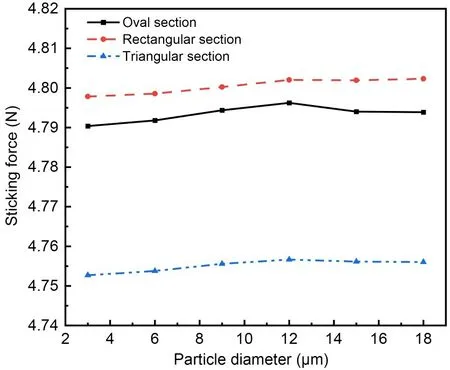
Fig.12 Sticking forces with different types of PEG
4 Conclusions
In this paper,a typical hydraulic spool valve is taken as an example for analysis of the solid-liquid flow characteristics in the fitting clearance as well as sticking of the valve core,based on the Euler-Euler model.We looked at the effects of particle concentration and particle diameter on particle distribution and valve-core sticking force.The volume fraction of particles in the PEG is the highest,and the peak value also increases with larger particle diameter.The sticking force increases as particle concentration increases.As the particle diameter increases,the sticking force first increases and then decreases.When the particle diameter is 12 μm,the sticking force is the largest,indicating that this is the sensitive particle diameter.Thus,in the pipeline system,the appropriate scale of the filter or filter core is used to filter out particles with diameters near the sensitive particle diameter to reduce valve wear and sticking.
We compared the particle distribution and valvecore sticking force for oval,rectangular,and triangular PEGs.The fluid-deflection angles in oval and rectangular PEGs are larger,with values of 32.83° and 39.15°,respectively.The fluid-deflection angle in a triangular PEG is relatively small,less than 50% that of an oval or rectangular PEG.The particle volume fraction is the highest in a rectangular PEG,the second highest in an oval PEG,and the lowest in a triangular PEG,with the peaks of particle volume fraction being 0.0317,0.0316,and 0.0312,respectively.The sticking forces for oval,rectangular,and triangular PEGs are 4.796,4.802,and 4.757 N,respectively,when the particle diameter is 12 μm.Thus,a triangular PEG with a small fluid-deflection angle and strong capacity to store contamination particles at the bottom is optimal for the valve core,which alleviates the phenomenon of valve-core sticking.
Acknowledgments
This work is supported by the National Key Research and Development Program of China (No.2021YFB2011300)and the National Natural Science Foundation of China (No.52175067).
Author contributions
Jin-yuan QIAN designed the research.Jiaxiang XU and Fengping ZHONG processed the corresponding data.Jiaxiang XU wrote the first draft of the manuscript.Zhenhao LIN and Tingfeng HUA helped to organize the manuscript.Zhijiang JIN revised and edited the final version.
Conflict of interest
Jin-yuan QIAN,Jiaxiang XU,Fengping ZHONG,Zhenhao LIN,Tingfeng HUA,and Zhijiang JIN declare that they have no conflict of interest.
 Journal of Zhejiang University-Science A(Applied Physics & Engineering)2023年12期
- Journal of Zhejiang University-Science A(Applied Physics & Engineering)的其它文章
- Key technologies and development trends of the soft abrasive flow finishing method
- Enhanced mixing efficiency for a novel 3D Tesla micromixer for Newtonian and non-Newtonian fluids
- Numerical modeling and experimental study of microstamping process for fabricating microchannels using thin sheets of titanium
- Influence of adjacent shield tunneling construction on existing tunnel settlement: field monitoring and intelligent prediction
- GPU-accelerated vector-form particle-element method for 3D elastoplastic contact of structures
- Dynamics of buoyancy-driven microflow in a narrow annular space