
Dynamics of buoyancy-driven microflow in a narrow annular space
2024-01-11 08:07YanzhongWANGYapingZHANGKaiYANGBojiLUHaoGAO
Yanzhong WANG ,Yaping ZHANG✉ ,Kai YANG ,Boji LU ,Hao GAO
1School of Mechanical Engineering & Automation,Beihang University,Beijing 100191,China
2Beijing Spacecraft,Beijing 100094,China
3School of Mechanical and Electrical Engineering,Sanming University,Sanming 365001,China
Abstract: This paper aims to investigate the dynamics of buoyancy-driven microflow in a narrow annular space inside a liquid floated gyroscope (LFG).Several theoretical models with a non-uniform thermal boundary for fluid flow in annular channels are given to analyze the effects of various parameters,such as the clearance size h,roughness height re,and rough density ε,on the flow and temperature profiles as well as on the fluid-drag torque.In the narrow annular regime,the relationship between the temperature and the angular displacement of the outer wall is defined as a cosine function,and the surface roughness of the inner wall is structured as a series of surface protrusions with a circular shape.With the increase of clearance size h,the flow velocity gradually increases to a stable level,and the drag torque increases initially and then decreases to a stable level.Furthermore,the increase of roughness height re and roughness density ε intensifies the frictional effect of fluid on the inner-wall surface.However,these two parameters have no significant effect on the flow velocity.This study can provide theoretical references for precision manufacturing and precision improvement of gyro instruments.
Key words: Liquid floated gyroscope (LFG);Annular channel;Roughness feature;Fluid drag
1 Introduction
The liquid floated gyroscope (LFG),a key instrument on an inertial navigation platform,is widely used in the fields of navigation and guidance.As shown in Fig.1,the LFG is mainly composed of a shell,floater,oil,bearings,etc.The floater is the core sensitive device of the instrument;when it is subjected to axial torque,the instrument will produce an accuracy error proportional to that torque.Therefore,the tiny clearance between the floater and the shell is filled with oil with a density similar to that of the floater,thus relying on the buoyancy of the oil to balance the weight of the floater,and reducing the impact of friction between the floater shaft and the bearing on the accuracy of the instrument.The motion state of the oil in the clearance is mainly determined by its temperature field.The existence of electronic components inside the instrument introduces a heat source to the system,and the temperature field of the oil is unevenly distributed by the differences in structure and materials of different components.The oil under the uneven temperature field convects naturally under the action of the buoyancy force.Due to the slight temperature difference,high viscosity,and limited motion space,the oil flows very slowly with the Reynolds number estimated to be 10-7-10-6.This microflow shows that the characteristics of viscous force are much larger than those of the inertial force,and the viscous force acts on the outer surface of the floater to form a drag torque that reduces the accuracy level of the LFG.Therefore,it is of great engineering significance to study the dynamics of the buoyancy-driven flow in the closed space inside the instrument.
Fig.1 Schematic diagram and composition of LFG
For the special application background,there are few public reports about LFGs.We have studied the internal fluid characteristics of a gyroscope under different inertial acceleration conditions,analyzed the dynamic characteristics of gyro oil,and clarified that the drag torque is a source of the first-order error (Wang et al.,2022).Li and Duan (2019) considered that the direction of a sudden change of the specific force is a key factor that influences the interference torque.They developed regression models to estimate torques introduced by the specific force,which may provide a supplement to the steady-state error model of the threefloated gyroscope.Sun et al.(2017) introduced a spectral element-Fourier method with a spatial exponential convergence property for a numerical simulation of the complex flow between two cylinders in a microgyroscope with a liquid-filled rotor,and investigated the influence of some typical parameters on the fluiddrag torques.To obtain more realistic performance parameters,some researchers have conducted experimental studies on gyro instruments (Frasier and Scott,1971;Karpov et al.,1972;Fu et al.,2017;Dau et al.,2018).This research provides ideas for the performance improvement of LFGs.
When analyzing the macroscopic flow of a fluid,minor boundary features are generally ignored to simplify the computational process.However,for flows with tiny channels and microflows with slow velocity,the effect of microscale features on fluid motion cannot be ignored (Nikuradse,1950;Williamson,1951;Buonomo and Manca,2012;Rastogi and Mahulikar,2022).The minimum clearance of the oil-flow channel inside the LFG is about 0.1 mm,and the flow velocity is in the order of 1 μm/s.Therefore,it is necessary to study the effect of microscale features such as clearance size and wall roughness on the flow characteristics of the floating oil.With the miniaturization of devices and the application of microfluidics,more and more researchers are focusing on the influence of microscale features on fluid flow (Valdés et al.,2007;Zhang et al.,2010),and different description methods for surface roughness have been proposed and applied to the solution of laminar-flow problems.Researcher equated the effect of roughness elements to a decrease in the tube diameter,and,with the increase of the flow velocity and the distribution density of roughness elements,the simulation performance of the equivalent model is closer to the physical reality (Li,2016).Some researchers proposed a porous medium layer (PML) equivalent to surface roughness,which could be applied to the investigation of the flow field,pressure gradient,and friction resistance in rough microchannels (Koo and Kleinstreuer,2003;Kleinstreuer and Koo,2004).
To sum up,the dynamical behavior of the buoyancy-driven microflow in the microchannel is one of the key reasons influencing the LFG accuracy.However,there is little research that comprehensively considers fundamental parameters such as channel size and micromorphology.Therefore,based on the above literature studies,this paper considers the effects of standard temperature difference,clearance size,roughness height,and roughness density on the dynamic characteristics of gyro oil,to provide theoretical support for the optimization of LFG.
2 Models and methods
2.1 Theoretical model
Based on the geometrical characteristics of the oil channel,and concerning the previous studies by Zhou(1980) and Jashitov and Pankratov (2013),the issue of oil flow inside the gyroscope was simplified to a buoyancy-driven microflow in a narrow annular space.As shown in Fig.2,the inner and outer walls of the model represent the floater and the shell of the gyroscope,respectively,and the annular space enclosed by the two circular walls is filled with special oil.When the Dirichlet boundary is given for both the inner and outer walls,i.e.,the temperatures of the two walls are constant,and the temperature and flow fields of the fluid in the annular space are symmetrical.As a result,the oil flows on the left and right sides produce torques of equal magnitude and opposite direction on the inner wall,and the torques acting on the two sides will cancel each other out.However,the temperature distribution of the gyro oil is non-uniform and asymmetric,and the drag torques acting on the inner wall cannot be completely offset,which is an interference affecting the instrument’s accuracy.To define thermal boundaries more in line with the engineering reality,Jashitov and Pankratov (2013) used the Fourier series to describe the temperature distribution of the oil inside the annular space,and Zhou (1980) defined the temperature of the outer walls by a trigonometric function,both of which can reflect the actual non-uniform asymmetric temperature distribution.
Fig.2 Theoretical model.r: radial distance of fluid element;Ri: inner-wall radius;Ro: outer-wall radius;Ft: tangential force;Fr: radial force
We have described the inhomogeneous thermal boundaries by trigonometric functions.Ifr=Ri,the oil temperature isTi;ifr=Ro,the oil temperature isTo,andTo(Ro,α) is a function of angleα.That is,the temperatures of the inner and outer walls areTiandTo(Ro,α),respectively,and the actual temperature difference ΔTof the oil in the annular space is:
then the temperature distributionTo(Ro,α) of the outer wall is determined by:
2.2 Roughness parameters
Using surface protrusions to simulate the effect of roughness on fluid flow is one of the most intuitive methods,so this study constructed roughness features on the inner wall of an ideal annulus.nsmall-size circles (radius isre) are used as tools to cut the annular space,thus formingnprotruding roughness features on the inner wall (Fig.3a),which simulates the influence of surface roughness on the oil flow.To quantitatively study the effect of roughness features on the microflow in annular space,the roughness features are defined parametrically as shown in Fig.3b.
Fig.3 Construction and parameter definition of roughness features: (a) construction of roughness feature;(b) parameter definition
We define the roughness-element radiusreas the roughness height to characterize the degree of roughness normal to the wall surface.The ratio of the arc length to the perimeter of ⊙O1is defined as the coverage rate of a single roughness element,and the total coverage rate of all roughness elements is defined as the roughness densityεto characterize the distribution density of roughness features along the circumference of the inner wall.Relevant parameters can be calculated according to the geometric relationship in Fig.3b,and anglesδandθcan be determined by Eq.(3):
The perimeter of the smooth inner wallL0is:
The arc length of the inner wall ⊙O1covered by the roughness element ⊙O2is:
2.3 Buoyancy definition
The buoyancy-driven microflow in the annular space is a natural convection problem where convection occurs due to the density variation of oil caused by the inhomogeneous distribution of the temperature field and the gravitational force exerted by the Earth.The solution requires the setting of buoyancy-related terms,including the setting of gravitational acceleration and the definition of oil density.The gravity direction is defined as vertical downward (-y),and the magnitude of gravitational acceleration is 9.8 m/s2.The physical parameters of the gyro oil are shown in Table 1.
Table 1 Material properties of gyro oil
For many natural convection flows,we can get faster convergence with the Boussinesq model than by setting up the problem with the fluid density as a function of temperature.This model treats density as a constant value in all solved equations,except for the buoyancy term in the momentum equation (Tao,2001;Song and Guo,2012).
whereTis the calculated temperature of the fluid;Trefis the reference temperature of the fluid;ρis the calculated density of the fluid;ρrefis the reference density of the fluid at a reference temperature;βis the thermal expansion coefficient of the fluid.The specific requirement for the use of this hypothetical model isβΔT≤1.The maximum value of ΔTin this study is 11 ℃ andβis 0.0007 ℃-1,and thenβΔT=0.0077<1,satisfying the requirement of the model for calculation accuracy.
3 Results and discussion
In this section,the effects of clearance sizeh,roughness heightre,and roughness densityεon the microflow in the annular channel will be discussed under two viscosity conditions: (a) defining the oil viscosity as a constant value;(b) defining the oil viscosity as a variable,i.e.,as a function of temperature,to reveal the influence laws of macroscopic dimensions and surface micromorphology on the oil dynamics characteristics inside LFGs.
3.1 Effect of clearance size
The narrow annular channel between the floater(inner wall) and the shell (outer wall) of the LFG is a closed space that holds the gyro oil.The size of the annular clearancehdetermines the volume and the flow scope of the oil (h=Ro-Ri).However,there is little research on the effect of clearance size on the kinetic characteristics of gyro oil,and there is no definite conclusion about its effect in engineering.To amplify the influence introduced byhand facilitate the observation of the variation of oil dynamics at different channel sizes,the STD is set as 10 ℃.The calculation case for nine levels is designed,and the specific scheme is shown in Table 2.
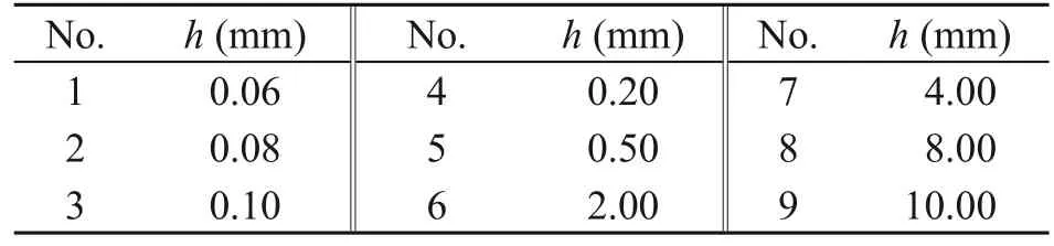
Table 2 Levels of clearance size h
We set the inner-wall diameter to 45 mm and adjusthby adjusting the diameter of the outer wall.The mapped mesh method is chosen to discretize the fluid domain and the curvature algorithm is chosen to control the mesh curvature (Fig.4).The average mesh quality of all models is about 0.9,and the orthogonal quality is 1.The fluid model is laminar flow,and all walls are treated as smooth non-slip walls.The inner wall temperature is set to 70 ℃.
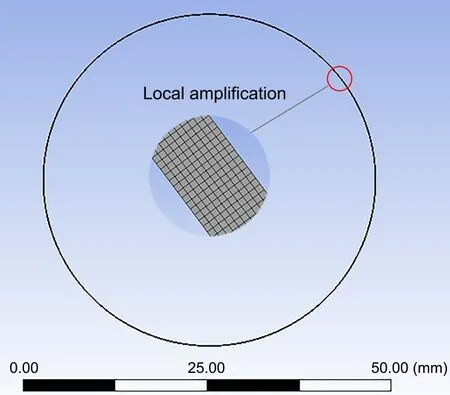
Fig.4 Discrete fluid domain with h=0.10 mm
The above models were solved to obtain the oil’s flow-and temperature-field distributions in the annular space (Fig.5).For observation,the upper,lower,left,and right regions of the result figures are intercepted separately for local enlargement.Fig.5a shows that the flow of oil is relatively fast on the left and right sides,and almost no flow occurs on the upper and lower sides of the channel.Further study shows that the temperature distribution is almost the same under different clearance sizes.
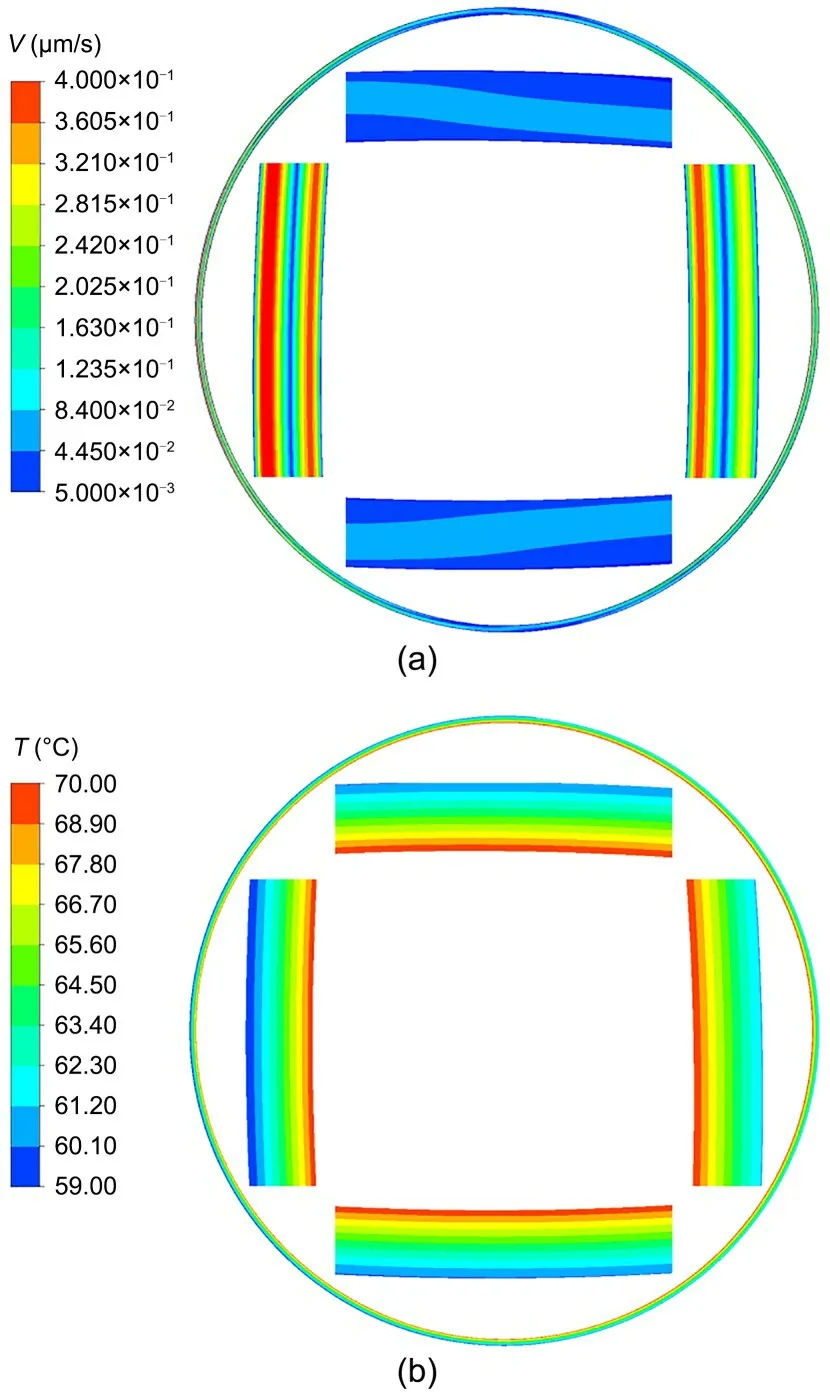
Fig.5 Flow field and temperature field with h=0.50 mm:(a) flow field;(b) temperature field.V: flow velocity of oil
Fig.6 shows the variation curves of oil average velocity and inner-wall drag torque with clearance sizeh.The oil velocity increases with the increase ofhfor both viscosity conditions: whenh<0.50 mm,the growth rate of velocity is larger and has no significant relationship with viscosity conditions;whenh>0.50 mm,the oil velocity with a constant viscosity is greater than that with a variable viscosity,and the velocity value tends gradually to stability.This is because the viscositytemperature effect lowers the velocity curve.Under the two viscosity conditions,the fluid-drag torque of oil acting on the inner wall first increases and then decreases,and finally tends to be stable with the increase ofh,with the peak value nearh=0.20 mm.This trend may be related to the fluid-velocity distribution at the inner wall.Referring to Fig.5,it can be seen that whenh<0.20 mm,there is a significant difference in the velocity of the oil near the inner wall on the left and right sides,and since the oil on both sides is flowing upward along the inner wall,the larger this velocity difference is,the larger the resultant torque is.Whenhincreases to more than 0.20 mm,the velocity difference at the inner walls of the left and right sides becomes smaller and smaller,so the drag torque gradually becomes smaller until it is stable.The changing trend of oil drag torque is the same under the two viscosity conditions,which indicates that the clearance effect has more influence on the drag torque than the viscosity-temperature effect does.
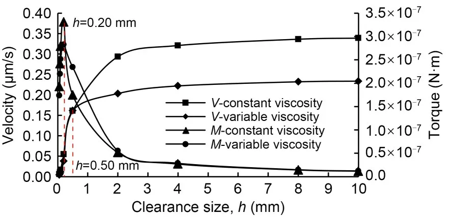
Fig.6 Variation curves of oil average velocity and drag torque M with clearance size h
3.2 Effect of roughness height
It is generally believed that the effect of surface roughness on laminar flow can be ignored;however,the flow channel in which the oil is located in the LFG is very narrow,and the minimum clearance is about 0.10 mm,so it is necessary to consider the effect of wall-roughness features on the oil flow.Annular geometry models with a rough inner wall were constructed according to the method proposed in Section 2.2,based on which the effect of roughness heightreon the microflow was analyzed.We set the outer-wall diameter at 49 mm with a clearance size of 2.00 mm,and assume the outer wall is smooth.The calculation case of nine levels is designed,and the specific scheme is shown in Table 3.
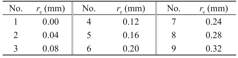
Table 3 Levels of roughness height re
The roughness densityεof all the inner walls constructed in this section is 0.57.The fluid domain is discretized by an automatic method and the mesh curvature is controlled by the curvature algorithm (Fig.7).All the walls have three boundary layers and the maximum face size is 0.1 mm.The average mesh quality of the models with smooth inner walls is 0.852 and the orthogonal mass is 0.998.The average mesh quality of the remaining models is greater than 0.7 and the orthogonal mass is greater than 0.95.The fluid model is laminar flow,and the inner and outer walls are treated as non-slip walls.The inner-wall temperature is set to 70 ℃ and the STD is set to 10 ℃.
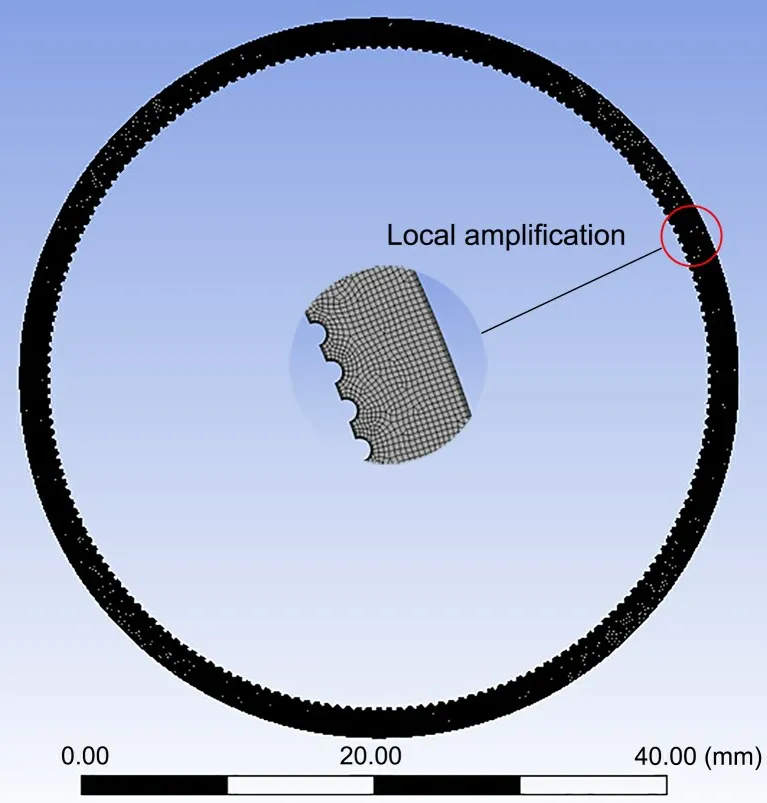
Fig.7 Discrete fluid domain with re=0.20 mm
The above models were solved to obtain the oil’s flow-and temperature-field distributions in the annular space (Fig.8).Fig.8a shows that no matter whether the inner wall is smooth or rough,the region of relatively high velocity for oil movement is located near the inner wall on the left and right sides.The difference is that when the wall surface is smooth,the velocity near the wall on the left and right sides is relatively continuous but when the wall is rough,the velocity near the wall is interrupted by the protrusions,and the larger velocity appears in the depressions.Fig.8b shows that the roughness height has no significant effect on the overall distribution of temperature.
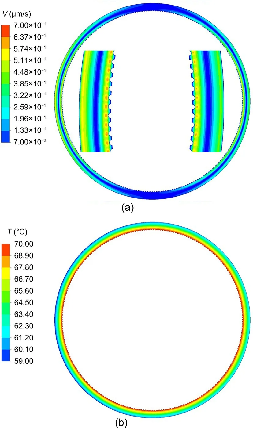
Fig.8 Flow field and temperature field with re=0.16 mm:(a) flow field;(b) temperature field
Fig.9 shows the variation curves of oil average velocity and inner-wall drag torque with roughness heightreunder two different viscosity conditions.The trend of the two curves is basically the same,but the viscosity-temperature effect significantly lowers the velocity curve.The variation curves of the torque under the two viscosity conditions largely coincide,indicating that the roughness height under microscale conditions affects the fluid-drag torque to a much greater extent than the viscosity-temperature effect.The overall trend of the drag torque is that the greater the roughness height,the greater the drag torque.This is because,as the roughness height increases,the obstruction effect of the roughness features on the oil becomes stronger,and the dynamic-pressure difference between the oil at the crest and trough of the roughness features increases,thus increasing the differential-pressure force,so the total drag torque becomes larger.
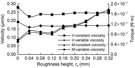
Fig.9 Variation curves of oil average velocity and drag torque with roughness height re
3.3 Effect of roughness density
In this section,the roughness features on the inner wall of the annular channel were constructed,and then the effect of roughness densityεon the dynamic characteristics of oil was investigated.The roughness heightreof the inner wall,the diameter of the outer wall,and the clearance sizehwere set as 0.04,49,and 2.00 mm,respectively.The calculation case of nine levels is designed,and the specific scheme is shown in Table 4.
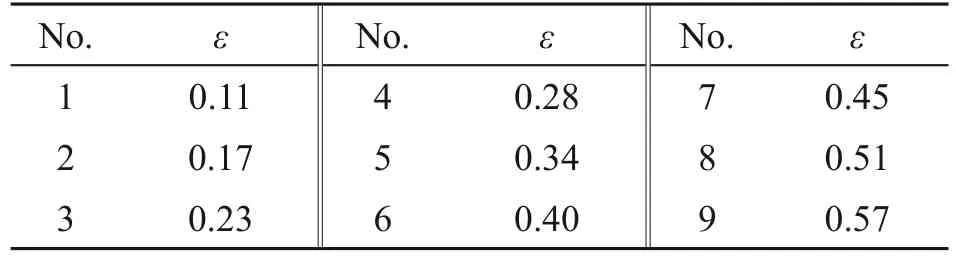
Table 4 Levels of roughness density ε
The geometric models established were discretized using the same method as in Section 3.2.The average mesh quality of all nine models is about 0.7 with the orthogonal quality greater than 0.9.The fluid model is laminar flow and the inner and outer walls are treated as no-slip walls.The temperature of the inner wall is 70 ℃,and the STD is 10 ℃.
The above models were solved to obtain the oil’s flow-and temperature-field distributions in the annular space (Fig.10).Fig.10a shows that the region with higher velocity is located at the left and right sides near the wall.For a given roughness height,as the roughness density increases,the fluid velocity gradually decreases,as shown in Fig.11.Since the thermal boundaries are the same and the structure of the fluid domain is highly similar,εhas no significant effect on the overall temperature distribution under steady-state conditions(Fig.10b).Due to the encryption of roughness features,the wall surface is “smoother”.Also,the roughness height is so small that the fluid flows smoothly from the top of the dense-roughness features,and thus the obstruction effect of the roughness features is weakened.
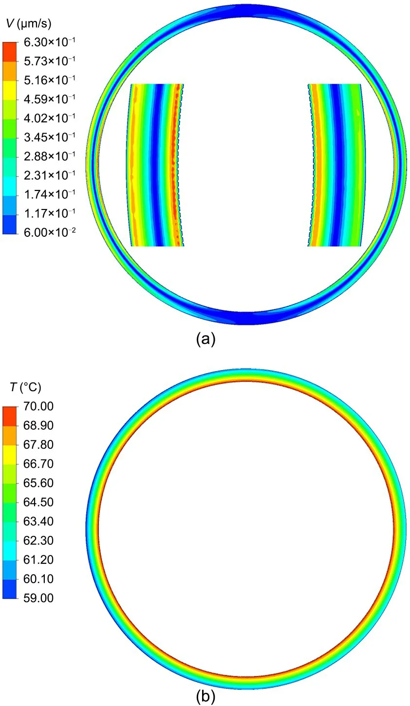
Fig.10 Flow field and temperature field with ε=0.34: (a) flow field;(b) temperature field
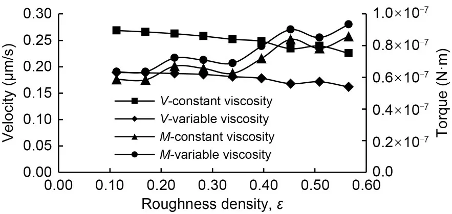
Fig.11 Variation curves of oil average velocity and drag torque with roughness density ε
Fig.11 shows the variation trends of oil average velocity and inner-wall drag torque at different roughness densities.It can be seen that the viscositytemperature effect pulls down the velocity curve and raises the torque curve to some extent.The variation curve of the drag torque shows that the torque increases approximately linearly with the increase ofε,indicating that the roughness density has a certain increasing effect on the oil drag torque,but the degree of its influence is smaller than that of the roughness height.
4 Conclusions
In this paper,2D flow-heat coupling models of the annular fluid domain inside LFGs were established.On this basis,the effects of annular flow-channel dimensions and surface roughness features on the fluid dynamics were analyzed.The following are the salient conclusions.
1.The clearance effect has a greater influence on the drag torque than the viscosity-temperature effect,and the torque first increases and then decreases,and finally tends to be stable with the increase in the clearance size.
2.The roughness of the channel walls significantly affects the oil dynamics,and the effect of roughness height on drag torque is greater than that of roughness density.
The study has shown that flow-channel dimensions and wall micromorphology have significant effects on the dynamics of microflow inside LFGs.This work can be useful in gaining insight into the oil-flow characteristics in the complex microchannels of LFGs,which may provide a reference for the precision manufacturing and accuracy improvement of gyro instruments.Future work will include the analysis of the impact of random roughness,according to the practical surface quality of the LFG.
Acknowledgments
This work is supported by the National Natural Science Foundation of China (No.U1937603).
Author contributions
Yaping ZHANG designed the research.Kai YANG and Boji LU processed the corresponding data.Yaping ZHANG wrote the first draft of the manuscript.Yanzhong WANG and Hao GAO revised and edited the final version.
Conflict of interest
Yanzhong WANG,Yaping ZHANG,Kai YANG,Boji LU,and Hao GAO declare that they have no conflict of interest.
 Journal of Zhejiang University-Science A(Applied Physics & Engineering)2023年12期
- Journal of Zhejiang University-Science A(Applied Physics & Engineering)的其它文章
- Key technologies and development trends of the soft abrasive flow finishing method
- Enhanced mixing efficiency for a novel 3D Tesla micromixer for Newtonian and non-Newtonian fluids
- Numerical modeling and experimental study of microstamping process for fabricating microchannels using thin sheets of titanium
- Solid-liquid flow characteristics and sticking-force analysis of valve-core fitting clearance
- Influence of adjacent shield tunneling construction on existing tunnel settlement: field monitoring and intelligent prediction
- GPU-accelerated vector-form particle-element method for 3D elastoplastic contact of structures