
Key technologies and development trends of the soft abrasive flow finishing method
2024-01-11 08:06YunfengTANYeshaNIWeixinXUYuanshenXIELinLIDapengTAN
Yunfeng TAN ,Yesha NI ,Weixin XU✉ ,Yuanshen XIE ,Lin LI✉ ,Dapeng TAN✉
1Key Lab of E&M,Ministry of Education & Zhejiang Province,Zhejiang University of Technology,Hangzhou 310014,China
2State Key Laboratory of Fluid Power and Mechatronic Systems,Zhejiang University,Hangzhou 310058,China
3Collaborative Innovation Center of High-end Laser Manufacturing Equipment,Zhejiang Province & Ministry of Education,Hangzhou 310014,China
Abstract: This paper reviews recent developments of the soft abrasive flow finishing (SAF) method in constraint space.The multiphase fluid dynamics modeling,material removal mechanism,auxiliary strengthening finishing techniques,and observation of surface impact effects by abrasive particles and cavitation bubbles are presented in brief.Development prospects and challenges are given for four aspects: thin-walled curved surfaces,biomedical functions,electronic information,and precise optical components.
Key words: Soft abrasive flow finishing (SAF);Dynamic modeling;Material removal mechanism;Processing optimization;Strengthening finishing control technology
1 Introduction
In aerospace,electronic information,biomedical,and laser manufacturing technologies,the surface quality of the functional materials used in various fields often determines the performance of the core devices.Many surface precision machining methods based on fluid abrasives have been proposed to meet the increasingly stringent surface processing quality requirements of various materials (Chen et al.,2020).The soft abrasive flow finishing (SAF) method has received wide attention because of its low processing cost,good adaptability to the surface of the workpiece,and fewer surface scratches (Ji et al.,2010a,2010b).Based on the fluid flow characteristics of the process,dynamic modeling,and related physical laws,the SAF method can be defined as follows.The working medium is created by using a loose,low-viscosity liquid medium wrap with micro-sized abrasive particles and micro-bubbles.The fluid abrasive particles squeeze,spray,or plough the surface of the workpieces in an open or closed processing cavity either alone or coupled with an auxiliary reinforcing physical field(Gao et al.,2015).
The SAF method differs from viscoelastic fluid processing methods such as extrusion,grinding,magnetorheological polishing,and high-pressure,highviscosity chemical-mechanical finishing processes(Kumar and Hiremath,2016;Zhang CH et al.,2020;Zhang P et al.,2020).The SAF method can present turbulent flow at lower speed and pressure,and remove a micro amount of the surface material of the workpiece with a micro force.Also,by using the turbulent wall effect,it can realize the target of a mirror surface finish on the workpiece,which has broad development prospects (Li et al.,2014).A schematic of SAF is shown in Fig.1.
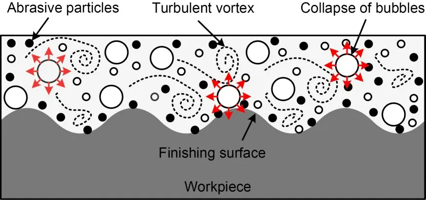
Fig.1 Schematic of SAF
Depending on the principle of the method,there are two main types of processing methods for SAF finishing: open processing and modular constrained processing.The most typical application of the open machining method is the abrasive fluid jet machining(AFJM) method.The constrained machining method uses low-viscosity fluids to envelope micro-size abrasive particles in modular restricted flow channels to impact the surface of the workpiece.
The AFJM is a localized corrosion and reinforcement manufacturing process adopted by the mineral extraction sector in the 1930s (Molitoris et al.,2016).In 1970,abrasive jet systems were marketed for a short period.Ceramic nozzles,which became mainstream in the industry,were used for cutting and cleaning (Hashish,1989;Li et al.,2023a,2023b).Fähnle et al.(1998) first proposed a unique processing technique that allows local shaping and polishing of optical surfaces with complex structures.Flow injection systems are used to direct a premixed filamentary flow at pressures below 0.6 MPa on the optical surface to significantly reduce the apparent roughness of the sample.This marked the beginning of research on the surface polishing of materials using the AFJM method.This technique is used to remove material from a workpiece using a jet fluid and abrasive particles under high-pressure conditions (Fig.2).The excess material is removed mainly by the abrasive particles,and the continuous water flow eliminates the thermal effects of the process,making it a suitable method for heat-sensitive materials (Nguyen and Wang,2019;Li et al.,2023c,2023d).
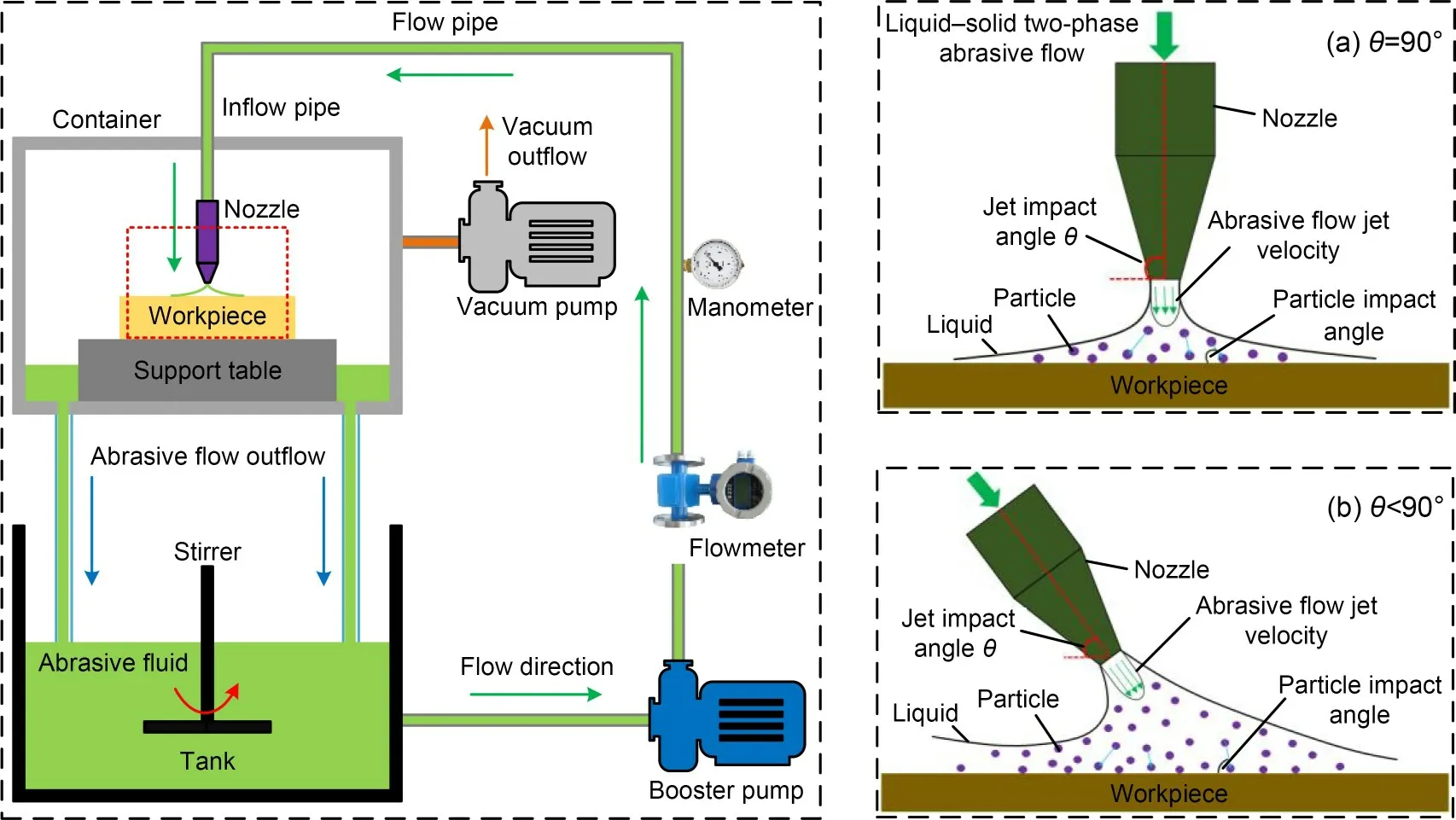
Fig.2 Schematic of AFJM
In mold manufacturing,special surfaces with complex structures and small scales are known as structural surfaces (Brinksmeier et al.,2004,2006).Ji et al.(2012a,2012b,2012c) presented a tool-free precision machining technique based on weakly viscous two-phase abrasive particle flow to reduce the surface roughness of the structured surface of a mold and to enhance the uniformity of the material surface texture.Ji et al.(2014) presented a gas-liquid-solid threephase abrasive flow processing method (GLSP) based on microbubble cavitation effects to improve the processing efficiency and uniformity of surface texture(Ge et al.,2018,2022;Li C et al.,2020;Li L et al.,2020a,2020b).The application of this method has been extended to workpieces made of hard-brittle materials such as monocrystalline wafers and optical glasses (Tan et al.,2016a,2016b,2017;Li YB et al.,2021).In these two SAF finishing methods,the processing medium is a weak viscous fluid containing abrasive particles or microbubbles that can be used to improve the efficiency of removal of material from the surface of the workpiece.
The SAF method with microbubbles mixed in the processing medium installs a constrained component near the machining surface of the workpiece(Fig.3).The abrasive flow enters the constrained machining space in turbulent form and achieves precise tolerances on the surface of the structure through particle-surface collision effects.
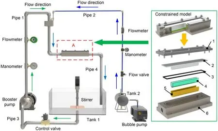
Fig.3 Schematic of the SAF method in the constrained model.1: cover plate;2: constrained component;3: seal ring;4:abrasive flow;5: workpiece;6: channel
Related studies have shown that the bubbles collapse under specific conditions such as severe pressure fluctuations,significant turbulence,and multiphase flow collisions (Lehr et al.,2002;Wang et al.,2003).The burst of a mass of bubbles produces numerous microjets,which can enhance the local fluid velocity and turbulence intensity (Zhang et al.,2001;Ni et al.,2012;Li L et al.,2021a,2021b).Due to the effect of bubble collapse,the dynamic energy of the particles is enhanced,and the motion becomes very disordered.Based on the Preston equation,Ji et al.(2011a,2011b) analyzed its application to SAF and modified the Preston coefficients so that it can meet the analytical requirements for SAF.Li et al.(2014) conducted a force analysis of the particle phase in the fluid,and analyzed the micro-cutting mechanism of the particles on the wall.According to the results,increasing the kinetic energy of particles in a fluid can enhance the removal efficiency of the material,while the uniformity of the material surface processing will also increase with the enhanced randomness of particle motion.
Many detailed reviews on AFJM have presented the problems and prospects of AFJM technology.After more than 10 years of development,research on SAF has generated a lot of knowledge,and the SAF method has become an important branch of abrasive flow processing (Ge JQ et al.,2021a,2021b,2021c;Ge M et al.,2021;Li et al.,2022).However,there are no comprehensive summaries of the constrained SAF method at present.In this paper we present the first systematic review of research results related to the SAF method as well as future research directions and challenges.The dynamics modeling of the soft processing fluid,material removal mechanism,auxiliary strengthening processing technique,and observation and control methods of abrasive flow wall effects are summarized.The method of observing and controlling the particle-wall effect during processing is unique compared with traditional abrasive flow processing methods.We hope this review can serve as a reference for future research on soft fluid finishing methods and technology development.
2 Dynamics modeling of SAF
After the SAF method was proposed,many fluid modeling methods were used to study the fluid velocity and pressure,abrasive motion,and wall processing contact effect (Zhang L et al.,2015,2018a,2018b;Tan et al.,2016a,2016b;Li J et al.,2017;Li JY et al.,2017;Li L et al.,2022).Ji et al.(2010a) applied the discrete phase model (DPM) method to establish a soft abrasive flow model for the precision machining of structural surfaces.Based on the results,the equations of motion of the abrasive grains in the Cartesian coordinate system were obtained.Ji et al.(2011a,2012a) presented a two-phase hydrodynamic model of SAF based on the level set method (LSM) topology structure transformation combined with the volume of fluid (VOF) approach.
The previous work clearly showed that the traditional modeling method of abrasive flow could hardly reflect the abrasive-wall contact effect,which is of great importance for fluid processing.To resolve this problem,a coupled computational fluid dynamics(CFD) and discrete element method (DEM) modeling method (CFD-DEM) of abrasive flow was proposed to obtain the abrasive-wall collision distribution and material removal characteristics (Zhu et al.,2008;Yang et al.,2014).This modeling method considers the particle volume and performs a detailed calculation of the particle-surface collision process,allowing more accurate modeling of particle motion.In addition,coupled ultrasonic,thermal,and magnetic multiphysical field models could provide a new direction for studying soft abrasive flow processing.
2.1 CFD-DEM coupling models
The CFD-DEM coupling model of abrasive flow includes mainly fluid phase description equations and discrete element analysis.The DEM model is a numerical analysis method used to analyze the contact force and motion distribution of discrete particles by calculating the motion pattern of a discontinuous particle population following fluid flow (Chu et al.,2009;Markauskas et al.,2017).The particles are treated as discrete phases,and the Newtonian control equations of motion are used to calculate their laws of motion.The equation of the force between the fluid and the abrasive,and parameters such as the volume fraction of the abrasive,are described,i.e.,the interaction calculation between the fluid phase and abrasive phase (Kotrocz et al.,2016;Li et al.,2019).
The coupled CFD-DEM solution performs data interaction by computing the interaction forces and porosity (α).In a mesh unit,the sum of porosity (α)and the particle’s volume fraction (αp) is equal to 1.The porosity can be acquired by computing the volume fraction of particles (αp).A box encloses the particles in a grid cell,and the number of sample points in the enclosing box is counted.The sample points located in the particles and grid cells are saved so that the volume fraction of the particles in the grid cells can be acquired from the relationship expressed in Eq.(1).
wherencis the sum of sample points located in the particles and grid cell,Nis the sum of the sample points located in the bounding box,andvcis the velocity of the particles.
2.2 Multi-physics coupling models of SAF
Based on the equations of hydromagnetics and Navier-Stokes,Li et al.(2022) presented a modeling method for coupling the gas-liquid-solid three-phase particle flow field with the magnetic field.The Maxwell stress tensor is applied to calculate the volume force of the electromagnetic field.The Navier-Stokes momentum conservation equation can be expressed by Eq.(2) (Fan et al.,2021):
whereFLis the contribution term of Lorentz force,ρis the fluid density,ηis the kinematic coefficient of viscosity,uis the velocity of the fluid,andPis the pressure.
As shown in Eq.(3),the contribution of the volume force at each point in the computational domain can be obtained by integrating the volume forcedFgenerated by magnetic fieldBand currentJin the entire flow channel region.Expanding the partial differential equation for the Lorentz force in the form of a vector product,we can obtain Eq.(4) for the volume force of the Lorentz force in each direction:
wherefvfis the volume force factor generated by magnetic field and current.Jx,Jy,andJzare the currents on thex,y,andzdirections,respectively.Bx,By,andBzare the magnetic fields on thex,y,andzdirections,respectively.
Coupling the electromagnetic model with the flow model is achieved by introducing the Lorentz force volume force at various points in the flow field.Reflecting the external product of the currentJand the magnetic field as the volume force in the law of conservation of momentum gives:
Han (2017) presented a fully developed fluid non-isothermal flow heat transfer model under the action of an electromagnetic field by coupling the electromagnetic,thermal,and fluid models.The heat transfer theory and characteristics were studied,providing a theoretical basis for the heat transfer optimization and control method.
The non-isothermal flow problem involves resolving the continuity,momentum,and energy-thermal equations on the basis of fluid dynamics,which can be obtained by coupling the fluid flow model and solid heat transfer model,as shown in Eq.(6):
whereIis the unit matrix,His the intensity of the magnetic field,Fis the resultant force of external forces,Cpis the specific heat capacity of the target material,qis the heat transfer rate,qris the heat flux,Tis the absolute temperature,τis the viscous stress tensor,θpis the coefficient of thermal expansion,μ0is the permeability constant in vacuum,μris the relative permeability of fluid,andQis the sum of the heat except for the viscous heat source.
The particle and bubble groups impact the wall at high speed under the influence of turbulence.The heat transfer coefficient during the process can be expressed by Eqs.(7) and (8):
wherehpandhgare the heat transfer coefficients of the particle and bubble group,respectively.vpiandνgiare the velocity vectors of the particle and gas phase in turbulent flow,respectively.kgandkcare the specific heat capacities of the gas and particle groups,respectively.cp,cg,andccare the specific heat capacities of the particle,gas,and particle groups,respectively.dpis the mean size of the particle,ρcis the density of the particle group,andρdis the density of the dispersed phase.ρp,ρg,andρlare the densities of the particle,gas,and liquid,respectively.tpis the impact time between the particle group and the boundary layer.lpis the grinding length between the particle group and boundary layer,andPris the Prandtl number.
SAF involves the micro-scale coupling mechanism of the multiphase flow interface,the mass transfer mechanism between the phases of the processing medium,and the quantitative analysis and theoretical modeling of the energy released by the micro-scale bubble collapse,which is an important research direction of the theoretical modeling of the SAF in the future.
3 Material removal mechanism of SAF
During SAF processing,the finishing medium ploughs the surface of the parts in a disorderly and random way under the effect of a turbulent flow field and bubble cavitation.Precision surface machining is achieved by the convex material micro-cutting effect on the surface of the parts (Tan et al.,2018a,2018b;Zhang LB et al.,2018).The material removal equation shows that the removal intensity of the soft abrasive flow on the surface of the parts is determined by the impact velocity of the processed abrasive particles and the pressure applied to the workpiece.Therefore,analyzing the cutting force of the abrasive particles and the cavitation impact of microbubbles under the turbulent flow environment is vital to elucidating the micro-cutting mechanism of multiphase abrasive flow near the wall.
3.1 Abrasive particle collision effect
Ji et al.(2011b) obtained the particle selection condition and empirical equations applicable to SAF by analyzing the Preston equation and its correction coefficients.Ji et al.(2012c) proposed a realizablek-εturbulent model to calculate the trajectory of particles within the boundary layer.The preliminary flow field distribution properties are established by analyzing the particle’s velocity before incidence,and the particle motion function is solved to calculate the velocity and incidence angle of the particle.
Ji et al.(2017b) established a surface contact analysis method based on a soft sphere model to achieve a quantitative analysis of normal and tangential collisions of abrasive particles with the wall.Fig.4 shows the contact process between the particlesiandj(jstands for particlejor wallj),whereβis the normal displacement andδis the tangential displacement.
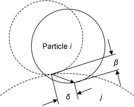
Fig.4 Schematic of the particle-wall contact process.Reprinted from (Ji et al.,2017b),Copyright 2017,with permission from Springer Nature
A soft sphere model is adopted to calculate the collision force.This model uses mainly an elastic coefficient and a damping coefficient to simplify the contact process and assumes that parameters stay the same in the contact process.
The soft sphere model sets springs and dampers between particlesiandj(Fig.5).The collision force can be decomposed into a normal collision force and a tangential collision force.The normal collision force(FNij) is given by
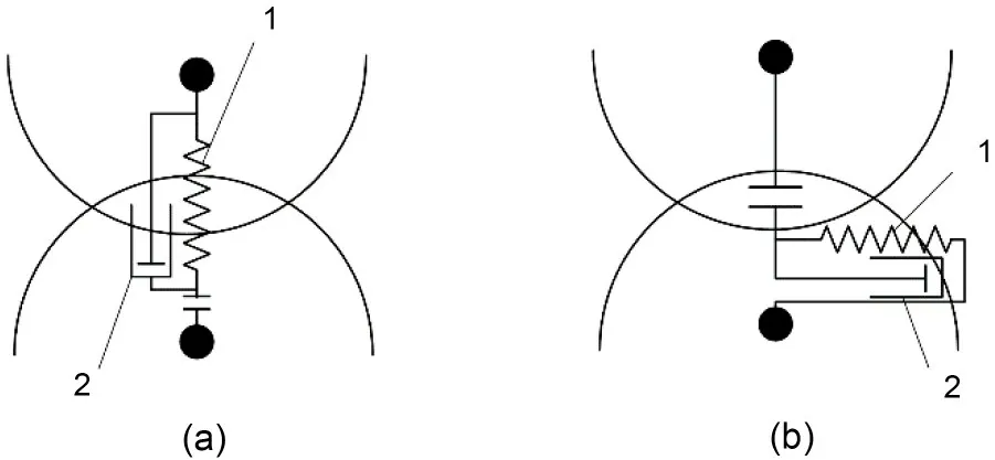
Fig.5 Soft sphere-based particle-wall contact model: (a)normal contact;(b) tangential contact.1: spring;2: damper.Reprinted from (Ji et al.,2017b),Copyright 2017,with permission from Springer Nature
whereGRis the relative velocity between particlesiandj,nis the unit vector from the sphere center of particleitoj,andkNandηNare the normal elastic coefficient and normal damping coefficient of particlei,respectively.The particle-wall contact process can be described by the soft sphere model (Fig.6).
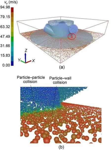
Fig.6 Axis view of macroscopic particle fluid: (a) global view;(b) partially enlarged view of region b.vp is the particle velocity.Reprinted from (Ji et al.,2017b),Copyright 2017,with permission from Springer Nature
3.2 Cavitation effect
Studies have shown that if a tiny bubble in a fluid collapses within a short period of time,the microjet produced by the collapse will release a tremendous amount of energy,which will be transformed into kinetic energy of the fluid in a small volume.This is known as cavitation shock (Lauterborn and Ohl,1997).Many studies have been conducted on cavitation shock mechanisms and adjustments (van Wijngaarden,2016;Sadeghi et al.,2018).The energy released by bubble cavitation can increase the kinetic energy of the surrounding tiny abrasive particles in the finishing medium,and improve the randomness of the direction of particle movement (Ji et al.,2019).Therefore,to improve the processing efficiency and surface quality of the workpiece,it is important to master the revolution mechanism and the methods regulating the impact of bubble cavitation in SAF (Zhao et al.,2022).
Zhao et al.(2020b) proposed a novel cavitation rotary abrasive flow polishing (CRAFP) method.The occurrence conditions and the intensity of cavitation effects were obtained (Fig.7).The cavitation numberσis defined by

Fig.7 Cavitation bubble content distribution at different tool inlet pressures: (a) 0 MPa;(b) 0.2 MPa;(c) 0.4 MPa;(d) 0.6 MPa;(e) 0.8 MPa;(f) 1.0 MPa.Reprinted from (Zhao et al.,2020b),Copyright 2020,with permission from Elsevier
wherePoandPiare the outlet and inlet pressures,respectively,andv0is the initial velocity of the processing medium in the inlet channel.A smallerσindicates a higher cavitation number and a stronger cavitation effect.According to the bubble cavitation theory(Mohseni-Mofidi et al.,2022),the pressure released from the cavitation effect can be expressed by
wherePmaxis the maximum pressure at the moment of bubble cavitation,P∞is the pressure of the outlet,andR0andRare the initial radius and the radius at the moment of bubble cavitation,respectively.
Pan et al.(2020) applied the Schnerr-Sauer model with good adaptability and convergence speed to numerically calculate the cavitation effect of microbubbles in multiphase fluid media (Fig.8).The corresponding control equations are shown in Eqs.(12)and (13).
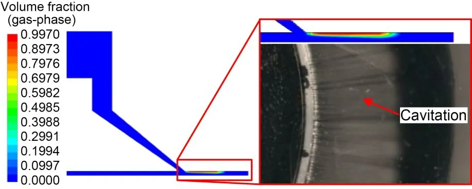
Fig.8 Cavitation volume fraction in the flow field.Reprinted from (Pan et al.,2020),Copyright 2020,with permission from Springer Nature
whereReandRcare mass transfer source terms connected to the growth and collapse of the vapor bubbles,respectively.FvapandFcondare the empirical calibration coefficients of evaporation and condensation,respectively.ρvandρfare the densities of vapor and fluid,respectively.ρmis the mixed phase density,φis the ratio of vapor,Rbis the bubble radius,Pis the hydrostatic pressure,andPvis the air pressure threshold.
Current SAF research focuses mainly on the mechanism of abrasive particle-wall interactions in the near-surface region and microbubble cavitation effects.However,variation in the surface texture of different materials,the direction of the motion of the abrasive particles relative to the raised peaks,the morphology of the raised peaks,and the fracture deformation of the raised peaks will greatly influence the removal effect of different material characteristics during soft abrasive flow processing (Tan et al.,2018a,2018b,2019a,2019b).Current research is lacking in these aspects which represent an important research direction.
4 Auxiliary strengthening processing technology
The polishing efficiency of SAF is low due to the limitation of the hydraulic diameter of the processing passages and the power of the abrasive flow driving pump (Zhang L et al.,2018a,2018b;Tan et al.,2020).In addition,because the viscous stress of the fluid near the wall region is much larger than the Reynolds stress,the turbulent boundary layer is prone to separation (Tan et al.,2014,2017).This reduces the fluid turbulence intensity and thus reduces the kinetic energy of the particles in the process of collision with the wall.Researchers have introduced many modifications to improve the turbulence intensity and abrasive processing capability in SAF polishing techniques,such as ultrasonic-assisted,magnetic-assisted,and rotary-assisted soft abrasive flow processing (Ge et al.,2022;Li et al.,2022;Mohseni-Mofidi et al.,2022).
4.1 Ultrasonic-assisted SAF method
The ultrasonic-assisted abrasive flow polishing method (UVAFP) is a composite polishing technique that combines ultrasonic vibration and abrasive flow in a turbulent state (Yu et al.,2019a;Wang et al.,2022).This polishing technology is ideal for hard,brittle,and difficult-to-machine surfaces and complex shapes.Therefore,it extends the process range of abrasive flow polishing technology and improves the efficiency and surface quality of the polishing process.Yu et al.(2019b) and Lu et al.(2020) have conducted extensive and in-depth research on UVAFP,combining ultrasonic vibration technology with various abrasive flow polishing technologies.They have proposed various ultrasonic-assisted abrasive flow polishing methods,which have achieved excellent results in the precision polishing of a variety of materials.Under the high-frequency impact of ultrasonic vibrations,the processing medium can finish the workpiece surface in three distinct ways.The first is the surface erosion effect of the workpiece under the influence of the hydrodynamic force of the processing medium.The second is through ultrasonic vibration directly driving the abrasive particles to impact the surface of the workpiece.The third way is via the ultrasonic vibrationinduced cavitation effect on the surface of the workpiece.
Ji et al.(2014) presented an ultrasound-enhanced ultra-precision abrasive flow finishing technique to address the issues of a long processing time and low efficiency of the SAF processing method,and established a coupled acoustic and flow field model.Li et al.(2019) presented an SAF finishing technique based on ultrasonic turbulence intensity enhancement effects.Results showed that the turbulence intensity of the abrasive flow reinforced by high-frequency ultrasonic vibration was more uniform,and the material removal rate during the finishing process was significantly improved.Ge JQ et al.(2021a) suggested an ultrasonic-assisted soft abrasive flow finishing(UA-SAF) technique to resolve the issue of the low polishing efficiency caused by the separation of turbulent layers in SAF (Fig.9).A CFD-DEM modeling approach and a dynamic mesh method are applied to describe the UA-SAF flow and periodic moving boundaries caused by ultrasonic vibrations (Fig.10)(Ge JQ et al.,2021c).The Archard model is adopted to calculate the effects of particle-wall erosion.The UA-SAF approach requires only 8 h to obtain a roughness (Ra) of less than 0.1 μm,and the ultimate roughness can reach around 0.018 μm,while the SAF method requires about 12 h to attain anRaof 0.1 μm.
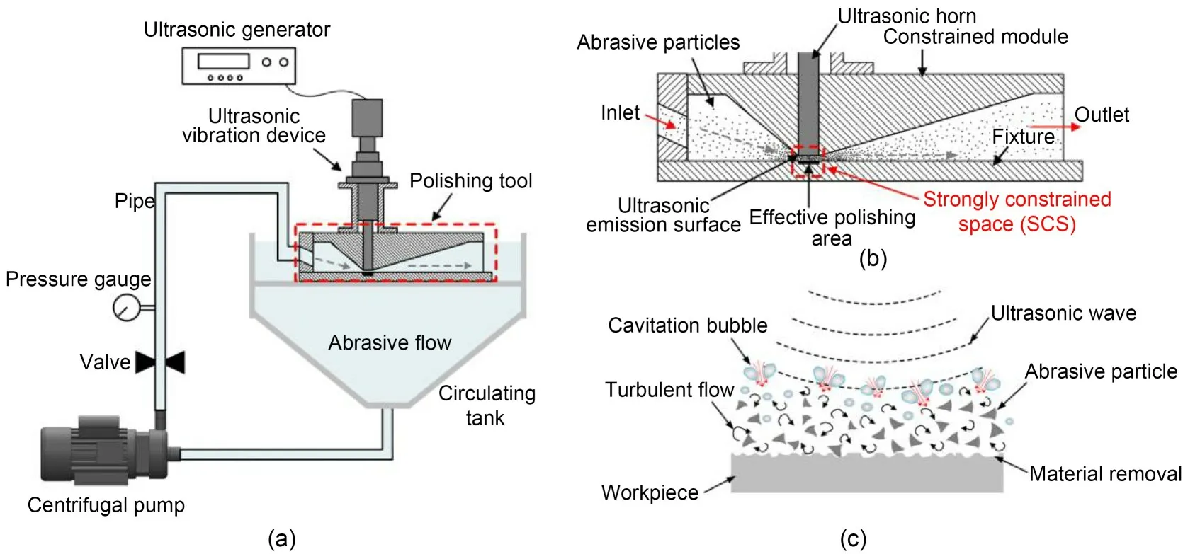
Fig.9 Schematic illustration of the ultrasonic-assisted SAF method: (a) overall structure diagram;(b) polishing tool;(c) polishing mechanism in the near-workpiece region.Reprinted from (Ge JQ et al.,2021a),Copyright 2021,with permission from Elsevier
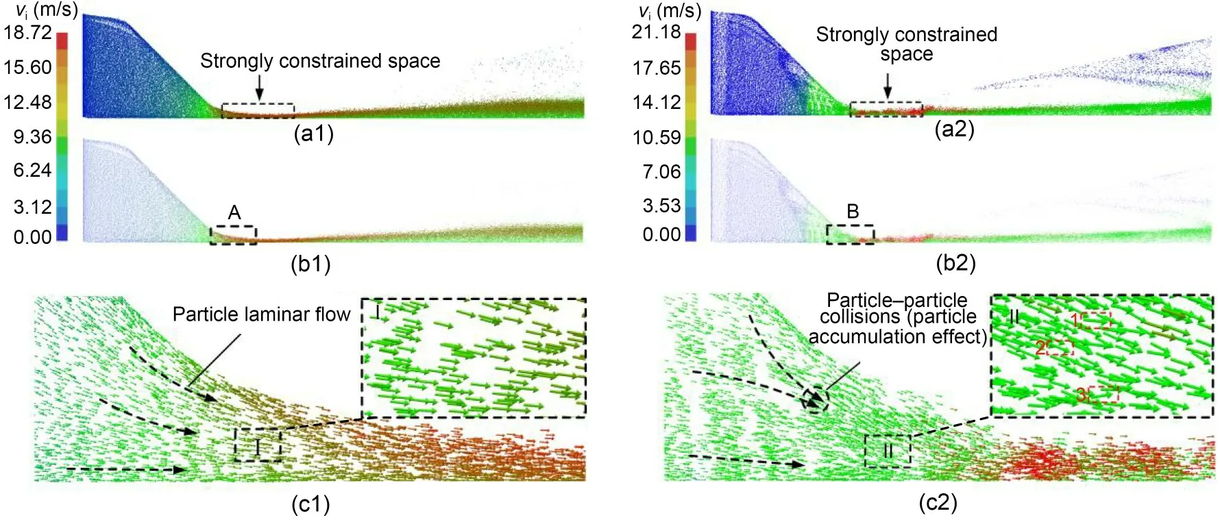
Fig.10 Characteristics of the particle motion state with/without ultrasonic vibration: (a1) particle distribution,without ultrasonic;(a2) particle distribution,with ultrasonic;(b1) velocity vector distribution,without ultrasonic;(b2) velocity vector distribution,with ultrasonic;(c1) partial enlarged view of the A part;(c2) partial enlarged view of the B part.vi is the particle velocity.Reprinted from (Ge JQ et al.,2021c),Copyright 2021,with permission from Springer Nature
Currently,ultrasonic energy is applied to the flow field to calculate the flow field characteristics and the influence of the flow field on particle motion.There is a lack of in-depth research on the effect of the collapse of micro-scale bubble particles in fluid media under ultrasonic action.
4.2 Magnetic-assisted SAF method
Magnetic-assisted finishing is a relatively new approach that has been proven to be a cost-effective machining method (Peruri and Chaganti,2019).The magnetic-assisted method provides excellent surface quality and machining accuracy regardless of the hardness of the workpiece being machined.Also,it does not introduce additional residual stresses to the processed surface.Under the action of viscous force,the fluid pulsation velocity gradually decreases in the near-wall layer,and laminar flow is dominant (Yin et al.,2020).The soft abrasive flow can be applied to act on the inner wall of the pipe and the edge of the blade,but the abrasive particle processing efficiency near the wall surface is insufficient.The use of an external magnetic force to apply an auxiliary driving force to soft abrasive flow particles to improve the cutting ability of abrasive flow particles on the surface of the workpiece could be a hugely significant advance.Fig.11 depicts a schematic diagram of the magnetically assisted SAF method.
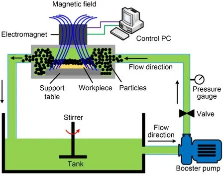
Fig.11 Schematic of the magnetic-assisted SAF method
Research on the multiple physical field coupling modeling of the magnetic field and multiphase abrasive flow field is critical.Simulations of magnetorheological fluids (MRF) can usually be divided into three groups according to how the interface between the carrier fluid and the particles is resolved: one-way coupling,two-way coupling,and direct numerical simulation (DNS).Lagger et al.(2014) investigated the development and fragmentation of magnetic particle agglomerates in MRF under shear stress from the perspective of magnetic field strength and particle volume fraction using the DEM method.Ke et al.(2017) proposed a system for solving the Navier-Stokes equations using the lattice Boltzmann method(LBM) and exchanging momentum between the fluid and discrete particles using the immersion boundary technique (IBM).Mohseni-Mofidi et al.(2022) investigated the effect of an applied magnetic field on SAF performance using smoothed particle hydrodynamics(SPH) format discrete fluids,particles,and surfaces to treat the multiphysics field of the control equations consistently for each phase (Fig.12).

Fig.12 Surface erosion simulation using circular grains for a magnetic gradient of 500 T/m at times 0 ms (a),2.5 ms (b),and 5.0 ms (c),and for a magnetic gradient of 1000 T/m at times 0.5 ms (d),2.5 ms (e),and 5.0 ms (f).Reprinted from(Mohseni-Mofidi et al.,2022),Copyright 2022,with permission from Elsevier
The analysis of flow field characteristics and particle motion under magnetic field coupling is a direction that is worth exploring in the future (Tan et al.,2013).The use of a magnetic field to guide the direction of particle motion can achieve fixed-point machining of the machined surface,which has unique advantages (Tan et al.,2013;Tan and Zhang,2014).Relevant theoretical modeling and experimental research need to continue.
4.3 Rotary-assisted SAF method
The SAF machining method yields spatially constrained flow channels by setting the constraint module on the workpiece surface.The abrasive flow in a turbulent state passes through the restricted flow passages at high speed,pushing the internal abrasive particles in a disorderly motion.This generates a microforce and micro-cutting effect on the surface of the workpiece,thereby achieving a high-precision polishing effect.Therefore,to improve the machining efficiency and the uniformity of the machined surface it is important to improve the disorderly motion of abrasive particles and the turbulence intensity of abrasive particle flow on the workpiece surface.A vortex in the state of high-speed turbulence can significantly improve the disorder of particle motion (Tan et al.,2019a;Yin et al.,2022a,2022b).Therefore,rotationassisted SAF methods formed by external mechanical driving forces or flow channel structures have been proposed and studied extensively by many scholars.
Walia et al.(2006) proposed a centrifugal forceassisted abrasive flow machining (CFAAFM) method in which a rotating rod exerts a centrifugal force on an abrasive suspension to increase the surface finish within a cylindrical workpiece.Yuan et al.(2016) developed a spiral-rotating abrasive flow polishing technique to explore the precision polishing of the inner surface of 6061 aluminum alloy barrels.The material removal rate increases as the rotation speed increases due to the greater kinetic energy introduced by the rotation of the constraint module (Fig.13).Ji et al.(2017a) introduced a gas-liquid-solid three-phase rotary abrasive flow machining technique (RGLSP) to explore the effect of bubble cavitation on processing efficiency.Zhao et al.(2020a,2021) introduced a novel soft abrasive rotational flow (SARF) finishing method to achieve low surface damage and ultra-smooth,uniform finishing of large-size K9 optical glass surfaces,achieving a final surface roughness ofRa=4.51 nm.A comparative analysis of research results of various auxiliary processing methods is shown in Table 1.
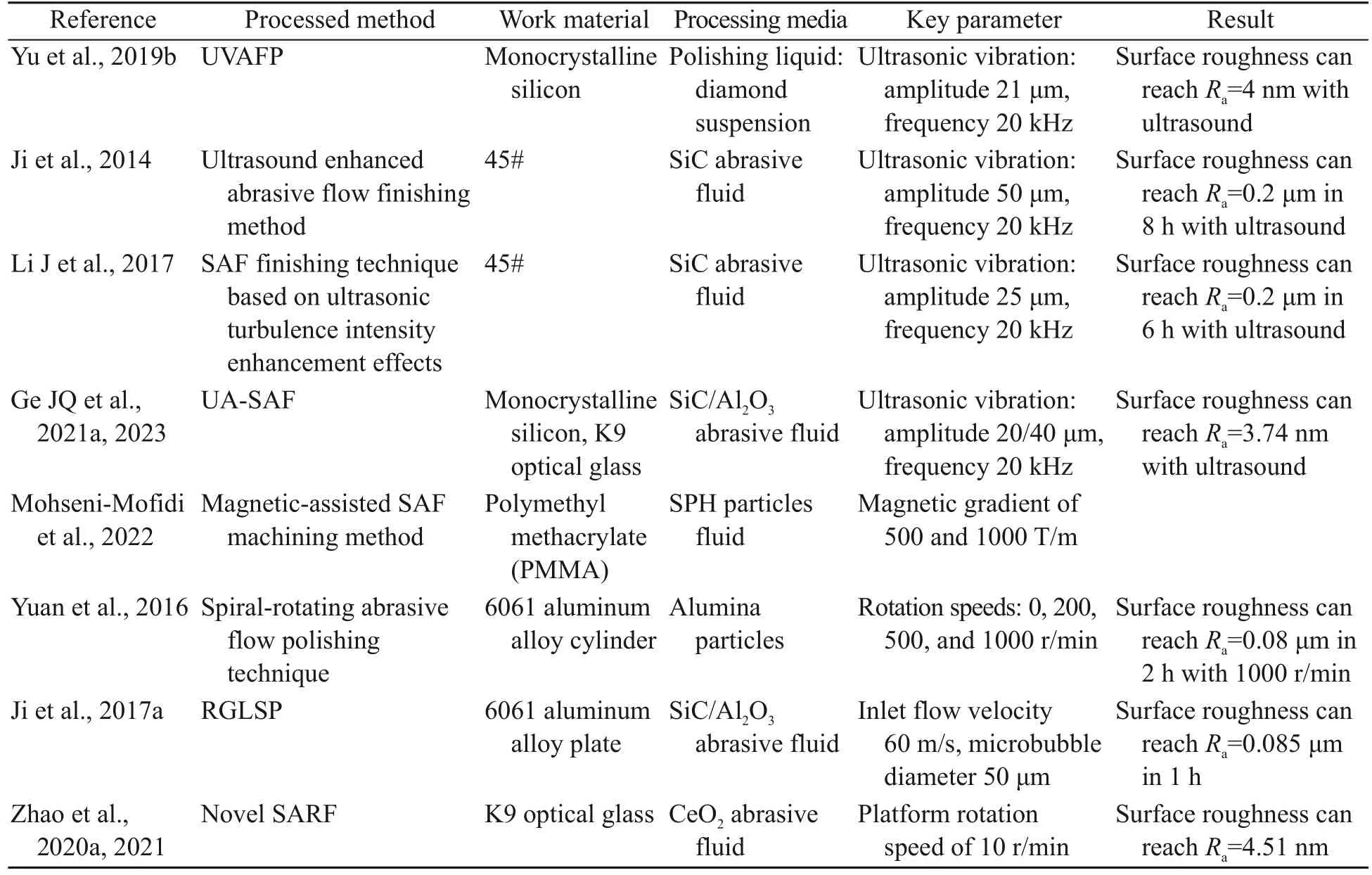
Table 1 Comparative analysis of research results of various auxiliary processing methods
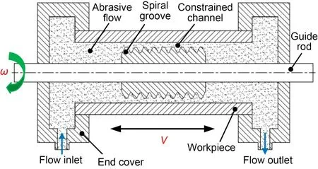
Fig.13 Schematic illustration of the spiral-rotating abrasive flow polishing method
Limited by the power of the pump and the structure of the key rotating auxiliary machining parts,the processing efficiency of this method is not high at present,and the applicable workpiece structure also has many limitations,which need to be further explored.
5 Methods for observing and controlling the wall contact effect
The SAF machining process involves the movement of a multiphase fluid processing medium in a finite flow passage space (Yin et al.,2022b).The cavitation effect strengthens the turbulent intensity of fluid and makes abrasive flow polish the workpiece surface with a more disordered turbulent wall effect.Measurement of the flow field under complex motion is the most direct and effective way to study the motion pattern of the flow fluid processing medium(Zheng et al.,2021;Wang JX et al.,2023).The accuracy of fluid processing medium modeling,the effectiveness of the processing medium-wall contact effect,and the cavitation-wall effect can be demonstrated by the velocity vector and vortex distribution of the fluid medium flow field.The rapid change of velocity vectors and vortices in high-speed turbulent rotating flow fields requires a measurement technique with quick dynamic response and high accuracy.
Particle image velocimetry (PIV) is a typical non-contact and high-precision measurement method for particle motion observation in a flow field.PIV technology is a full-flow field observation technology developed in the 1980s (Wang et al.,2020;Yu et al.,2020).This method lights the measurement region of the flow field with laser-pulsed sheet light and uses a camera to repeatedly record the location of tracer particles in the processing medium flow field.After solving and analyzing the trajectory of tracer particles using an image processing technique,the velocity vector distribution of the processing medium flow field is determined.Based on the surface material removal mechanism of the SAF machining method,the impact effect of the processing particle medium on the material surface and the wall erosion effect of cavitation bubbles are observed online using PIV technology.Then the precise quantitative calculation of the processing effect of soft abrasive flow can be carried out,which has significant scientific value and engineering significance (Wang T et al.,2023).
5.1 Observation of particle-wall contact effect
Ji et al.(2012b) applied the PIV analysis method to study the motion pattern and wall collision effect of the processing particle group in the finite flow passage space.The results showed that the whole trajectory of the abrasive particle group from the beginning of the collision to the deviation from the wall is roughly in a vortex state,and there is inter-particle interaction during this period.Li C et al.(2012,2020)reported a PIV experiment in which particle motion trails of SAF were generated.The particle tracking analysis technique was applied to examine particle motion (Fig.14).The results revealed that the tracer particles collide with the surface and reflect angularly,followed by irregular motion with SAF.
5.2 Observation of cavitation-wall contact effect
Ji et al.(2014) presented an ultrasonic-enhanced soft abrasive flow machining method and established a PIV observation platform.They found that there are numerous cavitation bubbles growing and hitting the surface of the wall continuously.The processing time can be reduced to a certain extent,and the processing efficiency can be improved by applying ultrasonics to SAF.Ge JQ et al.(2021b) conducted a PIV observation experiment for gas-liquid-solid three-phase abrasive flow machining.The results showed that the average velocity can be increased from 12.5-13.5 m/s to 15.0-17.0 m/s by injecting microbubbles,and the maximum velocity value can be shown to approach more than 20.0 m/s (Fig.15).Pan et al.(2020) developed a PIV observation and measurement experiment platform to obtain images of the bubble group cavitation effect under different experimental conditions.The maximum velocity of the fluid processing medium in the constrained finishing region of the SAF tool was 22.8 m/s,while the maximum movement velocity of the fluid medium after cavitation in the constrained finishing region of the cavitation soft abrasive flow finishing (CSAF) tool was 46.2 m/s.

Fig.15 Observation of near-wall flow field after bubble collapse: (a) near-wall flow field;(b) near-wall velocity vector distribution;(c) near-wall vorticity distribution.Reprinted from (Ge JQ et al.,2021b),Copyright 2021,with permission from Elsevier
At present,most PIV research methods use 2D scales for quantitative analysis of abrasive particles or bubble particles (Zheng et al.,2023a,2023b).However,the abrasive flow medium is a complex fluid motion in a 3D physical space in SAF.The PIV observation method at a 3D scale should be used to further explore the interactions between the particle and wall and between the particle and bubbles.
6 Development and application prospect of SAF
Modern science and technology are developing rapidly,and the surface accuracy requirements of various precision components are becoming more and more stringent (Wang et al.,2021).The core components often determine the overall performance of the instruments and equipment,such as the thin-wall curved aerospace components,biomedical functional components,electronic information,and optics components (Lyu et al.,2022,2023).The SAF surface finishing method has good prospects for development and application in the future because of its technical advantages such as good adaptability of processing structure,low processing stress,high precision of material surface removal,energy savings,and environmental protection.
6.1 Thin-walled curved component finishing
Thin-walled curved components are widely applied in the aerospace industry due to their excellent physical and mechanical properties of light weight and high strength.However,they are prone to deformation and brittle collapse during processing due to their complex form of force.Traditional machining methods often make it challenging to achieve high surface accuracy while ensuring the accuracy of the surface profile.For example,an aircraft blade is a typical thin-walled curved workpiece.Its edge radius of curvature is very small,and a small compressor blade can even reach theRa=0.1 mm level,which makes the finishing process very difficult.
The SAF method is a relatively efficient surface processing method because it creates good flexible contact with the surface and has special technical advantages for the processing of complex structural surfaces.Li JY et al.(2017) studied the influence of the abrasive flow polishing temperature on the quality of engine nozzles at the mesoscopic scale.The findings indicate that the highest-grade abrasive flow polishing may be achieved between 300 and 310 K.Li YB et al.(2021) proposed a thin-walled curved surface liquid metal abrasive flow ultra-precision finishing method based on abrasive particles.This was a useful attempt to solve the problems of the thin-walled curved surface of titanium alloy (Fig.16).The results showed that the processing uniformity of each area of the workpiece surface was improved substantially.The roughness of the processing region reached 20.3 nm.This study offers a theoretical and experimental reference for exploring the processing mechanism of liquid metal abrasive flow.
6.2 Biomedical functional component finishing
Because of their high biocompatibility,titanium alloy materials have a wide range of applications in biomedical fields,such as the manufacture of artificial hip and knee joints,dental implants,and joint plates.Their performance is highly dependent on the surface morphology in practical applications.Artificial parts such as hip and knee joints often move relative to each other due to limb movement after implantation.Rougher surfaces may increase friction between multiple joint surfaces,thereby reducing the service life of the artificial joint components in the implanted human limb and the normal movement of the limb.Therefore,it is essential to polish these machined artificial parts to a high surface quality to enhance the user experience and normal life of the patient receiving the artificial joint.Due to the structural characteristics of the curved surfaces of most artificial joints,such as large changes in curvature and many tiny structures,it is difficult to polish them accurately using conventional machining techniques.The SAF method is the most promising option to meet the specific needs of high-precision processing of artificial joint surfaces due to its good adaptability to complex surfaces.
Zhang et al.(2015) presented a partially covered constrained complex surface turbulent precision finishing method to solve the processing issues associated with the complex surfaces of artificial joints of titaniferous alloy material.The results of the trial demonstrated the efficiency and viability of this strategy.Zhang et al.(2017) presented a gas compensationbased abrasive flow (GCAF) finishing method to improve the uniformity and efficiency of complicated titanium alloy surfaces (Fig.17).The results showed that the method can effectively improve the processing efficiency and workpiece surface texture processing uniformity.The average surface roughness of the processing region reachedRa=0.3 μm,and the surface morphology approached less than 10 μm (Fig.18).
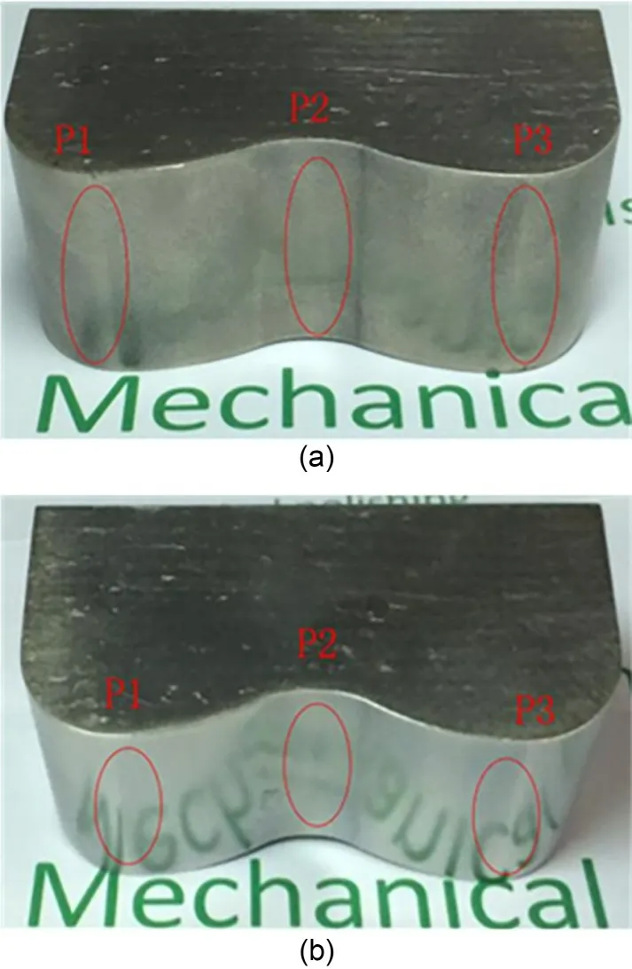
Fig.18 Effects of using the proposed GCAF processing method on an artificial joint base entity: (a) before processing;(b) after 20-h processing.Reprinted from (Ge JQ et al.,2021b),Copyright 2021,with permission from Elsevier
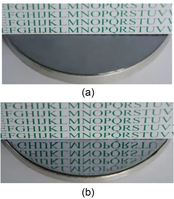
Fig.19 A surface processed by the GLSP method: (a) before processing;(b) after processing.Reprinted from (Ge et al.,2018),Copyright 2017,with permission from Springer Nature
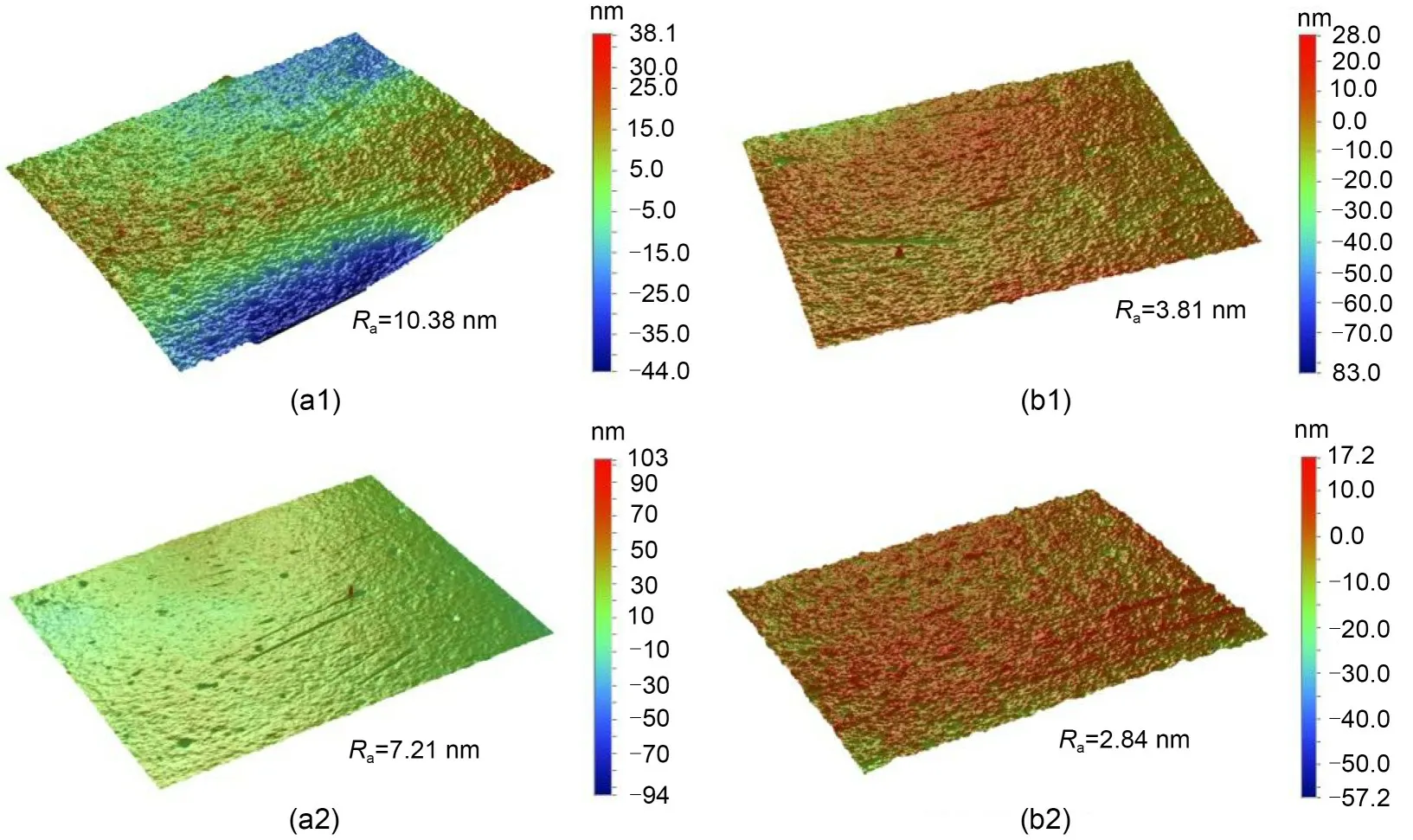
Fig.20 Surface topography data obtained by the SAF (a1 and a2) and GLSP (b1 and b2) methods.Reprinted from(Ge et al.,2018),Copyright 2017,with permission from Springer Nature
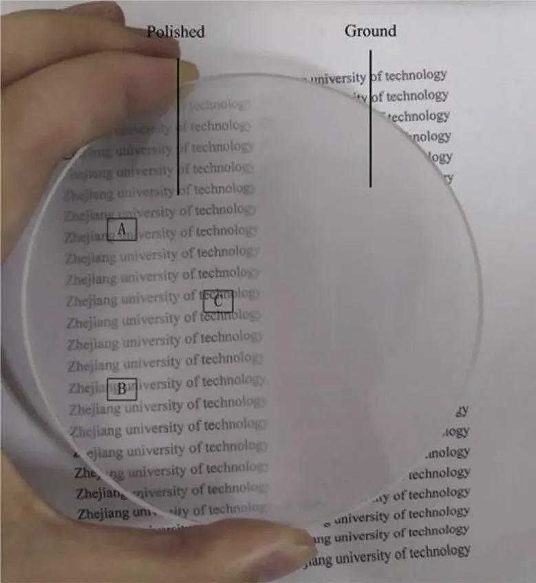
Fig.21 Overall image of a workpiece surface processed using the SARF polishing method.Reprinted from (Zhao et al.,2020a),Copyright 2020,with permission from Elsevier
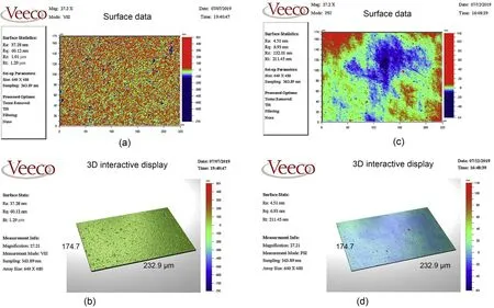
Fig.22 Measurement of the surface roughness by: (a) grinding process;(b) SARF process;(c) grinding process and measurement of the surface 3D plot;(d) SARF process and measurement of the surface 3D plot.Reprinted from (Zhao et al.,2020a),Copyright 2020,with permission from Elsevier
6.3 Electronic information component finishing
Electronic information materials include the socalled hard and brittle materials.They serve as the main components of precision measurement systems such as masks and substrates for microfluidic chips(Lyu et al.,2023).The degree of accuracy of the workpiece surface has a significant impact on the performance of the precision measuring equipment.As measurement accuracy standards continue to improve,higher demands are being placed on the surface quality of critical components.Compared with the conventional tool-contact polishing approach,the fluid machining method can mitigate the over-impact effect produced by big particles or contaminants with its high degree of flexibility.As a result,scratches and surface damage may be effectively eliminated.
For silicon wafers,many researchers have experimented with SAF technology for surface polishing.Ge et al.(2018) proposed the GLSP method for monocrystalline silicon material.The method enhances the processing ability of abrasive particles by introducing the microbubble collapse effect.The energy released by bubble cavitation in the confined space increases the processing efficiency by 50%,and the surface roughness of the material in the confined processing region can reachRa=2.84 nm (Figs.19 and 20).
6.4 Optics component finishing
Precision optical glass occupies an important position in modern precision instruments and large equipment.The surface processing of precision optical glass is an important research direction for SAF.Many scholars have carried out in-depth studies and accumulated informative results.
Zhao et al.(2020a) proposed the SARF polishing method,which enables high-speed rotational processing of the abrasive fluid processing medium between the processing tool and the workpiece.Experiments showed that this processing method can significantly reduce the damage on the machined surface of largesize K9 optical glass,and also improve the flatness and uniformity of the machined surface.After 1.5 h of machining,the surface roughness reachedRa=4.51 nm,which was 87.9% lower than the original roughness(Figs.21 and 22).
Aiming to precisely polish glass-based microfluidic chips,Ge et al.(2022) proposed an ultrasonic coupled abrasive jet polishing (UC-AJP) method.The UC-AJP polishing system was developed to improve the efficiency of AFJM,and comparative polishing experiments with various amplitudes were carried out.The polishing efficiency was effectively improved through the pulse effect.The roughnessRareached 0.049 μm after polishing using the UC-AJP method,with an amplitude of 20 μm.
SAF has gradually developed into an important branch of precision machining methods for finishing the surface of difficult-to-machine materials (Tan et al.,2023).However,previous studies have lacked complete sets of processing equipment,and there have been few attempts to put the processed products into practical use (Wang et al.,2021).In future,the research and development of special equipment for SAF and the practical testing and application of processed products should be strengthened.
7 Conclusions
Abrasive flow machining (AFM) technology has been developing for 60 years,and with the increasing demand for precision machining,new surface machining technologies are being explored.The SAF method is becoming a new branch of abrasive flow surface finishing technology.Numerous research results have been published in recent years,providing a new direction of exploration for achieving precision surface machining of many difficult-to-machine materials.More in-depth research is needed in the following areas:
(1) The fluid phase of the multiphase processing medium is a combination of gas and liquid phases,while the solid phase consists of discrete abrasive particles.The kinetic movement mechanism and evolutionary pattern are very complex.In SAF processing,the accurate modeling and numerical solution of the fluid flow characteristics,processing mechanism,energy released by the cavitation effect,and particlemicrobubble interaction in a turbulent flow state will be important aspects of subsequent research.
(2) To improve the processing efficiency of SAF and further clarify the material removal mechanism of abrasive particles in various processing situations,more detailed research is needed on the research methods used in various auxiliary energy fields and to explore new technological directions.
(3) Combined with the processing theory of the SAF method,the processing effect can be improved by more than one order of magnitude by changing the type and size of the abrasive material and developing new processing technology,which can be further applied to the ultra-precision polishing of hard and brittle material parts,such as those made of sapphire or quartz.
(4) Research is needed to develop new processes and equipment based on the SAF method,which can offer new solutions to bottleneck technical problems in the manufacture of key components in the fields of aerospace,high-end chips,and precision optics.
Acknowledgments
This work is supported by the National Natural Science Foundation of China (Nos.52175124 and 52305139),the Natural Science Foundation of Zhejiang Province (Nos.LZ21E050003,LY17E050004,and LQ23E050017),the Zhejiang Provincial Postdoctoral Merit-Based Funding Project(No.ZJ2022068),and the Open Foundation of the State Key Laboratory of Fluid Power and Mechatronic Systems (No.GZKF-202125),China.
Author contributions
All authors contributed to the study’s conception and design.Conceptualization,methodology,and writing review were performed by Dapeng TAN.The investigation,validation,and writing of the original draft were performed by Yunfeng TAN.Software and visualization were performed by Yesha NI.Data curation and formal analysis were performed by Weixin XU and Yuanshen XIE.Writing review and editing were performed by Lin LI.All authors read and approved the final manuscript.
Conflict of interest
Yunfeng TAN,Yesha NI,Weixin XU,Yuanshen XIE,Lin LI,and Dapeng TAN declare that they have no conflict of interest.
 Journal of Zhejiang University-Science A(Applied Physics & Engineering)2023年12期
- Journal of Zhejiang University-Science A(Applied Physics & Engineering)的其它文章
- Enhanced mixing efficiency for a novel 3D Tesla micromixer for Newtonian and non-Newtonian fluids
- Numerical modeling and experimental study of microstamping process for fabricating microchannels using thin sheets of titanium
- Solid-liquid flow characteristics and sticking-force analysis of valve-core fitting clearance
- Influence of adjacent shield tunneling construction on existing tunnel settlement: field monitoring and intelligent prediction
- GPU-accelerated vector-form particle-element method for 3D elastoplastic contact of structures
- Dynamics of buoyancy-driven microflow in a narrow annular space