
Numerical modeling and experimental study of microstamping process for fabricating microchannels using thin sheets of titanium
2024-01-11 08:07WenzeMAOYanchengWANGDeqingMEILingfengXUANCaiyingZHOU
Wenze MAO ,Yancheng WANG✉ ,Deqing MEI ,Lingfeng XUAN ,Caiying ZHOU
1State Key Laboratory of Fluid Power and Mechatronic Systems,School of Mechanical Engineering,Zhejiang University,Hangzhou 310058,China
2Key Laboratory of Advanced Manufacturing Technology of Zhejiang Province,School of Mechanical Engineering,Zhejiang University,Hangzhou 310058,China
Abstract: Ultra-thin sheets of titanium for fabricating microchannels have been used in fuel cells due to their good corrosion resistance and high strength-weight ratio.This paper presents a constitutive model for studying the anisotropy effects of pure titanium (CP-Ti) sheet on the springback behavior and forming properties during the microstamping process.Thin sheets of CP-Ti specimens with different orientations were examined using uniaxial tensile tests to assess the effects of anisotropy on their mechanical properties.Then an anisotropic constitutive model considering the off-axis elastic modulus was developed based on orthotropic elasticity and Hill’s yield criterion.Numerical modeling and simulation of the microstamping process for fabricating multi-channel structures were performed.The effects of anisotropy on the springback of multi-channels were investigated and compared with experimental results;the effects of tool dimension parameters on the formability of microchannel structures were also analyzed.The results showed that the anisotropy of thin titanium sheets causes various degrees of forming loads and springback in the microstamping of microchannels at different orientations.This study accurately predicts the springback of thin titanium sheet used to fabricate microchannel structures and is a good guide to the formation of such structures.
Key words: Titanium sheets;Microstamping;Anisotropy;Constitutive model;Springback
1 Introduction
With the advance of manufacturing technologies,micro-components and products have been widely used in electronic devices (Feng et al.,2022),biomedicine (Srinivasan et al.,2019),and new energy vehicles (Peng et al.,2014) due to their small size,light weight,and ease of mass production (Qin,2006).Microchannels,as one of the most used products,have been applied in microreactors (Hwang et al.,2011) and heat exchangers (Zhou et al.,2018) for clean energy products.For example,metal-based bipolar plates are the key component of proton exchange membrane fuel cells (PEMFCs),and use fabricated microchannels on thin sheets of metal to separate and introduce the reaction gas and to collect the conduction current (Song et al.,2020).There are several types of fabrication process for microchannel structures,such as microstamping (Subramonian et al.,2013),rubber pad microforming (Elyasi et al.,2017),and hydroforming (Xu et al.,2019),of which microstamping is widely used due to its advantages of high precision,high production efficiency,and generally low cost (Zhou et al.,2010;Winter et al.,2021;Si et al.,2022).
Lightweight materials like titanium alloys and aluminum alloys have been used to fabricate microchannel structures,although they usually have low elongation rate and produce high springback during forming.Karacan et al.(2020) investigated the use of a microstamping process to fabricate titanium bipolar plates,and compared it with stainless steel.The results showed that both stainless steel and titanium alloy bipolar plates can be used to fabricate microchannels with depth of 0.36 mm but the titanium ones have lower weight,better corrosion resistance,and greater strength-weight ratio (Kim et al.,2011;Won et al.,2021;Boban and Ahmed,2022).Mahabunphachai et al.(2010) used experimental tests to compare the forming properties of pure titanium (CP-Ti) and stainless steel.CP-Ti was found to have a smaller forming depth at a forming pressure of 200 kN and stamping speed of 1.0 mm/s.Badr et al.(2016) demonstrated that titanium alloy sheets had an elongation of no more than 15%,and that they might not be usable to fabricate microchannels with high depth.Further,the low elastic modulus and high elastic recovery of titanium sheet would generate greater springback behavior and affect the fabrication accuracy (Liu et al.,2011).In addition,titanium and its alloys have been demonstrated with high anisotropic properties which may affect the forming accuracy of titanium sheets.Singh et al.(2018) found that the maximum cup height occurred at the diagonal direction of the CP-Ti,and troughs occurred in both rolling and transverse directions during the deep-drawing process.Raemy et al.(2017) and Baral et al.(2018) conducted unidirectional tensile and compression tests on CP-Ti sheets with the thicknesses of 3.0,5.0,and 12.7 mm;the material’s anisotropy induced plastic deformation and the asymmetry of tensile and compressive properties of CP-Ti plates were demonstrated.Xu et al.(2021)used uniaxial tensile tests to examine the mechanical properties of pure titanium in different orientations and found that the ultimate forming depth of the channels was greatly affected by the material’s orientation.Thus,when using the microstamping process to accurately fabricate microchannel structures from thin sheets of titanium,the effects of material properties,including anisotropy,on its springback behavior need to be studied.
For the prediction of anisotropy effects and springback behavior of thin titanium sheet during microstamping,a constitutive model needs to be developed.Hill (1948) extended von Mises’ criterion based on material properties testing and proposed a series of anisotropic yielding criteria.Barlat and Lian(1989) extended Hosford’s criterion and proposed anisotropic yielding criteria such as Yld91 and Yld2000-2d.le Port et al.(2009) presented a constitutive model based on Hill’s 48 yield criterion to predict the springback behavior of pure titanium sheet after deep drawing and to obtain a forming limit diagram.Kim et al.(2018) constructed a constitutive model of CP-Ti,based on Hill’s yield criterion and the Kim-Tuan hardening criterion for deep drawing,which can accurately describe the forming limits of titanium sheets.Liu et al.(2021) established a constitutive model of Ti-6Al-4V titanium alloy based on Yld2000-2d and the variation of elastic moduli,and found that this model can improve the rebound prediction accuracy of titanium alloy sheets during V-bending experiments.To reduce the springback and enhance the forming limits of titanium sheets,Ozturk et al.(2010) studied the effects of temperature on the rebound compensation of CP-Ti sheets,and found that the rebound can be significantly decreased with increased temperature.Zhao et al.(2018) proposed a method of using current-assisted U-bending process to reduce the springback behavior of Ti-6Al-4V titanium alloy sheets;about 50% of springback could be reduced for Ti-6Al-4V titanium alloy sheets with thickness of 0.2 mm.Dong et al.(2021) used an electromagnetic forming process to fabricate microchannel structures on titanium sheets with 0.10 mm thickness and the fabricated microchannel plates had generally small springback due to the high electromagnetic forming speed.Based on the above studies,we can see that there is still a lack of systematic study on the anisotropy effects of elastic titanium thin-sheets and there is a need to develop a constitutive model to accurately predict the springback behavior of microchannels after microstamping.Therefore,an elastic-plastic model based on orthotropic elasticity and Hill’s yield criterion needs to be developed and used to study the springback of microchannels with different orientations of the sheets used in the microstamping process.
This paper presents an anisotropic constitutive model considering the off-axis elastic modulus of CP-Ti sheets to study the effects of anisotropy on the springback behavior of titanium thin-sheets in the fabrication of microchannels.The mechanical properties of CP-Ti sheets under different orientations were first examined by uniaxial tensile tests.Then,based on the calculated orthotropic elasticity and Hill’s 48 yield criterion,a constitutive model was established and finite element model (FEM) was used to study the effects of anisotropy on springback behavior.Both stress and equivalent plastic strain distributions during the microchannels’ microstamping were analyzed under different conditions,such as tool fillet,tool clearance,and punch width.Finally,an experimental fabrication of microchannel structures from thin titanium sheets was conducted to validate the proposed constitutive model.
2 Tensile testing
Commercially pure titanium sheets with thickness of 0.13 mm were selected to conduct uniaxial tensile tests.To reduce the rolled state effects,the titanium sheets were firstly well annealed in a VLT-1200 vacuum tube furnace.The heating rate was set as 10 ℃/min and the annealing temperature was selected as 500 ℃.When the target temperature was reached,it was maintained for 60 min.Then the specimens were air cooled to room temperature.To obtain the mechanical properties of titanium sheets under different orientations,three types of specimens of thin titanium sheets were prepared in different orientations: RD specimen-parallel to the rolling direction (RD);DD specimen-45° from RD being the diagonal direction(DD);TD specimen-perpendicular to RD being the transverse direction (TD).According to the ASTM E8/E8M-11 standard (Xu et al,2021),the tensile testing specimens were prepared by laser cutting with gauge length and width of 25 and 6.0 mm,respectively,as shown in Fig.1.The uniaxial tensile tests were carried out on an INSTRON5966 material testing machine,the crosshead speed was set as 0.50 mm/min to eliminate the effects of tensile speed on formability.Three sets of tests were performed to verify repeatability.The true stress-strain curves were obtained for the three types of specimens,as shown in Fig.2.We can see that the curves of the three specimens do not coincide.The TD specimen has the highest slope in the elastic phase and yield stress,and is the earliest to fracture;the RD specimen has the lowest slope in the elastic phase and yield stress,and has the highest elongation.
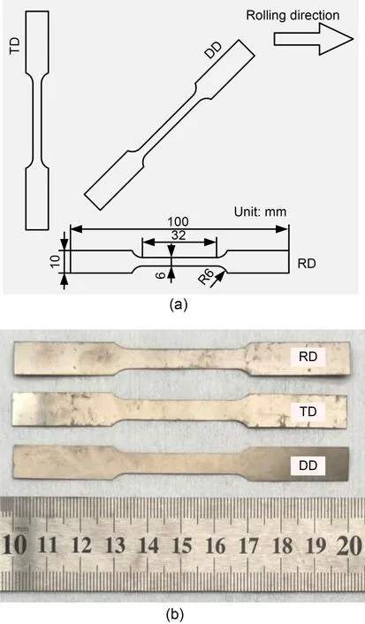
Fig.1 Tensile testing specimens: (a) orientations and dimensions of the tensile specimens;(b) photograph of the prepared specimens
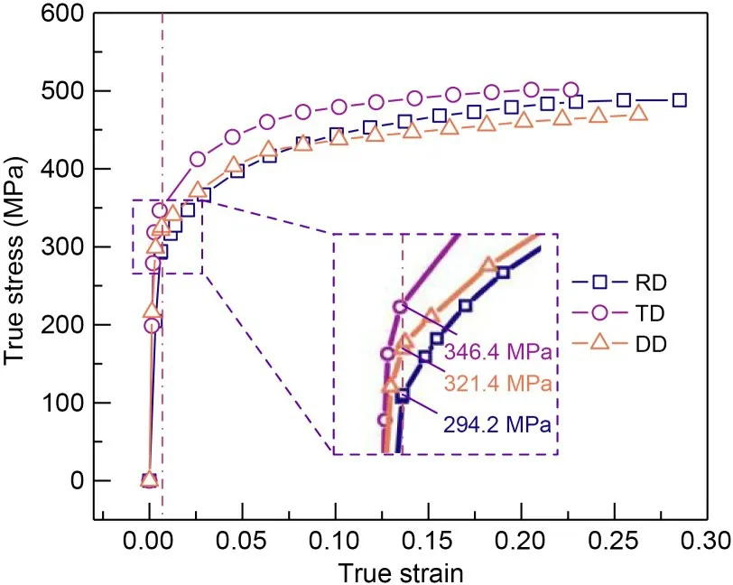
Fig.2 True stress-true strain curves of the CP-Ti specimens
The elastic modulus,yield stress at 0.2% offset,tensile stress,and plastic strain ratio (rvalue) of the CP-Ti sheets were measured in uniaxial tensile tests and the results are shown in Table 1.The plastic strain ratio can be calculated as
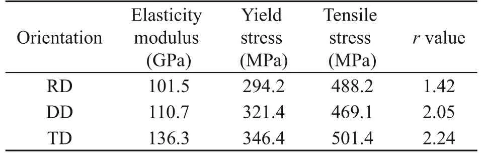
Table 1 Material parameters of CP-Ti obtained from uniaxial tensile tests
whereεwandεtare the principal strains in the width and thickness directions of the specimens,respectively;εlis the strain in the length direction.Due to the small thickness of the specimen,there will be a large error in direct thickness measurement.The volume consistence assumption is considered asεl+εw+εt=0.The plastic strain ratio can be calculated from the strains in the length and width directions measured by the extensometer.
It can be observed from the tests that CP-Ti sheets show great anisotropy in terms of elasticity,yield strength,plastic strain ratio,etc.The RD specimen has the lowest elastic modulus,yield stress,and plastic strain ratio,while the TD specimen has the largest values.These mechanical properties will have great influence on the springback behavior of the thin sheets during microstamping and forming (Jiang et al.,2010).
3 Constitutive modeling and simulation
3.1 Constitutive modeling
To characterize the anisotropic properties of titanium sheets with different orientations accurately,an elastic-plastic constitutive model needs to be developed.The traditional constitutive model generally uses the anisotropic yield and hardening criterion to describe the plastic deformation of the material and ignores the elastic anisotropy effects.This results in significant errors between the predicted and experimental values of the elastic modulus,which will inevitably lead to inaccurate prediction of springback in microstamping.Thus,an orthotropic elasticity criterion needs to be used for the development of a constitutive model for describing the elastic-plastic anisotropy of thin titanium sheets.
As the titanium sheet is ultra-thin,the thickness is much smaller than the length and width,and it can be reduced to the form of planar stress when establishing the constitutive model.In general,the total strain tensor (ε) can be decomposed into two components:elastic strain tensor (εe) and plastic strain tensor (εp).We assumed that the elastic behavior satisfied Hooke’s law and that the relationship between the stress tensor and strain tensor of elastic part can be expressed as
whereσeis the elastic part stress tensor;Cis the modulus tensor.Eq.(2) can be expressed by the engineering elastic constants as
whereσ1,σ2,andτ12are the on-axis stress components;ε1,ε2,andγ12are the on-axis strain components;Sis the compliance tensor,which is the inverse matrix withC;Sijis the compliance component;Eiis the elastic modulus of different orientations;viis Poisson’s ratio of different orientations;G12is the shear modulus.As there is a useful relationship between the engineering elastic constants,obtaining two elastic moduli,Poisson’s ratio,and a shear modulus is sufficient to describe the orthotropic elastic behavior.
Then,an expression for the elastic modulus of the sheet in each orientation is derived.When the compliance tensor direction does not coincide with the material principal direction,it can be referred to as an off-axis compliance tensor.We denoted the off-axis angle on the sheet asθ.The off-axis stress components areσx,σy,andτxy,and the off-axis strain components areεx,εy,andγxy.TheX-axis andY-axis are the off-axis coordinate systems,as shown in Figs.3a-3d.We need to obtain the off-axis compliance tensorfrom the off-axis stress-strain relationship,and the offaxis compliance componentwould be acquired.This would enable us to obtain the expression for the elastic modulus of each orientation.Thus,using the already known on-axis stress-strain relationship,the off-axis stress-strain relationship can be determined by positive stress transformation and negative strain transformation.
Based on Figs.3a and 3b,there is a positive transformation from off-axis stress to on-axis stress,which can be expressed as
whereTσis the stress transformation matrix;mis equal to cosθ;nis equal to sinθ.Eq.(3) can be used to describe the on-axis stress to on-axis strain in Figs.3b and 3c.
In Figs.3c and 3d,we can see that there is a negative transformation from on-axis strain to off-axis strain,thus
Based on the above equations,the relationship between off-axis stress and strain can be obtained,as well as the relationship between off-axis compliance components and on-axis compliance components.By using Eqs.(3) and (5),the expression for the elastic modulus in each orientation of the sheet can be given as
whereEx(θ) is the elastic modulus of a sheet in the main off-axis direction at the off-axis angle ofθ;is one of the compliance components;E1andE2are the elastic moduli in RD and TD specimens,respectively;v1is Poisson’s ratio,which was determined by tensile tests as 0.30.Atθ=45°,Ex(θ) is the elastic modulus in the DD specimen.Substituting the data into Eq.(6),the shear modulus (G12) can be solved and is 40.2 GPa.The relationship between the elastic modulus and the orientation angle of the titanium sheet is shown in Fig.3e.
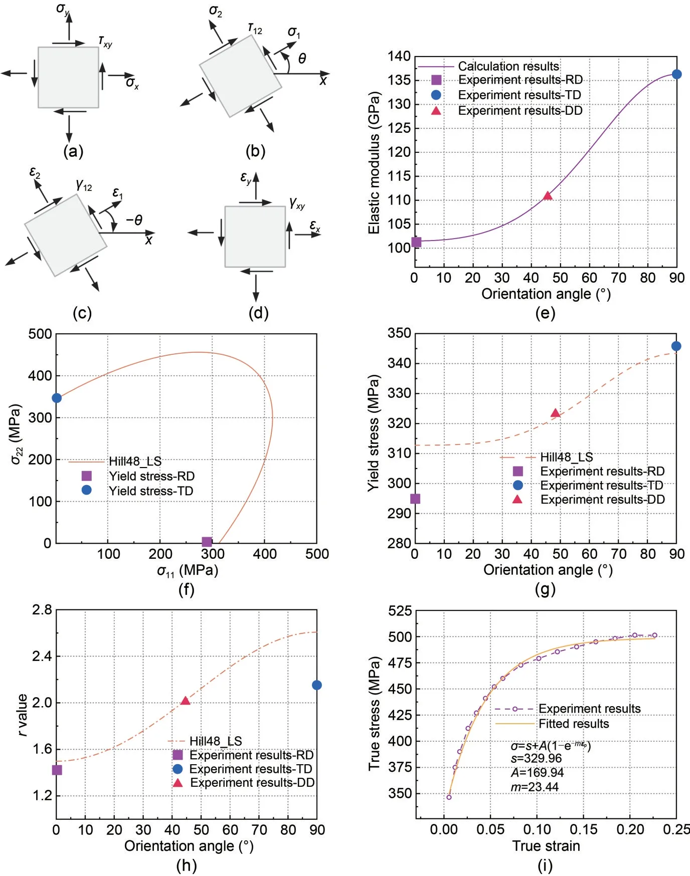
Fig.3 Establishment of constitutive model: (a-d) on-axis and off-axis stress-strain conversion relationships;(e) calculation results of elastic modulus in different directions;(f) yield surface of Hill yield criterion identified by least squares method(Hill48_LS);(g and h) calculation results of yield stress and r value in different directions;(i) fitting curves for the hardening part
Next,because there are significant differences in the plastic behavior obtained for titanium sheets in different orientations,the Hill yield criterion was selected to describe the yielding stress.In the microstamping test of microchannel structures,the specimens were constrained at only two ends and could therefore be considered as in a uniaxial tensile state.Compared with the complex yield criterion,the Hill yield criterion is valid and accurate in predicting the yield stress in the uniaxial tensile state;thervalue prediction matches experimental values closely,although the Hill yield criterion is in error compared to other yielding criteria such as Yld2000-2d in the equi-biaxial stress state (Athale et al.,2018).Kim et al.(2018) measured the yield locus of CP-Ti sheet in states such as uniaxial tensile and plane strain tension,and found that the yield locus was approximated by the Hill anisotropic yield function.
In this study,the Hill yield criterion expression in the planar stress state is
According to the Mohr circle of stress and the plastic flow rule,the equation for the relationship between the yield stress andrvalue and orientation angle can be expressed as
whereσs(θ) andrs(θ) are the yield stress andrvalue of a sheet in the main off-axis direction at an off-axis angle ofθ,respectively.
The traditional identification generally uses thervalue and yield stress identification method.In this study,using the first identification method,thervalues predicted for each orientation are equal to the experimental values.However,the predicted yield stresses for RD,DD,and TD specimens are 294.2,290.1,and 319.3 MPa,respectively,where the yield stress of DD specimen was less than that of RD specimen.It is contrary to the experimental results,and the maximum error is 9.7%.Using the second identification method,the predictedrvalues for RD,DD,TD specimens are 1.85,3.00,and 9.06,respectively,where the predicted value of TD specimen is about four times the experimental value.Therefore,thervalue could not be predicted by this method.The least square (LS)identification method was used to consider the yield stress andrvalue together to minimize the errors.The Hill coefficients were related to thervalue and yield stress in a homogeneous linear equation and solved using the LS identification method,which can be expressed as
wherer0,r45,andr90are thervalues obtained from uniaxial tensile tests along RD,DD,and TD specimens,respectively;σ0,σ45,andσ90are the yield stresses along RD,DD,and TD specimens,respectively.
The results of the parameter solutions for the method are shown in Table 2.The yield surface of the function is plotted by substituting the identified parameters into the corresponding equations.The values of the intersection of the yield surface with theX-axis andY-axis are the yield stresses of the RD and TD specimens,respectively.It is obvious that the yield surfaces have different intersection values with theX-axis andY-axis,indicating that the Hill yield criterion can describe the anisotropy,as shown in Fig.3f.Comparing the experimental values of yield stress for the different orientations with those predicted values,it can be observed that although the criterion using the LS identification method deviated from the experimental values for all three orientations,the errors are small:6.3%,0.44%,and 0.88% for the RD,DD,and TD specimens,respectively,as shown in Fig.3g.Similarly,the experimental results ofrvalue for the different orientations are compared with the predicted values and the small errors between thervalue and the experimental values for this identification method are 5.5%,1.5%,and 16% for the RD,DD,and TD specimens,respectively,as shown in Fig.3h.
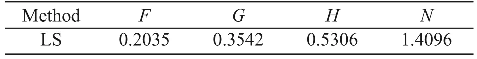
Table 2 Anisotropic parameters of Hill’s 48 for the LS identification method
Through the true stress-strain curve graph in Fig.2,it can be seen that,during the hardening part,the stress of the TD specimen is greater than those of the RD and DD specimens,and the RD and DD curves are close to each other.The curvatures of the three hardening curves are nearly equal.Therefore,we concluded that the difference in the hardening part was mainly caused by the anisotropy of the elastic part and the yield stress.The Voce law was chosen to describe the variation of the flow stress in this study for the hardening curve of the CP-Ti sheet.We fitted the flow stress curve of the TD specimen,as shown in Fig.3i.
Finally,we have developed an orthotropic constitutive model for the thin titanium sheets.Combining Eqs.(6) and (8),the stress-strain relationships for titanium sheets in uniaxial tension can be expressed as
whereσ(θ) is the flow stress with different orientations andεis the flow strain.
Comparing the uniaxial tensile test results with the calculated results by takingθat 0°,45°,and 90°,the constitutive model can describe the elastic-plastic behavior of the material accurately,as shown in Fig.4.All three calculated stress-strain curves can be divided into two parts.The first part is linearly varying and is used to describe the elastic phase of the material.Since the experimental values of the three orientations elastic modulus are used to calibrate the orthotropic elasticity criterion,the slopes of the three calculated stress-strain curves are equal to the experimental results,which accurately describes the elastic anisotropy of the titanium sheet.The second part is the hardening curve starting at the yield stress.The yield stress is calculated for the Hill yield criterion and the largest prediction error occurs in the RD specimen at 6.3%.The curves of the hardening part followed the Voce law,and the stresses of TD specimens were always greater than those of RD and DD specimens.The hardening curves of both RD and DD specimens were close to each other,which was consistent with experimental results.The maximum error in the hardening part appeared in the DD specimen,which was 8.3%.The above results indicated that our developed constitutive model predicts the elastic-plastic behavior of CP-Ti under uniaxial tensile stress state with relatively high accuracy,although the predicted results under complex stress states may not be valid.Also,the model would only be applicable to the study of sheets with thickness much smaller than that of their length and width.
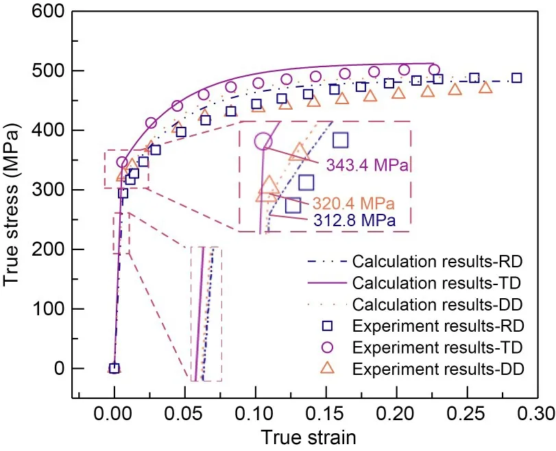
Fig.4 Comparison of experimental and calculated true stress-true strain curves
3.2 Finite element modeling and simulation
To study the CP-Ti sheets in making microchannel structures,finite element modeling and simulations were performed using the Abaqus software (v2020).Here,we focused on the central channel due to its being restrained at both ends by adjacent channels.Both sides of the specimen were free to move and the end of edge channels was unconstrained or less constrained,which resulted in their poor channel shape and inaccurate measurement results.Based on the geometry parameters of the specimen and the tools used,a 3D model of the microstamping process to fabricate the central channel was established,the top was the punch and bottom part was the die.The specimen was 2.0 mm in length,1.0 mm in width,and 0.13 mm in thickness.The symmetry constraints at both ends were set to simulate the loading state of the central channel during microstamping.The punch width (W) and tool clearance (C) were set as 0.70 and 0.30 mm,respectively,while the die width (Wd) was 1.3 mm determined by both.The tool fillet radius (R) and tool depth were 0.10 and 0.60 mm,respectively.The punch speed (v) was set as 0.50 mm/min,as shown in Fig.5a.We can set the above parameters to different values to further investigate the effects of process parameters and tool dimension parameters on the springback of the channel after microstamping.
For FEM,the element meshing and definition of material properties are shown in Fig.5b.Both the punch and die were set as discrete rigid and R3D4 elements and five integration points in their fillet parts were used to increase the mesh density.The meshing of titanium sheet used C3D8R elements with five integration points in the thickness direction.The material properties of titanium sheets were set according to the developed anisotropic constitutive model.In the initial stage,both the top and bottom of the titanium sheet was set in contact with the punch and die,respectively.During the simulation,the coefficient of friction was set as 0.10,which was consistent with the work of Hama et al.(2022),and the die was fixed.When the punch reached a forming depth of 0.40 mm,it returned at the same speed while the titanium sheet was rebounding.The longitudinal and the transverse directions of the material coincided with theX-axis andY-axis,respectively,the material orientation was RD while the opposite was TD.When the two directions were at 45° to theX-axis,the material orientation was DD,as shown in Fig.5b.
4 Experimental setup and procedure
The microstamping experiments were carried out on an INSTRON 5966 material testing machine.The rectangular-shaped specimens with dimensions of 25 mm×10 mm were prepared,and were sampled in three different orientations as for the tensile specimens,as shown in Fig.6a.The same annealing conditions as for the tensile specimens were used to treat the microstamping specimens.After annealing treatment,the specimens can avoid early fracture and reach a greater forming depth due to the elimination of internal stress.This can also shape the specimens in asreceived state to improve the dimensional accuracy after forming.The punch and die were positioned on the corresponding tool bases with locating pins and bolted.The limit cylinders were aligned during installation to ensure that the punch and die could be fully closed during the experiment.The springs were fitted to each of four guide posts.Then the punch base was combined with the die base to complete the assembly on the material testing machine,as shown in Fig.6b.
To validate the FEM and test the formability of CP-Ti specimens in different orientations,a series of tools with different fillet radii were designed and manufactured.The dimensions of punch and die included tool depth (Hx),tool fillet radius (Rx),tool clearance(Cx),and punch width (Wx).Three tools are shown in Fig.7,where tool A,tool B,and tool C have fillet radii of 0.10,0.15,and 0.20 mm,respectively.They were all equal in dimensional parameters except for the tool fillet radius (Hx=0.60,Cx=0.30,andWx=0.70 mm).
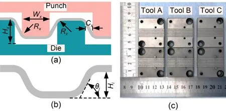
Fig.7 Schematic diagram of process parameters and tool dimensions: (a) definitions of the parameters;(b) measurement of the channel indicators;(c) three sets of tools
We verified the FEM by testing results from the microstamping experiment with tool A.Tool A was first assembled on the tool base in the above-mentioned manner.Next,the symmetry of the gaps between the tools was checked using a high-resolution industrial camera (Lumenera INFINITY-3) with five megapixels.A pre-stamping test was then carried out to determine the punch origin,the specimen was placed on the die,and the punch was moved down.The position was recorded when the value of the force sensor rose rapidly and the pre-stamping test was repeated three times.Finally,the microstamping experiments began.The forming depth of the microchannel was set at 0.40 mm.The specimen was placed on the die and the punch was moved down at 0.50 mm/min until the established forming depth was reached;it was then returned at the same speed.Three separate experiments were carried out for each direction of specimen to ensure accuracy and repeatability.To investigate the formability of titanium sheets in microstamping tests,the above experiment procedure was repeated using tool B and tool C.
The springback of channels occurs mainly in the fillet area and sidewall area.The fillet area is subjected to bending stress and tensile stress while the sidewall area is subjected to tensile stress during the microstamping process.After unloading,the fillet area spreads out causing the changes in draft angle.The sidewall area shrinks along the tensile direction leading to a reduction in channel depth.Therefore,the channel depth (Hi) and draft angle (θj) are selected to evaluate the springback behavior of the specimen,as shown in Fig.7.In addition,the forming load for each group of microstamping experiments was recorded and normalized.Therefore,the influence of the CP-Ti sheet’s anisotropy on the formed channels can be analyzed.
5 Results and discussion
5.1 Simulation results of microstructures stamping
By using the developed constitutive model and the FEM,the microchannels’ stamping process can be simulated;the results are shown in Fig.8.We can see that when the punch moves down to the given depth,three orientation microchannels all produce stress concentrations at the channel’s rounded corners.Due to the differences in the yield stress andrvalue of the three orientation titanium sheets,the maximum stresses of each orientation channel at the corners are not equal,with 578 MPa for RD channel,647 MPa for TD channel,and 604 MPa for DD channel,as shown in Fig.8a.Combined with the predicted results of the Hill yield criterion,we can see that when forming channels to the same depth,a greater forming load is required to cause the TD channel to yield.Therefore,it results in a greater stress concentration and the maximum stress value.
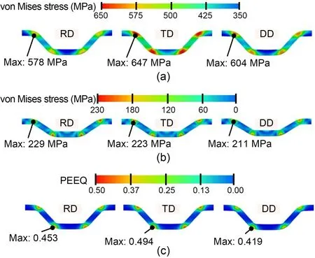
Fig.8 Distribution of stress and plastic strain of thin titanium sheets with different orientations under different microstamping stages: (a) stress distribution when the punch reaches the given depth;(b) stress distribution after the punch unloads;(c) plastic strain (PEEQ) distribution when the punch reaches the given depth
When the punch unloads and returns at the same speed,the three orientation channels exhibit varying degrees of springback.It can be observed that the forming depths of the microchannel are about 279.4 µm for RD channel,276.9 µm for TD channel,and 257.3 µm for DD channel,respectively.Previously,the developed constitutive model made accurate predictions for elastic modulus,yield stress,andrvalue.Where elastic modulus andrvalue are negatively correlated with rebound and yield stress is positively correlated with rebound (Jiang et al.,2010),there is also a strong coupling effect between them.The coupling effect of these parameters on springback is mainly reflected in the stress and equivalent plastic strain.After the punch returns,there are still residual stress concentrations at the round corners of the microchannel,but the residual stress is much lower than the value of maximum stress.The maximum residual stresses are about 229 MPa for RD channel,223 MPa for TD channel,and 211 MPa for DD channel,as in Fig.8b.Comparing before and after punch unloading,the RD microchannel released the smallest stress of 349 MPa during the springback process and the stresses released in the TD and DD channel are 424 and 393 MPa,respectively.This indicates that the RD channel has the best shape retention and has the largest forming depth.The equivalent plastic strain (as PEEQ in Abaqus) shows that the TD channel generates the most plastic strain (about 0.494)during the microstamping process,while the DD channel produces the least value of 0.419,as shown in Fig.8c.This suggests that the TD channel would have more plastic deformation and less elastic recovery when springback occurred.Thus,the TD channel depth is greater than that of DD channel.
5.1.1 Effects of tool fillet radius
In microstamping,the tool fillet radius has a significant influence on the formability of thin titanium sheets.Here,the tool clearance,punch width and press speed remain the same as in Section 3.2.Three tool fillet radii were set as 0.10,0.15,and 0.20 mm,respectively.The simulation results for three evaluation indicators are shown in Fig.9a.We can see that when the tool radius is 0.10 mm,the normalized forming load is maximized.The springback is minimized and the channel depth and draft angle are 276.9 µm and 33.36°,respectively.The difference in the channels at the different orientations is as previously described.The distribution of stress and plastic strain are shown in Fig.9b.As the radius increases to 0.20 mm,the stress concentration and maximum stress value decrease from 647 to 623 MPa,and the plastic strain drops from 0.494 to 0.208.The channel shape also changes from trapezoidal to curved.Due to to the increase in the tool radius,the channel curvature at the corner increases when the sheet is deformed,which helps to reduce the stress concentration.The proportion of material flowing freely increases,giving the channel a curved shape.
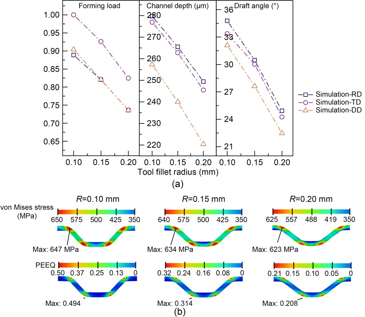
Fig.9 Effects of tool fillet radius: (a) indicators in titanium sheets with different orientations;(b) distributions of stress and plastic strain
5.1.2 Effects of tool clearance
To investigate the effects of tool clearance,tool clearance values were set as 0.20,0.30,and 0.40 mm.Other tool dimensions remained as default.Simulation results of microstamping evaluation indicators versus tool clearances are shown in Fig.10a.It is obvious that the values of all three indicators decrease as the tool clearance increases.In the case of TD specimen,the normalized forming load drops to 0.685 and the depth reduces from 291.2 to 231.1 µm;the draft angle falls from 41.7° to 22.05°.The distribution of stress and plastic strain in the TD sheet after the punch reaches the given depth is shown in Fig.10b.The maximum stresses at the rounded corners of the channels are 635,634,and 625 MPa for three tool clearances,and the differences in the values are not very large,while the stress concentration in 0.20-mm clearance is more obvious and the plastic strain decreases from 0.487 to 0.207 as the clearance increases.During microstamping,the smaller clearance makes the channel deformation more intense and the total amount of material involved in the deformation is less,which also makes the deformation concentrated in the sidewall and fillet areas of the channel,so the channel has more stress concentration,which spreads from the corner to the sidewall and results in greater plastic strain.
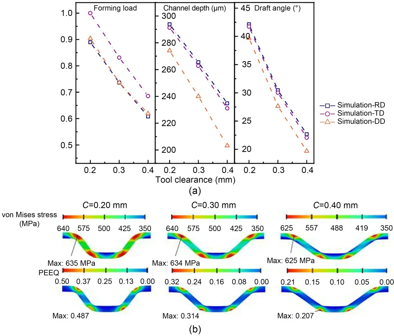
Fig.10 Effects of tool clearance: (a) indicators in titanium sheets with different orientations;(b) distributions of the simulated stress and plastic strain
5.1.3 Effects of punch width
The effects of punch width on microstamping are further investigated;the punch widths were set as 0.60,0.70,and 0.80 mm.The normalized forming load,channel depth and draft angle for the three orientation sheets are shown in Fig.11a,and we can see that the forming loads of the three orientation sheets do not change much with the variation in punch width,while the channel depth and draft angle decrease with increasing punch width.For the TD channel,when the punch width increased,the normalized forming load falls from 1.000 to 0.984,the channel depth decreases from 273.4 to 252.5 µm and draft angle reduces from 31.53° to 29.30°.The distributions of stress and plastic strain are shown in Fig.11b.The degree of stress concentration and stress values at the channel’s rounded corner do not differ significantly.In contrast,the equivalent plastic strain drops from 0.332 to 0.298 with the increasing of punch width,resulting in a decrease in channel depth and draft angle.This illustrates that punch width,unlike tool fillet and clearance,does not affect the intensity of deformation,while the reduction in punch width results in less total material being involved in deformation and an increase in the plastic strain produced for the same deformation.
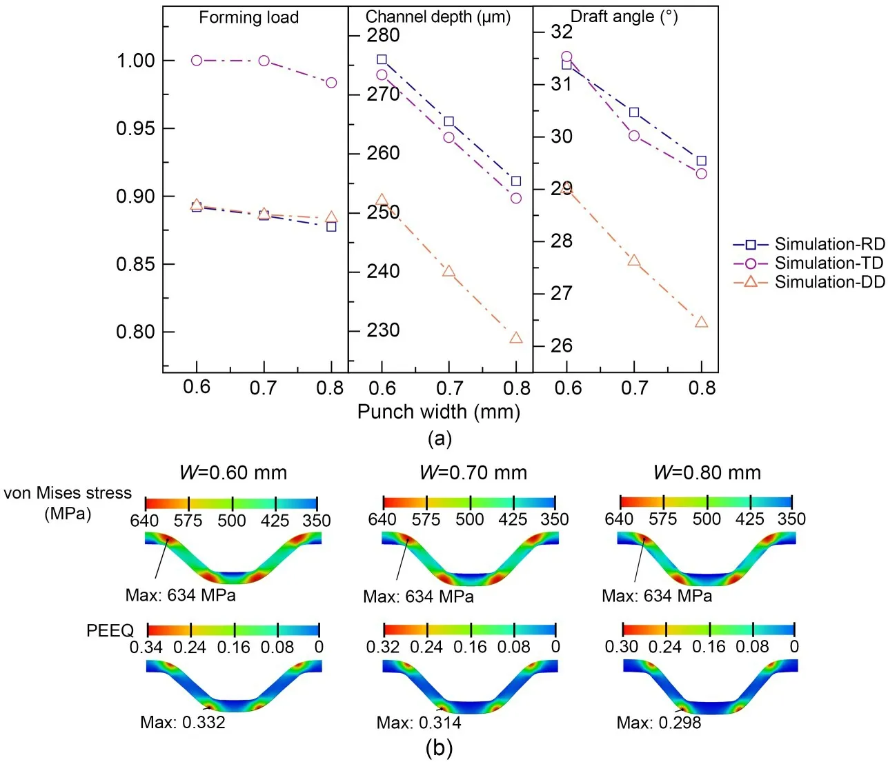
Fig.11 Effects of punch width: (a) indicators in titanium sheets with different orientations;(b) distributions of stress and plastic strain in TD sheets
To conclude,the reductions in tool fillet,clearance,and punch width all increase the forming depth,but also increase the degree of stress concentration,making the channel more susceptible to fracture.We find that compared to the clearance and punch width,the reduction in tool fillet results in a larger depth gain and a more moderate stress concentration.
5.2 Verification of model and experiment results
To verify the accuracy of the developed constitutive model for the microstamping process,a comparison of microstamping experiments using tool A with simulation results was carried out,as shown in Fig.12.The central microchannel was chosen for comparison with the simulation results.Fig.12a shows the channel shape in the experiment and simulation,and it is obvious that the channel shape is trapezoidal at three orientations due to the tool clearance and springback.The depth and draft angle were measured using an Olympus confocal laser scanning microscope (OLS-4100) and the shape of the central channel of the TD specimen was compared as shown in Fig.12a.It can be seen that the simulated channel depth and draft angle results of 276.9 µm and 33.36° have small errors with the experiment results of 0.7% and 0.8%,respectively.
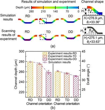
Fig.12 Simulation and experiment results of microstamping:(a) comparison of the channel shape;(b) comparison of channel depth and draft angle
The experimental and simulation results for the three direction channels are shown in Fig.12b.We can see that,due to the anisotropic properties of the material’s mechanical properties,the three directions of the channel exhibit different degrees of springback,with the greatest in DD and the least in RD.The simulation predicts this trend of variation.In the experimental results,the channel depth and draft angle of RD specimen are 279.3 µm and 34.34°,respectively;the channel depth and draft angle of TD specimen are slightly smaller than those of RD specimen at 275.1 µm and 33.63°,respectively;those of DD specimen are 258.9 µm and 32.09°,respectively.The maximum error between the simulation and the experiment results in terms of channel depth occurs in the TD specimen at 0.7% and in the RD specimen at 1.2% for the draft angle.The results show that as the developed constitutive model considers the anisotropy of the elastic modulus based on the conventional plastic anisotropy,the simulation is very accurate in predicting the amount of sheet springback in different directions.The model studied gives exact descriptions of the anisotropy of parameters including elastic modulus,yield stress,andrvalues in thin titanium sheets,and the coupling effect of all these parameters has a significant effect on the springback.It should be noted that when the model is applied by other research groups to study the forming pattern of the sheets in microstamping,on the one hand it has to be ensured that the material used exhibits orthotropic anisotropy and can be approximated as being subjected to uniaxial tensile stress and on the other hand,the thickness of the sheet has to be much less than its length and width,otherwise the stress state of the sheet cannot be considered as a plane stress state.In addition,the stamping speed should be set to the same value as for the uniaxial tensile test to ensure that the identified Hill parameters do not change.
To investigate the forming performances of multichannels from titanium sheets,several sets of tools were designed and manufactured to carry out microstamping experiments.We aim to create channels with little springback before they break.According to the above-mentioned simulation results for the tool dimension parameters,we can see that reducing the tool clearance will significantly decrease the springback,but will result in a greater stress concentration,increasing the risk of a channel’s fracture.In contrast,the changes in punch width,although not sensitive to the stress concentration,produce less plastic deformation during loading and will not be conducive to increasing the channel depth.Therefore,we decided to use tools with altered fillet radius to investigate formability.The results of the fabrication of a microstamping specimen with six channels are shown in Fig.13.
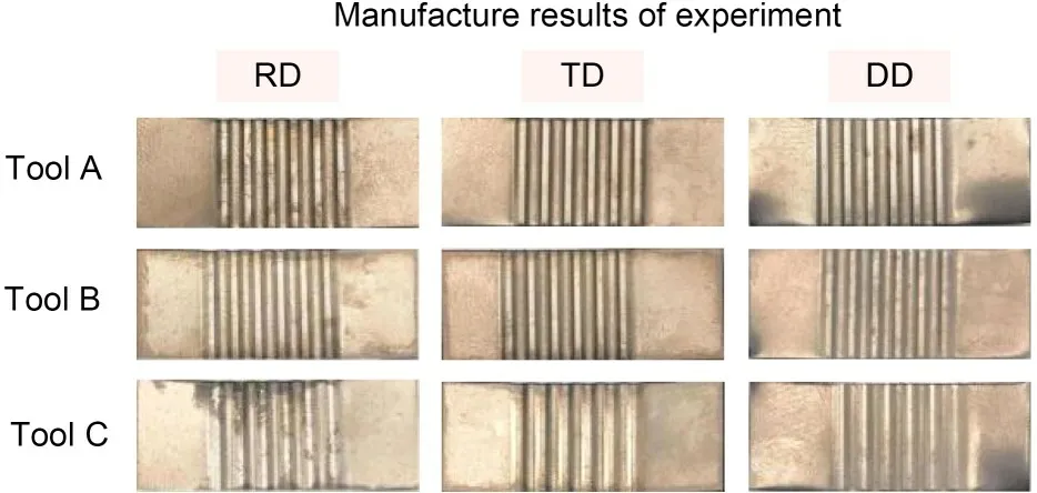
Fig.13 Microchannel fabrication results after microstamping
The measurement results of the channels for different orientation specimens are shown in Fig.14.Generally,the central channel has the lowest channel depth and draft angle,and the edge channel has the largest values for each set of experiments.In experiments of tool B,for RD specimen,the channel depth changes from 265.4 to 277.9 µm and the draft angle varies from 30.57° to 32.21°.The channel depth and draft angle of TD and DD specimens also increase from the central channel to the edge channel.This is because the springback behavior of the channel is divided into springback in the fillet area and springback in the sidewall area.The central and the edge channel have a similar effect on the springback in the fillet area.For springback in the sidewall area,the central channel is constrained by the edge channel and the effect of the drawbead in the sidewall area is more apparent,being subject to greater tensile stress and severe sidewall rebound after unloading.In contrast,the tensile stress in the sidewall area of the edge channel is small and the sidewall springback behavior is not significant.Thus,the central channel rebounds more severely than the edge channel.However,because the edge channel plays the role of the drawbead in relation to the central channel,the shape of the central channel is more regular.
Titanium sheets are all formed to a depth of less than 300 µm due to their small elastic modulus and severe elastic reversion after microstamping.With the increase of tool fillet radius from 0.10 to 0.20 mm,the depth of the center channel of RD specimen is reduced from 279.3 to 248.4 µm and draft angle reduced from 34.34° to 25.31°.The evaluation indicators also decrease in the other two directions.Due to differences in material parameters,the springback of the specimen after microstamping exhibits anisotropy.The elastic modulus andrvalue are negatively correlated with springback and the yield stress positively.The coupling effect between them results in different degrees of springback in different directions of the sheet and it does not disappear with the changes in tool fillet radius.The intersecting surface of the formed channel was observed in the experiments and it was found that the shape of the channel formed with tool A was trapezoidal,while the shape of the channel formed with tool C was curved,as the draft angle also decreases with the increase of the tool fillet radius.According to the experimental results,we can see that the channel springback in the RD sheet is lower compared to the other directions,and the selection of tools with small corner radius can reduce the springback.
6 Conclusions
In this study,a novel orthotropic elastic-plastic constitutive model considering the off-axis elastic modulus is developed to investigate the anisotropic effects of CP-Ti sheets in microstamping.The proposed constitutive model was constructed based on the orthotropic elasticity criterion and Hill’s 48 yield criterion.It can accurately describe the elastic and yield phases of thin titanium sheets with different orientations in the uniaxial tensile state.Numerical modeling was developed,and it accurately predicted the channel depth and draft angle of central channel after microstamping,with maximum errors of 0.7% and 1.2%,respectively.The channel depth and draft angle are the maximum for RD specimen,and the minimum for DD specimen.The causes of anisotropic springback behavior of CP-Ti sheets were analyzed in terms of stress and equivalent plastic strain for each orientation of the sheets.The effects of tool dimensions (tool fillet radius,tool clearance,and punch width) on the forming load and springback behavior are discussed using FEM simulations.The results show that the channel using a tool with 0.10 mm fillet radius at a punch speed of 0.5mm/min obtains a larger channel depth while showing a mild stress concentration,reducing the risk of fracture.Finally,we have produced RD channels with a central channel depth of 279.3 µm and a draft angle of 34.34°.
Our future work will focus on controlling springback and improving the forming consistency of channels by means of compensation.Microstamping experiments utilizing anisotropic materials for manufacturing complex channels will be guided by the constitutive model described here.
Acknowledgments
This work is supported by the National Key R&D Program of China (No.2019YFC1509503),the National Natural Science Foundation of China (No.U1809220),and the Key Research and Development Program of Zhejiang Province(No.2022C01113),China.
Author contributions
Wenze MAO: methodology,validation,formal analysis,investigation,data curation,and writing-original draft &editing;Yancheng WANG: validation,data curation,formal analysis,investigation,and writing-review &editing.Deqing MEI:conceptualization,methodology,resources,supervision,project administration,and funding acquisition.Lingfeng XUAN:methodology and formal analysis.Caiying ZHOU: conceptualization and methodology.
Conflict of interest
Wenze MAO,Yancheng WANG,Deqing MEI,Lingfeng XUAN,and Caiying ZHOU declare that they have no conflict of interest.
 Journal of Zhejiang University-Science A(Applied Physics & Engineering)2023年12期
- Journal of Zhejiang University-Science A(Applied Physics & Engineering)的其它文章
- Key technologies and development trends of the soft abrasive flow finishing method
- Enhanced mixing efficiency for a novel 3D Tesla micromixer for Newtonian and non-Newtonian fluids
- Solid-liquid flow characteristics and sticking-force analysis of valve-core fitting clearance
- Influence of adjacent shield tunneling construction on existing tunnel settlement: field monitoring and intelligent prediction
- GPU-accelerated vector-form particle-element method for 3D elastoplastic contact of structures
- Dynamics of buoyancy-driven microflow in a narrow annular space