
A novel approach for the optimal arrangement of tube bundles in a 1000-MW condenser
2024-01-11 08:07JinjuGUOTaoyeYINShuaiWANGWeiCHENPeiwangZHUKunLUOYunKUANGJieLIUJunjunHUANGBingHUOHuiWANGChunlinZHANGJianWANG
Jinju GUO ,Taoye YIN ,Shuai WANG ,Wei CHEN ,Peiwang ZHU ,Kun LUO,2✉ ,Yun KUANG,Jie LIU,Junjun HUANG,Bing HUO,Hui WANG,Chunlin ZHANG,Jian WANG
1State Key Laboratory of Clean Energy Utilization,Zhejiang University,Hangzhou 310027,China
2Shanghai Institute for Advanced Study of Zhejiang University,Shanghai 200120,China
3Central Southern China Electric Power Design Institute Co.,Ltd. of China Power Engineering Consulting Group,Wuhan 430071,China
4Huanggang Dabieshan Power Generation Co.,Ltd,Huanggang 438300,China
5China Energy Digital Technology Group Co.,Ltd,Beijing 100022,China
1 Introduction
The condenser plays a vital role in the operation of a thermal power generation unit.Its primary function is to remove the heat from the steam that is exhausted from the steam turbine,thereby condensing the steam into water.Additionally,it establishes and maintains a specific degree of vacuum at the exhaust port of the steam turbine,facilitating efficient operation of the turbine (Keshvarparast et al.,2020).The vacuum degree of the condenser is affected by physical factors such as steam-side resistance and heat-transfer efficiency.Optimization of the tube-bundle arrangement in a condenser can improve heat-transfer efficiency,reduce steam-flow resistance,and increase the actual contact area between the steam and tube bundles.This optimization,in turn,reduces the pressure at the steam-turbine exhaust port and the degree of subcooling of the condensed water.Shell-and-tube condensers have been widely used in various configurations and have complex internal structures with numerous heatexchange tubes (Kasumu et al.,2017;Pereira et al.,2021).During actual operation,non-condensable gases such as air often enter the condenser,creating a multi-phase and multi-component flow field on the shell side.This leads to complex 3D flow that has a significant impact on condensation heat transfer,even for small amounts of air (Ahn et al.,2022;Liao et al.,2023).
Both experimental and numerical methods have been frequently used to study condensers.Specifically,experiments allow researchers to obtain various flow and heat-transfer parameters by installing multiple measurement points inside the actual condenser (Huang et al.,2013;Kasumu et al.,2017).Although this method provides first-hand operation data,it can be expensive;it is also difficult to control operating conditions,and impossible to directly measure flow fields that are instantaneously distributed in the condenser.Numerical simulation provides an alternative for analyzing and studying flow dynamics and condensation characteristics under various operating conditions (Seleznev,2007;Zhang et al.,2008,2012).It can also provide comprehensive data for analysis of the tube structure and offer an optimized design scheme for tube-bundle arrangement.
Based on numerical simulation,several studies have investigated the impact of operating conditions and non-condensable gases on heat-transfer characteristics during steam condensation with various tubebundle configurations.Qin et al.(2023) explored in-tube vapor-condensation heat-transfer characteristics at high pressure and found that higher operating pressures led to reduced wall heat-transfer rates.Liu et al.(2021)examined steam condensation in a vertical tube bundle with non-condensable gases and observed that the distribution of key thermal parameters differed from those in a single tube due to cross effects and mixture effects in the condensation-tube boundary layers.Kumar et al.(2023) conducted a 3D simulation of flow condensation of R-124a inside a horizontal tube with hemispherical structure on the inner surface,and found that the vapor quality and liquid-film thickness inside the structured tube were lower than those observed inside a smooth tube.These studies offer valuable insights into the thermal characteristics of steam condensation inside or outside tubes but are limited to simplified condensers with a restricted number of tubes.
To enhance the functionality of the condenser,a considerable number of tubes,ranging from hundreds to thousands,are integrated within the apparatus.Therefore,an alternative approach is necessary to consider the consequential impact of the vapor effects.Most researchers have employed the porous media model to study shell-and-tube heat exchangers and described the vapor area on the shell side using volume porosity(Park et al.,2020).The porous media model accounts for the effect of the solid structure on fluid flow by representing it as distributed resistance added to the fluid (Steefel and MacQuarrie,1996).This model simplifies the problem greatly and can accurately and efficiently describe the overall heat transfer and pressuredrop changes.However,it has limitations when it comes to capturing the influence of the complexity and heterogeneity of pore structure on the flow field.The main reason is that the source terms added in the basic governing equations rely only on porosity and do not account for the actual flow-field structure.In addition to numerical methods,different arrangements of tube bundles have been proposed since the 1960s (Hosseini et al.,2007;Liu et al.,2020).Scientists have studied the performance of condensers with different tubebundle arrangements.Despite the significant progress in research theory and methods,no conclusion has been reached on the optimal tube-bundle arrangement;this is still urgently needed.
Here,we propose a novel approach to address the shortcomings of the traditional porous media model and optimize the condenser tube-bundle arrangement.In this method,the flow field is divided into two kinds of regions,namely the condensation region and non-condensation region.A relatively fine mesh is used in the condensation region,and a source term is added to the governing equations to describe the steam-condensation process.Compared to the porous media model,this method better reflects the flow-field characteristics with different tube-bundle arrangements,while significantly reducing the computational costs compared to direct modelling.The mathematical model is provided in the electronic supplementary materials(ESM),including model assumptions,governing equations of the fluid phase,phase-change model,and numerical procedure.Upon determining the numerical settings and completing the grid-independence analysis,as provided in the ESM,we generated the results which we present and discuss in this paper.
2 Results and discussion
2.1 Effects of tube-bundle arrangements
2.1.1 Flow dynamics
As shown in Figs.1a and 1c,the pressure at the inlet increases by about 50 Pa due to the blocking of the first few rows of tube bundles.To better discuss the heat transfer of each tube,the tube bundle is divided into 10 zones (Condensation01-Condensation10) from top to bottom,among which Condensation10 is the air-cooling zone.Detailed description can be seen in Section S2 of the ESM.The air-cooling zone is the last section where the water vapor flows out of the tube bundle,and the air extraction port is located in it.Directly upon entering the Condensation01 zone,some of the steam drops in pressure due to condensation.Another part of the steam enters the channels on both sides,and gradually enters the Condensation02-Condensation08 zones obliquely downward to condense;then,the pressure gradually decreases by about 100 Pa.Due to the bottom wall being blocked,the pressure in the lower half of the Condensation09 zone is slightly increased,and this phenomenon is more significant for non-uniform tube-bundle arrangements.In the air-cooling zone (Condensation10),the air and uncondensed steam are drawn out at the outlet by the exhaust fan,and the pressure drop is relatively large(about 200 Pa).Regarding the velocity distribution shown in Figs.1b and 1d,the highest velocity is located at the central channel with different tube-bundle arrangements.Specifically,the highest velocity for the uniform tube-bundle arrangement is about 170 m/s,while it is about 180 m/s for the non-uniform tubebundle arrangement.The velocity in the channels on both sides decreases gradually and decreases further once the steam passes through the microchannel.The velocity decreases again to 40 m/s at the bottom of the condenser (Condensation09),and the velocity between the tubes in Condensation01-Condensation09 zones is about 30 m/s.The velocity at Condensation10 in the air-cooling zone is about 70 m/s.
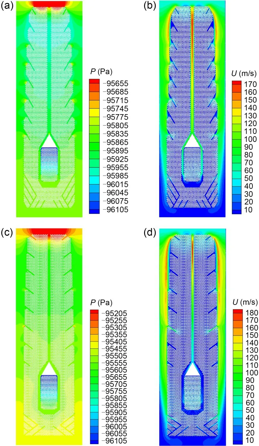
Fig.1 Contour plots of flow dynamics of the condenser with a uniform tube-bundle arrangement (a and b) and a non-uniform tube-bundle arrangement (c and d) (rated air leakage γair=8.0×10⁻⁵ (dimensionless)): (a and c) pressure,P (Pa);(b and d) velocity,U (m/s)
2.1.2 Condensation characteristics
As shown in Figs.2a and 2d,we found that from the periphery to the interior of the tube bundle along with the flow direction of the gas mixture,the water vapor is continuously condensed,resulting in a continuous decrease in the vapor concentration and a gradual increase in the air concentration.The highest mass fraction of air in the condenser with the uniform tube-bundle arrangement is in the Condensation04-Condensation06 zones,with a value of about 0.016,while that with the non-uniform tube-bundle arrangement is in the Condensation02-Condensation06 zones,with a value of about 0.026.In terms of heat-transfer coefficient distribution,the heat-transfer coefficient has a negative correlation with air concentration,as shown in Figs.2b and 2e.In the outer part of the tube bundle,higher water-vapor velocity and lower air concentration result in a higher heat-transfer coefficient.However,in the region near the central channel of the tube bundle,the lower water-vapor velocity and higher air concentration make the heat-transfer coefficient lower.The regions on both sides of the top of the tube bundle appear the highest water-vapor velocity,corresponding to the highest heat-transfer coefficient.In the aircooling zone,the air concentration increases sharply and the heat-transfer coefficient decreases continuously.This is consistent with the flow characteristics and phase-change process of actual condenser operation.As shown in Figs.2c and 2f,the condensation rate has a negative correlation with air concentration and a positive correlation with the heat-transfer coefficient.Compared with the uniformly arranged tube bundle,the non-uniformly arranged tube bundle not only has a lower heat-transfer coefficient near the central channel,but also has three high-air-concentration regions in the outer part of the tube bundle,corresponding to the low heat-transfer coefficient and low condensation rate.
Table 1 demonstrates that under the rated airleakage conditions,the uniform tube-bundle arrangement has a 51.73% lower pressure drop but a 0.96%higher steam-condensation rate than the non-uniform tube-bundle arrangement.In addition,the non-uniform arrangement achieves a higher heat-transfer coefficient of approximately 200 W/(m2·K) higher than that of the uniform tube-bundle arrangement.

Table 1 Condenser performance with different tube-bundle arrangements (γair=8.0×10⁻⁵)
2.1.3 Underlying mechanism
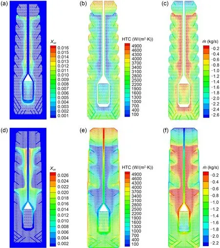
Fig.2 Contour plots of phase changes of the condenser with a uniform tube-bundle arrangement (a-c) and non-uniform tube-bundle arrangement (d-f) (γair=8.0×10⁻⁵): (a and d) mass fraction of air,Xair (dimensionless);(b and e) heat-transfer coefficient,HTC (W/(m2·K));(c and f) condensation rate, (kg/s)
To analyze the influence of local air concentration on the heat-transfer coefficient,we extracted a horizontal line (Fig.3a) from the middle flow field of the condenser with the uniform tube-bundle arrangement.Fig.3b shows the relationship between the air concentration and heat-transfer coefficient on this line.With continuous condensation,the partial pressure of water vapor decreases while the partial pressure of air increases,leading to formation of an air layer.The watervapor/air mixture has to diffuse through the air layer before reaching the surface of the liquid film for condensation so that the flow resistance is increased.In addition,the decrease in the partial pressure of water vapor leads to a decrease in its corresponding saturation temperature,which weakens the condensation process and reduces heat-transfer efficiency.When the diffusion of air molecules leaving the air layer and being carried into it by the main flow reaches a dynamic balance,the air layer is relatively stable.As can be inferred from Fig.3b,the critical value of the air mass fraction is about 0.001.When the air mass fraction increases to 0.001,the air layer is still unstable,with a relatively strong influence.The heat-transfer coefficient decreases from 4250 to 155 W/(m2·K),with a decrease of 96.35%.When the air concentration is greater than 0.001,the air layer stabilizes,with a moderate influence on the heat-transfer process.The area where the air mass fraction is higher than 0.001 is called the airaccumulation area.
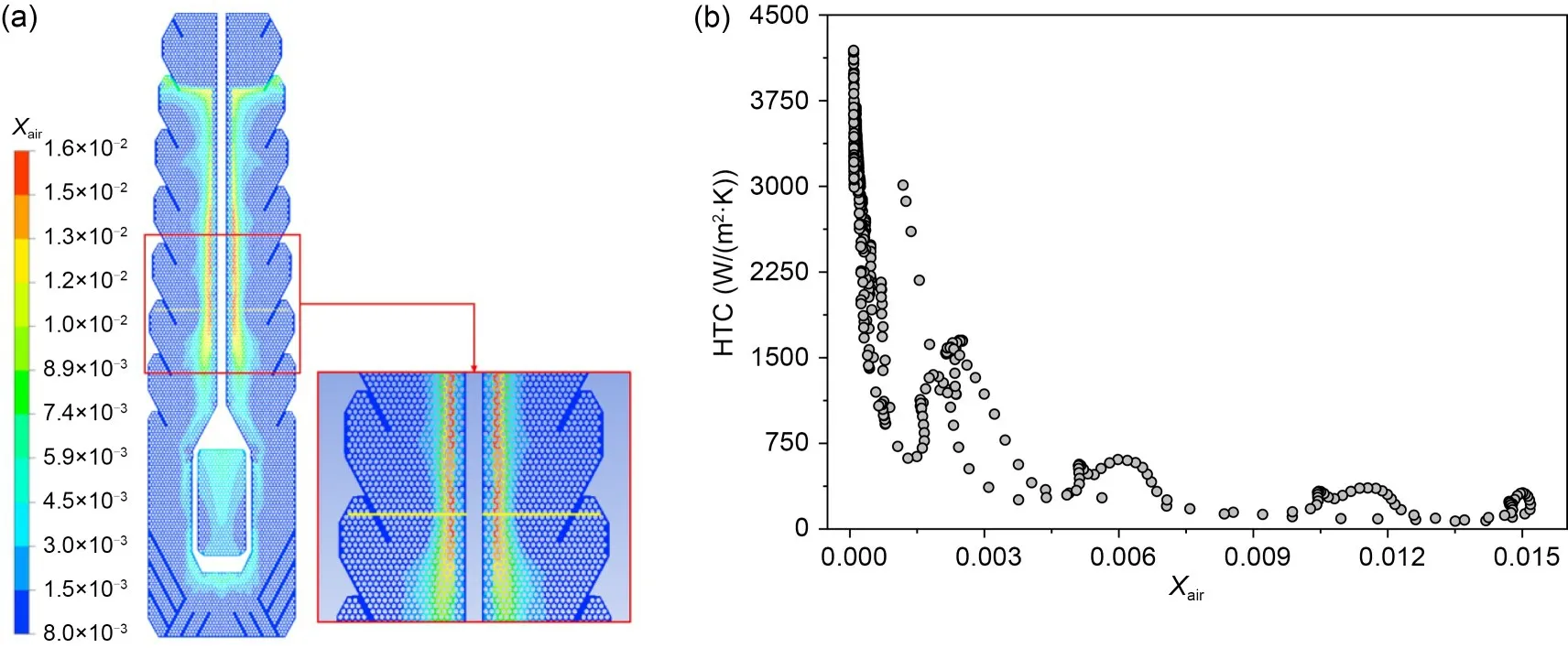
Fig.3 Effect of air concentration on the heat-transfer coefficient with the uniform tube-bundle arrangement: (a) location of the horizontal line;(b) relationship between air mass fraction and heat-transfer coefficient
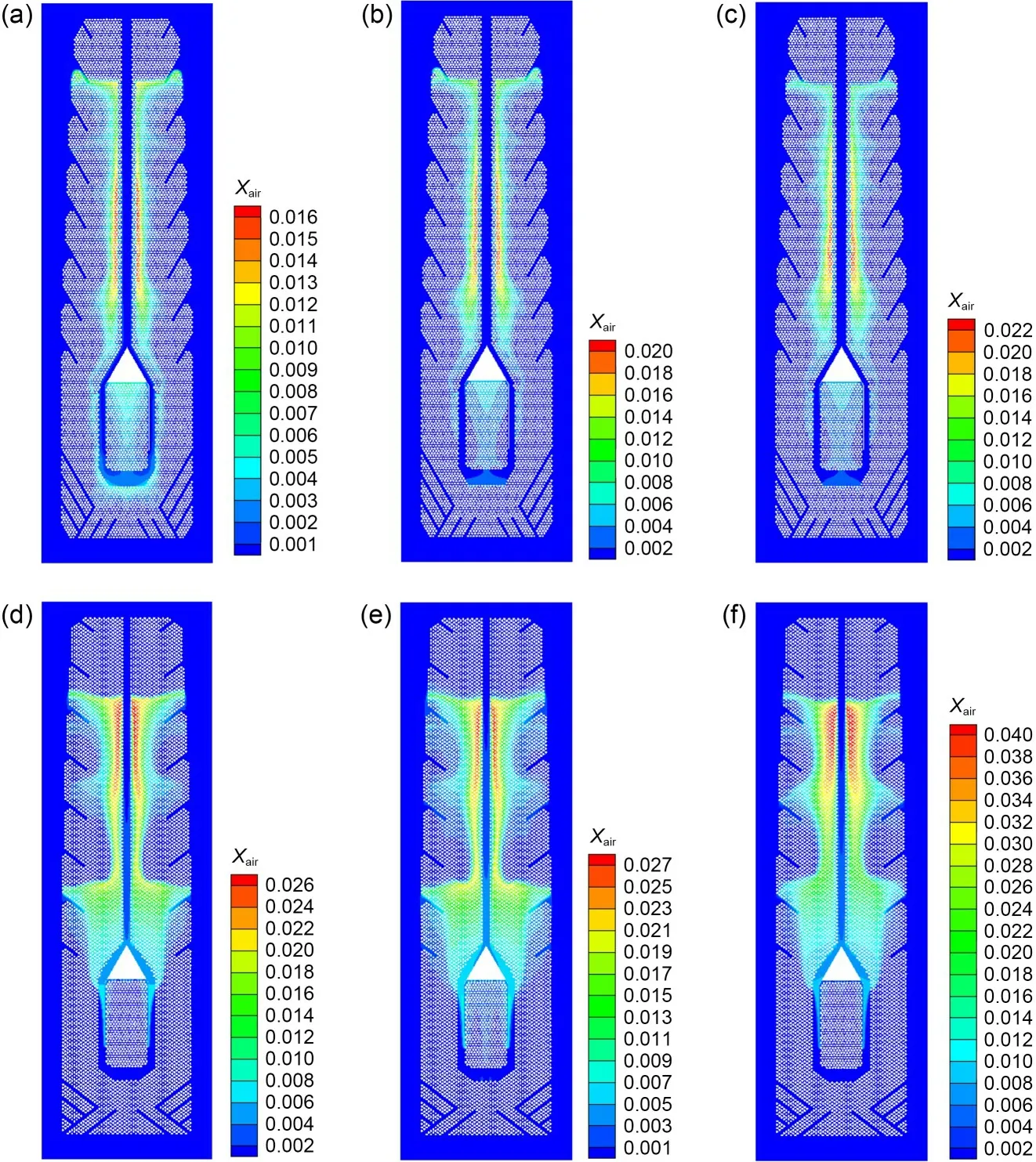
Fig.4 Contour plots of Xair in the condenser with a uniform tube-bundle arrangement (a-c) and a non-uniform tube-bundle arrangement (d-f): (a and d) γair=8.0×10⁻⁵;(b and e) γair=1.0×10⁻⁴;(c and f) γair=1.2×10⁻⁴
2.2 Effect of air leakage
For the uniform arrangement (Figs.4a-4c),as the air leakage increases from 0.00008 to 0.00012,the maximum value of air concentration increases from 0.016 to 0.022;however,the dimension of the air-accumulation area does not increase much.For the non-uniform arrangement (Figs.4d-4f),as the air leakage increases,not only does the maximum value increase from 0.026 to 0.040,but the dimension of the air-accumulation area also increases greatly.This latter phenomenon means that more of tubes cannot transfer heat well.It weakens heat-transfer efficiency and reduces the heat-transfer coefficient.The negative effects on heat-transfer performance in the non-uniform arrangement are more significant than those in the uniform arrangement.
In instances where there is an equal amount of air leakage,the non-uniform tube-bundle arrangement has a higher inlet pressure than the uniform arrangement.The channel between the first rows of tube bundles in the non-uniform arrangement is wider than that in the uniform arrangement,but the gas mixture passing through it impacts the second row of tube bundles directly,causing more significant blockage.Furthermore,the non-uniform arrangement,which has the same number of cooling tubes as the uniform arrangement (but fewer tubes per row and more rows) results in a higher overall pressure drop.This is evident from Fig.5a,where the pressure drop of the non-uniform tube-bundle arrangement is seen to be about 500 Pa more than that of the uniform tube-bundle arrangement.Additionally,as the air-leakage volume increases,the air concentration increases,leading to a lower steam-condensation rate and a higher inlet pressure.The heat-transfer coefficient of the non-uniform tubebundle arrangement is about 200 W/(m2·K) higher than that of the uniform arrangement,as shown in Fig.5b.However,the heat-transfer efficiency decreases as air concentration increases with higher airleakage volume,causing a drop in the heat-transfer coefficient.
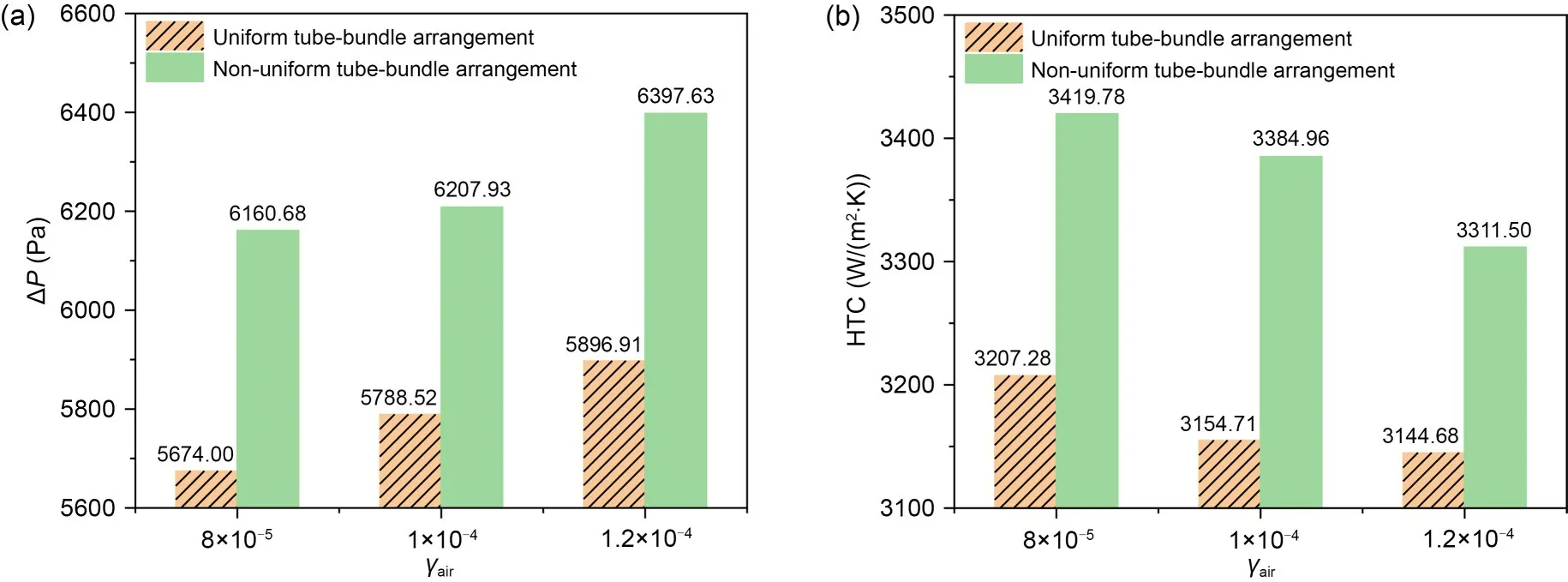
Fig.5 Comparison of performance indicators of the condenser with different tube-bundle arrangements: (a) pressure drop,ΔP;(b) heat-transfer coefficient,HTC
3 Conclusions
1.The dynamic balance of the air layer in the main flow is achieved when the air mass fraction reaches a critical value of approximately 0.001.Below this critical value,the heat-transfer coefficient undergoes a dramatic reduction from 4250 to 155 W/(m2·K),equivalent to a decrease of 96.35%.The region in which the air mass fraction exceeds 0.001 is referred to as the airaccumulation area.
2.The uniform tube-bundle arrangement exhibits a 51.73% lower pressure drop than the non-uniform tube-bundle arrangement under rated air-leakage conditions.However,the non-uniform arrangement achieves a higher heat-transfer coefficient of approximately 200 W/(m2·K) higher than that of the uniform tubebundle arrangement.While increasing the air-leakage volume increases air concentration and inlet pressure,it leads to a drop in steam-condensation rate.Furthermore,heat-transfer efficiency decreases as air concentration increases with higher air-leakage volume,resulting in a decrease in the heat-transfer coefficient.
Acknowledgments
This work is supported by the National Natural Science Foundation of China (No.51806192) and the Fundamental Research Funds for the Central Universities of China (No.2022ZFJH004).
Author contributions
Jinju GUO processed the data curation,helped methodology,and wrote the original draft.Taoye YIN developed the software.Shuai WANG reviewed and edited the final draft.Wei CHEN validated the numerical model.Peiwang ZHU and Junjun HUANG were responsible for visualization.Kun LUO was the project administrator,and was responsible for supervision and reviewing and editing the draft.Yun KUANG and Jie LIU denoted investigation.Bing HUO and Chunlin ZHANG helped methodology.Hui WANG helped supervision.Jian WANG was responsible for conceptualization.
Conflict of interest
Jinju GUO,Taoye YIN,Shuai WANG,Wei CHEN,Peiwang ZHU,Kun LUO,Yun KUANG,Jie LIU,Junjun HUANG,Bing HUO,Hui WANG,Chunlin ZHANG,and Jian WANG declare that they have no conflict of interest.
 Journal of Zhejiang University-Science A(Applied Physics & Engineering)2023年12期
- Journal of Zhejiang University-Science A(Applied Physics & Engineering)的其它文章
- Key technologies and development trends of the soft abrasive flow finishing method
- Enhanced mixing efficiency for a novel 3D Tesla micromixer for Newtonian and non-Newtonian fluids
- Numerical modeling and experimental study of microstamping process for fabricating microchannels using thin sheets of titanium
- Solid-liquid flow characteristics and sticking-force analysis of valve-core fitting clearance
- Influence of adjacent shield tunneling construction on existing tunnel settlement: field monitoring and intelligent prediction
- GPU-accelerated vector-form particle-element method for 3D elastoplastic contact of structures