A Rigorous Analysis of Vehicle-to-Vehicle Range Performance in a Rural Channel Propagation Scenario as a Function of Antenna Type and Location via Simulation and Field Trails
Ran Liu,Daniel N.Aloi
School of Engineering and Computer Science,Oakland University,Rochester Hills,MI-48309,USA
*The corresponding author,email: ranliu@oakland.edu
Abstract: Vehicle-to-Everything (V2X) communications will be an essential part of the technology in future autonomous drive decision systems.A fundamental procedure is to establish a robust communication channel between end-to-end devices.Due to the antenna placed at different positions on vehicles,the existing cellular electro-magnetic (EM) wave propagation modelling does not fit properly for V2X direct communication application.In order to figure out a feasible understanding of this problem,this paper focuses on the propagation channel analysis in a rural Vehicle-to-Vehicle(V2V)scenario for vehicular communication with antenna position experiments at different heights.By adopting the ray-tracing algorithm,a rural scenario simulation model is built up via the use of a commercial-off-the-shelf (COTS) EM modelling software package,that computes the path loss received power and delay spread for a given propagation channel.Next,a real-world vehicle measurement campaign was performed to verify the simulation results.The simulated and measured receiver power was in good agreement with each other,and the results of this study considered two antenna types located at three different relative heights between the two vehicles.This research provides constructive guidance for the V2V antenna characteristics,antenna placement and vehicle communication channel analysis.
Keywords: antenna simulation and measurement;propagation channel modeling;ray-tracing simulation;V2V scenario propagation
I.INTRODUCTION
The communication network has been vastly improved in the past decades.With the advantages of mass data exchange capability and everything online,a fast and reliable long-term evolution (LTE) cellular wireless network has become an essential part of our daily life.The fifth generation (5G) cellular network was conceived to take advantage of massive intelligent multiple-input-multiple-output (MIMO) antenna systems,and mobile edge computing(MEC)technologies are ready in place,the whole network exhibits more robustness and less latency than the LTE network.Cellular vehicle-to-everything(C-V2X)is a novel component of the LTE technology,and the latest new radio V2X(NR-V2X)will play a critical role in the 5G lifetime,especially in the interaction between internet-ofthings (IoT) and the automotive network [1].The basic communication air interface of the system includes cellular communication User-to-UTRAN(Uu)and direct communication PHY sidelink(PC5)mode 4.The Uu interface has been widely applied in vehicle-tonetwork(V2N),vehicle-to-infrastructure(V2I)and its channel characteristics are similar to cellular communication.To support the V2V communication,the PC5’s air interface network needs to achieve improvements in transmitter-receiver scenario changes[2–4].The V2V modeling has been studied over the previous decades[5–10].There are some V2V channel propagation study works on urban/suburban scenario in[11],underground indoor garage with antenna height at 1.7 m in [12].The inter-vehicle communications channel model with antenna was determined in[13–15],while the antenna configuration needs further study.In IEEE 802.11p[16]and 3GPP TR36.885[17]and TR37.885[18],they only considered 1 omnidirectional antenna in the documents.the authors in[19]proposed 4 antenna positions on the roof-top with simulated radiation patterns.And the authors in[20]-with a height of Transmitter (Tx) and Receiver (Rx)antennas relatively close to the ground level-make the V2V channel significantly different from the well studied channels of other technologies such as cellular network,considering the V2V channel information with 4×4 MIMO antenna-array placement on the rooftop but may not be realistic in the real automotive industry products.In most of the previous open reports and specifications [21–24],as in SAE J2945/1 Section 6.4 RF Performance Requirements for the detail specification [25],the antenna should have an omnidirectional radiation pattern on the roof for a singleinput-single-output(SISO)solution.However,due to the vehicle structure and size limitation,this kind of omni-directional antenna is hard to realize in the real world.Some automotive original equipment manufacturers (OEMs) design a sharkfin antenna on the rear area of the vehicle’s roof,which is the peak height of the entire vehicle.It could be a position of the V2V antenna,but in recent years,the panoramic glass roof as a modern trend has led to new car-line design.Since the electrical wall boundary does not exist on the glass material at the front side of the roof,the radiation pattern suffers significant attenuation.One possible solution is to metalize the glass roof,while the high cost of coating materials and additional process work are inevitable.On the technical side,the earlier network access device(NAD)module design has only one transmit path base on 3GPP TS 36 Group release 14 [26].Therefore,the LTE-V2X system can only support one Tx/Rx path.In the novel NAD design,cyclic delay diversity(CDD)is introduced in dual transmit chains following the 3GPP TS 36 Group release 15[27],including two Tx/Rx paths,which could be an ideal NRV2X configuration.The recommendation of these two antennas’position is front-rear directional placement,while most communication scenarios occur in front and rear areas [21] [24] [25] [28],such as forward collision warning,lane change warning,do not pass warning and so on.An alternative antenna position may consider left-right rear mirror placement.In all,the vehicle antenna design and placement require careful consideration of the vehicle structure and styling.
II.RESEARCH METHODOLOGY
The cellular network channel propagation has been heavily studied in the last decades,and the transmission between tower base station and handheld devices can be carried out in both line of sight(LOS)and nonline of sight (NLOS) conditions [29–31].However,the V2V channel propagation needs to be re-analyzed due to the transceiver height change and vehicle’s fast movement.Especially in small-scale fading,it could appear as a rapid fluctuation of the amplitude of a radio signal over a short period of time in travelled distance[29].This research focuses on the impact of the V2V antenna at different heights in the rural communication scenario,which is where the most antenna positions are considered.
· omni-directional antenna as reference at 1.6 m height
· directional antenna at 0.6 m height-bumper level
· directional antenna at 1.0 m height-logo level
· directional antenna at 1.6 m height-roof level
The details for the communication modeling are summarized below:
· two-ray ground reflection pathloss model as reference
· rural-area propagation channel simulation by raytracing
· real-world on-vehicle testing
The next section introduces the characteristic of an automotive low profile directional V2V antenna.After that,the channel characteristics (received power and delay spread) are extracted by the simulation results based on the ray-tracing algorithm.Finally,real world on-vehicle measurements are performed and compared to the theoretical calculation and simulation results.The novelty of this paper is as follows.
(1)A directional antenna is introduced for automotive industry mass production instead of omni-directional prototype sample.
(2) The antenna is tested on full-spherical anechoic chamber with real vehicle placement.
(3)V2V channel characteristics are evaluated through both ray-tracing simulation and real measurement.
(4)The conclusion of this article provided a guideline for the automotive manufacture V2V antenna placement.
III.V2V ANTENNA CHARACTERISTICS
The antenna is the first component on the radio frequency (RF) front-end link,the antenna characteristics are the key parameter in the whole system performance.To meet the automotive industry’s requirements,several aspects of the V2V antenna need to be considered including industrial realization,material cost and ease of installation.Based on SAE J2945/1[25] and SAE J3161/1A [32] requirement,the 3GPP Release 15 [27],the antenna is considered as a dualchannel system.As discussed in the previous section,antenna position should be either the front-rear placement or left-right placement.In typical scenarios[22][25],front-rear communication could cover major usage scenarios.Based on these orientations,the system needs a pair of directional antennas.The antenna includes the following elements: a plastic protective housing,a microstrip feed patch radiator and Fakra®connector.In Figure 1,an on-vehicle antenna is being tested in the SGS®Suzhou MVG SG3000 full-scale anechoic chamber.
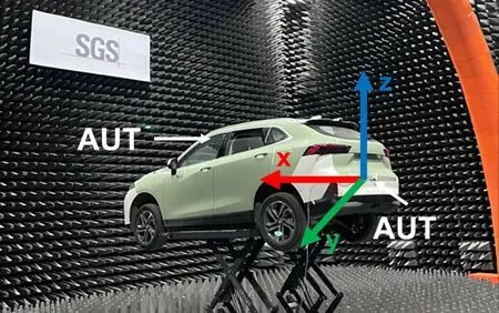
Figure 1. On-vehicle antenna under test (AUT) in an fullscale anechoic chamber with the antenna placement in the front-rear of the vehicle.
As shown in Figure 2,the result of the return loss resonant frequency of the simulated and measured results is well matched in the working frequency Band 47,5855-5925 MHz,and the return loss S-parameter(S11)is below 20 dB.The return loss is required to be lower than 10 dB for industrialization.The production deviation is considered in this antenna’s design and the center frequency could vary in the certain range due to uncertainty of raw materials and assembly consistency.
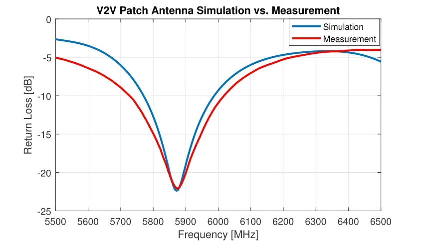
Figure 2. Return loss result (S11) of simulation and real antenna sample result.
According to the testing specification[32],the minimum 70% coverage of the transmit signal strength(TxSS)is 15 dBm,
where,Txpoweris the V2V telematic control unit(TCU) transmission power,Lossrefers to the loss of cable and connector,fHF(h)is antenna placement height factor,and theGainAnt(θ,φ)is free space farfield antenna gain.AssumingTxSS=TxSSmin=15dBm,Txpower=23dBm,the cable and connector loss is 5 dB,the reference antenna height factorfHF(h)=0,whereh=1.5m.
In case of two antenna diversity mentioned in[32],its signal strength is computed as described below in Eq.(4).With CDD technology in 3GPP TS 36 Group release 15[27].The two antennas could work simultaneously.TxSS1andTxSS2are antenna 1 and antenna 2 transmit signal strength respectively,TxSSDiversityis the total diversity transmit signal strength.The system gets diversity gain in the antenna radiation connection area.As followed by this specification,the TxSS is limited by front,rear and side zones.According to Eq.(4),the calculatedGain(θ,φ)min=-3dB,the overall antenna gain requirements in different angle zones are summarized in Table 1.The limits control both the theta angle(θ)and the azimuth angle(φ)with zones.
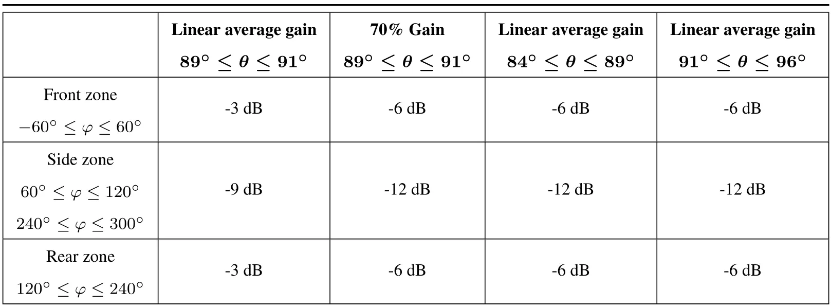
Table 1. Minimum linear average gain(LAG)on free space antenna.
The on-vehicle antenna radiation patterns at three different heights are presented in Figure 3(a)and(b).The far-field radiation gain patterns are measured in a full-scale near-field anechoic chamber of in Figure 1 in thex-zandx-yplane.Due to the surrounding environment of the integrated antenna on the vehicle,such as diffracting and scattering parts of the car body,the antenna radiation patterns exhibit many ripples.As observed from the on-vehicle results,the diversity gain is constant in the front region,with different performance expressed in the rear region,while the front antenna is fixed in the front windshield and rear antennas at three different heights (0.6 m,1.0 m and 1.6 m,respectively).The results conform to limits in Table 1,and the diversity gain results in thex-yplane are provided in Table 2.The region of interest is the rear zone of thex-yplane,with the three different antenna placement heights.The antenna height factor is not observed while the ground reflection is absorbed by radio frequency absorbers on the floor of the anechoic chamber.
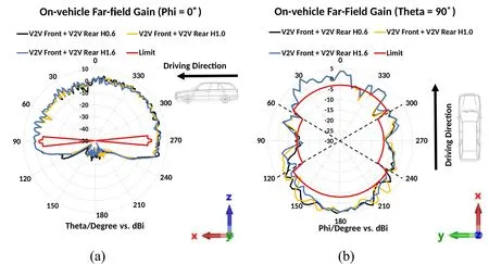
Figure 3. Far-field radiation gain pattern measurement result for vertical linear polarization;(a)on-vehicle radiation gain pattern in x-z plane;(b)on-vehicle radiation gain pattern in x-y plane.
IV.RURAL SCENARIO CHANNEL SIMULATION AND ANALYSIS
A rural road scenario was created using Altair’s WinProp®simulation software shown in Figure 4.It is a commercial-off-the-shelf(COTS)software package for wave propagation study.The simulation algorithm is based on the ray-tracing method.It uses geometry based deterministic models for vehicular channel modeling.Ray-tracing methods could provide accurate channel statistics with actual physical propagation in[33,34].The scenario includes a vehicle body with metal frame and glass windshield,bi-direction boulevards with two car lanes and grass loam on the roadside.The transmit antennas (blue circle: omnidirectional antenna and blue arrow: V2V directional antenna)are placed at front windshield area(at height of 1.5 m),and the patch directional antenna’s radiation pattern is pointed to the forward vehicle direction.The antenna configurations and simulation material properties are illustrated in Table 3 and Table 4.
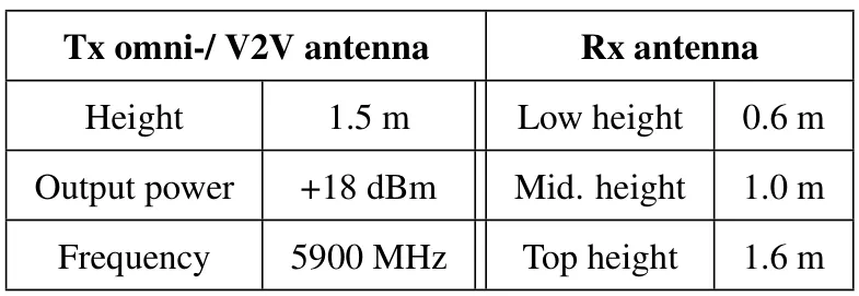
Table 3. Tx-Rx antenna configuration.
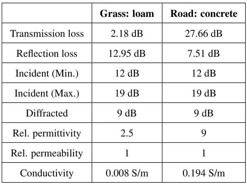
Table 4. Material properties@5900 MHz.
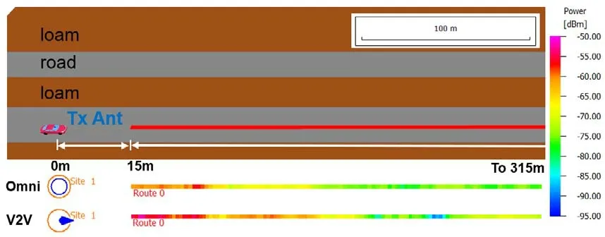
Figure 4. Simulation rural scenario and receive power result over 300 m range.
The reference position of Tx antenna is set as 0 m.The starting point of Rx antenna is set 15 m away from Tx antenna.Rx antenna is followed by the Route 0 with sampling trajectory setting from 15 m to 315 m,and step resolution of 1 m.The received power level in dBm from the colormap on the right side in Figure 4 indicates that the power level of these two kinds of antennas is followed by the Route 0.
Figure 5 depicts the whole scenario prediction area of the received power distribution.Figure 5(a)reveals the omni-directional transmit antenna.At the transmit point,the receiving power distribution is separated widely,which has strong energy to the antenna around the site.Comparing the results with the directional patch antenna in Figure 5(b),the V2V antenna’s measured radiation pattern is pointed to the driving direction as shown by the blue arrow,where most of the power is concentrated toward to the driving direction.Due to high gain directivity of the antenna,the two direction roads and loam could be distinguished by the propagation property of the vertically polarized wave,which however could not be detected by the omnidirectional antenna.
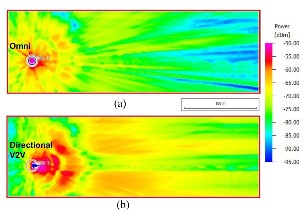
Figure 5. Rural scenario received power of Omnidirectional antenna vs.V2V directional antenna at height 1.6 m;(a)Tx Omni-directional antenna;(b)Tx V2V directional antenna.
Taking the two-ray ground-reflection pathloss model as an example,the distance from the start point to the 1stFresnel zone is called thenear-field region.Accordingly,the distance further away than the 1stFresnel zone is called thefar-field region[35].The 1stFresnel zone distancedfis given by
a=ht+hrandb=ht -hr,htandhrare the height of transmitter and receiver respectively.It can be calculated that theht=1.5 m andhr=1.6 m,the 1stFresnel zone is 182 m.
Figure 6 shows the received power and delay spread vs.distance for the V2V Rx antenna at 1.6 m height.It can be clearly observed the sudden change in the delay spread and fading of the receive power versus distance,where the large-scale fading becomes the dominant part of the wave propagation.The delay spread around 8 ns is after 1stFresnel zone.
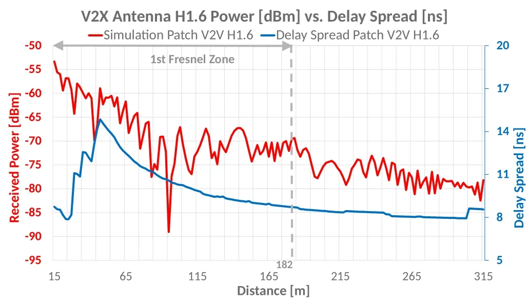
Figure 6. Simulated received power and delay spread versus distance for an antenna height at 1.6 m.
On the near-field region,the power oscillates by the phase construction and deconstruction due to the propagation of rays.The small-scale fading occurs at the time of reflection,diffraction and transmission phenomena existing in ray propagation.Furthermore,a significant change happens in the signal level,which could simultaneously bring an impact on the receiving power sensitivity of wireless communication.The result shows fading around 90-100 m distance,which could be attributed to the problem of signal strength on the wireless communication.A common method toevaluate the multipath propagation is using time dispersion parameter from a power delay profile,such as mean excess delay and RMS delay spread.
The mean excess delay is the first moment of the power delay profile is defined to be[29]
whereakis thekmultipath signal amplitude,τis the excess delay bins,andP(τk)τkdenotes thekreceived power delay profile.
The RMS delay spread is defined as the square root of the second central moment of the power delay profile
where
The coherence bandwidth could be set as correlation function above 0.9[29]
As the Tx-Rx distance enlarges,the delay spread smoothly decreases over the distance.According to Table 5,the calculated 0.9 coherence bandwidth is 2.06 MHz,1.58 MHz and 1.35 MHz with the antenna height at 0.6 m,1.0 m and 1.6 m,respectively and the omni antenna at 1.6 m with 1.65 MHz.The V2V application frequency band is 5900-5910 MHz,and the bandwidth is 10 MHz.The modulation method of V2V transmission is orthogonal frequency division multiplexing (OFDM).There areN=64 subcarriers,and each carrier channel bandwidth is 10 MHz÷64≈0.16 MHz.Due to the benefit of OFDM technology,the coherence bandwidth (the narrowest coherence BW of directional patch antenna at the height of 1.6 m is 1.35 MHz) is much wider than each subcarrier channel bandwidth (0.16 MHz).That is one of advantages of novel code modulation to keep the signal propagation in a state of flat fading rather than frequency selective fading.

Table 5. RMS delay spread with different antenna height configuration.
V.ON-VEHICLE TESTING
Based on the previous section,the simulation provides a method to analyze the V2V antenna performance and channel characteristics.Since the multipath propagation verification needs to be accomplished with realworld vehicle testing,the test setup is performed at an open field rural area in Figure 7.This scenario is a typical rural environment,with the surroundings around the road similar to the simulation environment in the previous section.The trail work is a part of China CV2X Large-scale Pilot Test Activity held in City of Suzhou.
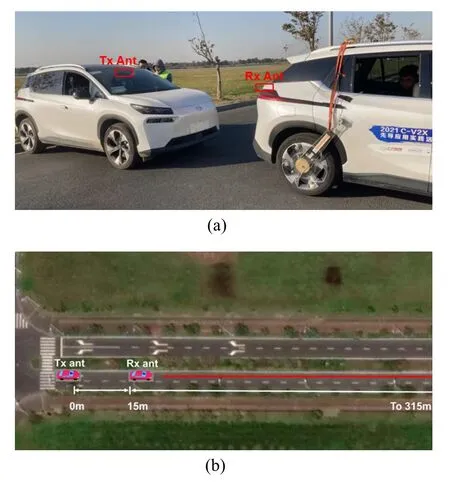
Figure 7. (a) Transmitting antenna (Tx Ant) and Receiving antenna(Rx Ant)setup on the vehicle;(b)A trajectory demonstration of road test on a rural area.
A stationary car is on the left end of the road,with a Tx antenna mounted on the front windshield,as indicated in Figure 7(a).Specific analysis is provided in Section IV.A rover vehicle starts at a reference point with a Rx V2V antenna.The starting distance between Tx antenna and Rx antenna is 15 m,which is the same as the simulation scenario setup.the red line represents the moving trajectory until 315 m away in Figure 7(b).During vehicle testing,the antenna height factor of the Rx antenna is considered as well.The Rx antenna height configurations are placed at 0.6 m,1.0 m and 1.6 m respectively,as shown in Figure 8.
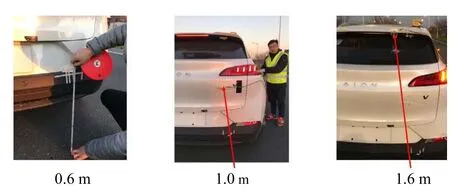
Figure 8. Receiving antenna at three-height placements.
Both the Tx antenna and the Rx antenna share the same configuration as the simulation of Table 3,with the receiving power ranging from-50 dBm to-95 dBm over the 315 m distance.As displayed in Figure 9,when the Tx-Rx distance becomes longer,the received power attenuates as the distance increases.By comparing three antenna heights,it can be found that on the far-field region,the received power of the low antenna (H=0.6 m) is significantly lower than that of the middle-level antenna (H=1.0 m) and the highlevel antenna (H=1.6 m).The results of the calculated average power are given in Table 6.On the far region,the measured average received power is-84.55 dBm,-81.43 dBm and -78.47 dBm for the three antenna heights from low to high respectively.Based on the reference antenna placed at a 1.5 m height,the corresponding antenna factors are-5.92 dB,-2.80 dB and 0.16 dB,respectively.The results are in good agreement with reference SAE J3161/1A [32].This degradation of the low antenna placement height factor could impact the far-field transmitting power and received sensitivity,thereby reducing the communication coverage distance.Thus,the height factor should be considered at the vehicle design stage with the V2V communication link budget calculation in advance.
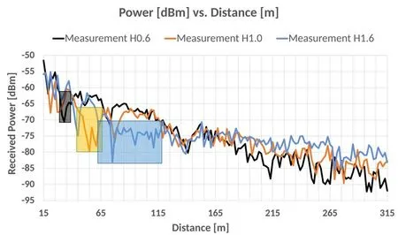
Figure 9. Receiver power vs.distance in three different antenna height configurations.
These results are applicable to the far-field region with proper antenna height calculation.However,the small-scale fading on the near-field region may not be considered,where the signal power experiences a dynamic change over short distance.The higher antenna placement was faced with deeper and longer fades.The fading areas are illuminated in black,orange and blue in Figure 9 for antenna placements of height at 0.6 m,1.0 m and 1.6 m,respectively.Accordingly,the minimum received power is-70.53 dBm,-79.80 dBm and-83.07 dBm respectively in the near-field region.
Figure 10,11 and 12 presents the received power of theoretical two-ray ground-reflection model,rural area simulation and real-world measurement,with Rx antenna heights at 0.6 m,1.0 m and 1.6 m,respectively.As observed from Figure 10,the obtained results agree very well with the received power over the 315 m distance.In the near-field region (15–68 m),it can be found fluctuations in the received signal and small-scale fading in V2V communication system.As the measurement result of the black curve suggests,the fading area is over the distance between 31 to 39m,and the lowest measured power is-70.53 dB,highlighted with the black area.The theoretical calculation and the simulation indicate similar behaviors as well.Meanwhile,the height results of antenna at 1.0 m are depicted in Figure 11,with similar behaviors presented in both near region and the far region.The fading area extends from 41 to 65 m,with a minimum value of-79.80 dBm.As the antenna height moves to 1.6 m,shown in Figure 12,the propagation channel appears more fades in the near region,along with even longer and deeper fading zone.For the distance between 63 to 117 m,the signal lasts over a long distance in a deep fading zone.That presents a big challenge on the communication connection status in such a rapidly fluctuating area.As the received power changes frequently,the signal strength is still in the same level of the far-field region.The communication signal is prone to distortion and interruption due to the weak signal connection.
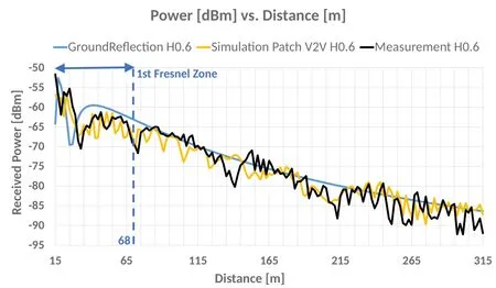
Figure 10. Receiving power of two-ray ground-reflection,rural scenario simulation and real-world measurement with each 1st Fresnel zone,antenna height at 0.6 m.
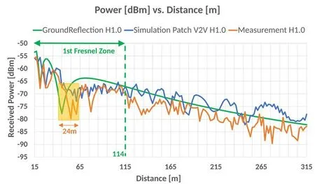
Figure 11. Receiving power of two-ray ground-reflection,rural scenario simulation and real-world measurement with each 1st Fresnel zone,antenna height at 1.0 m.
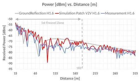
Figure 12. Receiving power of two-ray ground-reflection,rural scenario simulation and real-world measurement with each 1st Fresnel zone,antenna height at 1.6 m.
The ground-reflection model has good prediction ability of large-scale fading,with the path loss suffering continual attenuation in the far-field area.The raytracing simulation of rural scenario is in a good agreement with the real-world measurement at both short and long travel distances.In particular,the simulation result could predict a kind of small-scale fading characterized by rapid fluctuations of the received signal power.The most important fact to consider for the antenna position selection is that the higher antenna placement exhibits better gain benefit in the far-field region while causing more small-scale fading impact on the near-field region.The exact opposite effects could bring for an antenna placed at low height.Therefore,the antenna should be placed at a mid-level height on the vehicle to balance the adverse effects on communication performance of both short and long distance.
The proposed antenna was tested at three possible hidden installation locations.For channel modeling,the IEEE and 3GPP standards [16–18] were modified from cellular network,which requires further improvement for V2V channel analysis.In general,it can be concluded that the proposed research focuses on V2V communication.The antenna should be considered with a directional pattern to cover the main beam area in both the horizontal and vertical planes.For the antenna placement,small scale fading in the near-field region and channel propagation in the far-field region should be taken into account for the antenna height.
VI.CONCLUSION
As V2X technology becomes an essential part of current automotive driving,a stable communication link ensures an end-to-end link.The channel environment and transmission condition have changed under the new frequency band and new application scenarios.
This paper conducted a profound study of V2V direct communication PC5 mode 4 with received power level analysis in a rural channel environment as function of antenna type (Omni-and directional radiation pattern)and heights(0.6 m,1.0 m and 1.6 m)via simulation and field trails.With the latest industry developments considered in the antenna design,it can be concluded the antenna placement is a significant parameter in the whole RF link budget calculation.Based on a rural area scenario,V2V channel characteristics were performed via theoretical analysis,virtual ray-tracing simulation and real world on-vehicle testing with V2V antenna in actual vehicle installations.In this research,channel fading was analyzed in both the small-scale fading transmission in the 1stFresnel zone and large-scale fading transmission in the farfield.Through the closed area channel delay spread and OFDM frame analysis,V2V code modulation system can be explained to overcome frequency selective fading.The combination of mid-level antenna placement and integrated vehicle channel propagation analysis provided a guideline for the V2V antenna design for automotive manufactures.
- China Communications的其它文章
- Secure and Trusted Interoperability Scheme of Heterogeneous Blockchains Platform in IoT Networks
- Intelligent Edge Network Routing Architecture with Blockchain for the IoT
- Privacy-Preserving Deep Learning on Big Data in Cloud
- PowerDetector: Malicious PowerShell Script Family Classification Based on Multi-Modal Semantic Fusion and Deep Learning
- Dynamic Task Offloading for Digital Twin-Empowered Mobile Edge Computing via Deep Reinforcement Learning
- Resource Trading and Miner Competition in Wireless Blockchain Networks with Edge Computing

