UAV-Assisted FSO Communication System with Amplify-and-Forward Protocol under AOA Fluctuations: A Performance Analysis
Maozhe Xu ,Guanjun Xu,2,,,* ,Youran Dong ,Weizhi Wang ,Qinyu Zhang ,Zhaohui Song
1 Shanghai Key Laboratory of Multidimensional Information Processing,East China Normal University,Shanghai 200241,China
2 State Key Laboratory of Integrated Services Networks,Xidian University,Xi’an 710126,China
3 Space Information Research Institute,Hangzhou Dianzi University,Hangzhou,310018,China
4 Peng Cheng Laboratory,Shenzhen 518052,China
5 Communication Engineering Research Center,Harbin Institute of Technology,Shenzhen 518055,China
*The corresponding author,email: gjxu@ee.ecnu.edu.cn
Abstract: Free space optical (FSO) communication has recently aroused great interest in academia due to its unique features,such as large transmission band,high data rates,and strong anti-electromagnetic interference.With the aim of evaluating the performance of an FSO communication system and extending the line-of-sight transmission distance,we propose an unmanned aerial vehicle (UAV)-assisted dual-hop FSO communication system equipped with amplifyand-forward protocol at the relay node.Specifically,we consider impairments of atmospheric absorption,pointing errors,atmospheric turbulence,and link interruptions due to angle-of-arrival fluctuations in the relay system.The Gamma-Gamma and M´alaga distributions are used to model the influence of atmospheric turbulence on the source-to-UAV and UAVto-destination links,respectively.We derive closedform expressions of the probability density function(PDF)and cumulative distribution function(CDF)for the proposed communication system,in terms of the Meijer-G function.Based on the precise PDF and CDF,analytical expressions for the outage probability,average bit error rate,and ergodic capacity are proposed with the aid of the extended generalized bivariate Fox’s H function.Finally,we show that there is a match between the analytical results and numerical results,and we analyze the influence of the system and channel parameters on the performance.
Keywords: amplify-and-forward protocol;angle-ofarrival fluctuations;FSO communication;M´alaga distribution;UAV relay
I.INTRODUCTION
Due to its advantages,such as high transmission rate,low cost of construction,high security,available license-free spectrum,and anti-electromagnetic interference,free space optical (FSO) communication has received a great deal of attention in recent years [1]and has shown promise in terms of solving the “last mile” issue.However,the optical beam is vulnerable to the influence of atmospheric absorption,pointing errors,and atmospheric turbulence,meaning that the performance of the FSO link is significantly degraded and the line of sight (LOS) distance of the FSO link is limited.The emergence of unmanned aerial vehicle (UAV) technology has the advantage of flexible movement,which means that UAV-assisted communication can significantly extend the transmission distance.At the same time,the combination of UAV and mobile edge computing,non-orthogonal multiple access,and reinforcement learning technology can provide wide coverage and secure transmission of RF signals[2,3].The UAV-assisted communication system can be applied to many aspects,such as military reconnaissance,emergency communication,and disaster relief.
Recently,studies of UAV-assisted FSO communication systems have attracted extensive attention.The feasibility of FSO communication between multiple hovering UAVs and detection units was studied in[4,5],and the attenuation effects on the FSO link caused by atmospheric absorption,pointing errors,and atmospheric turbulence were analyzed.Safiet al.focused on ground-to-air FSO communication based on multiple rotors by using a hovering UAV,and the modeling of channel coefficients took atmospheric absorption,pointing errors,and atmospheric turbulence into account [6].Considering the impacts of atmospheric absorption,pointing errors,and atmospheric turbulence on a UAV-based FSO link,Najafiet al.focused on determining the optimized value of the beam width for the minimum outage probability under the constraints of the UAV’s position and orientation [7].In addition to atmospheric absorption,pointing errors,and atmospheric turbulence,angle-ofarrival(AOA)fluctuations resulting from the vibration of a hovering UAV can also lead to performance degradation in a UAV-assisted FSO communication system.Although a physical mechanism for the impact of these AOA fluctuations on FSO communication has been presented,the study of the system performance of UAV-assisted FSO communication systems under AOA fluctuations is still in its infancy.Hence,the investigation of UAV-assisted FSO communication relay systems under the impact of AOA fluctuations has become an important topic.
1.1 Literature Review
As the UAV hovers in the air transmitting optical signals,the vibration of the UAV and wind will cause random deviations in the direction of the beam obtained at the receiver,called AOA fluctuations.When the AOA of the received beam deviates from the detector area,the receiver cannot fully capture the beam leading to the interruption in the FSO communication link and resulting in rapid deterioration of the system communication.In [8],the combined effects of atmospheric absorption,pointing errors,atmospheric turbulence,and AOA fluctuations were considered for an FSO link between two UAVs.The performance of an FSO link between the ground and a high-altitude platform under AOA fluctuations was discussed in[9],and the authors provided an analytical expression that could be used to achieve the optimal system performance.The outage probability of an FSO system under the influence of AOA fluctuations,shot noise,and thermal noise was derived in [10].Subcarrier intensity modulation was used in a UAV-assisted FSO communication system in[11] to suppress the atmospheric turbulence,pointing errors,and AOA fluctuations.Considering the constraints due to atmospheric absorption,pointing errors,atmospheric turbulence,and AOA fluctuations,a channel model of UAV-based FSO communication with nonzero boresight pointing errors was established in[12].The authors of[13]took into account the influence of the UAV position,atmospheric turbulence,and AOA fluctuations on a multi-rotor UAV communication system,and the optimization of different transmittance parameters was discussed.
For the relay node in a UAV-assisted FSO communication system,two well-known relay protocols,known as the amplify-and-forward (AF) and decodeand-forward(DF)protocols,can be used.The AF protocol has a simpler device structure than the DF protocol.A relay node equipped with AF protocol amplifies the received signal and sends it to the destination,which inevitably amplifies the noise.However,a system using the DF protocol yields better performance than one with the AF protocol,since the received signal is decoded before being forwarded to the destination node.Due to the simple derivation of the DF protocol,more research efforts have focused on the AOA fluctuations in UAV-assisted FSO communication systems under the DF protocol.In[14],the performance of a UAV-aided FSO system with the DF protocol was studied,including atmospheric absorption,pointing errors,atmospheric turbulence,and AOA fluctuations,to provide optimal values for the beam width,field-ofview(FOV)angle,and the UAV’s position.Considering the constraints of atmospheric absorption,pointing errors,atmospheric turbulence,and AOA fluctuations,a UAV-assisted dual-hop FSO system with the DF protocol and multiple sources was established in[15].An FSO relay system with the DF protocol was considered under the impact of AOA fluctuations on the FSO link,and the effects of the atmospheric turbulence and the intensity of the pointing errors on the performance of the FSO link were investigated in[16].
To further evaluate the performance of the FSO link,many channel models have been proposed.In[17],atmospheric absorption due to the absorption of molecules and aerosols was investigated for the FSO link.The Beers-Lambert law [18] has been widely used to calculate the signal attenuation due to atmospheric absorption.The authors of[19]proposed a selective relay FSO communication system under atmospheric turbulence with a log-normal distribution,using the DF protocol.The average bit error rate(BER)under different turbulence conditions with Gamma-Gamma and exponentiated Weibull distributions was presented in[20].The log-normal distribution is found to be suitable for weak atmospheric turbulence [21]and the Gamma-Gamma distribution,governed by independent gamma distributions,was used to model the atmospheric turbulence from weak to strong[22].The exponentiated Weibull distribution was adopted for weak-to-strong turbulence in [23].Moreover,numerous fading models for the inevitable pointing errors in the FSO link have been developed.In [24],a fading model for the pointing errors was proposed in which the radial displacement of the beam obeyed a Rayleigh distribution,and the influences of beam width,jitter variance,and detector size were considered.In[25],the authors calculated the outage probability and the average BER of an FSO link under different turbulence conditions with various pointing errors models.
1.2 Motivation
The literature review above shows that the impairments of atmospheric absorption,pointing errors,atmospheric turbulence,and AOA fluctuations in a UAVassisted FSO communication system have been studied in detail.However,there are still many aspects of UAV-assisted FSO communication systems that need to be addressed in terms of AOA fluctuations.
Although many channel models have been proposed to evaluate the impact of atmospheric turbulence on FSO communication,such as the log-normal,Gamma-Gamma,and exponentiated Weibull distributions,the application of the log-normal distribution is bounded by turbulence intensity,and the more widely used Gamma-Gamma and exponentiated Weibull distributions have the drawback of insufficient accuracy under certain turbulence conditions.The M´alaga distribution was proposed as a new model for atmospheric turbulence in[26],and was shown to accurately model various turbulence intensities(from weak to strong).More scattering paths are considered in the M´alaga distribution.The observed field at the receiver of the M´alaga turbulence consists of three items,including the lineof-sight (LOS) component,the scattering term coupled to the LOS,and the energy scattered to the receiver by off-axis eddies.Since the LOS components considered by other distributions are included in the M´alaga distribution,there is a tight relationship between the M´alaga distribution and other distributions.As a multifunctional model,the M´alaga distribution incorporates the log-normal,Gamma-Gamma,Rice-Nakagami distributions,among others,as a special model.Following this,the authors of[27]considered closed-form expressions for the outage probability and average BER of FSO links in the case of M´alaga turbulence under various turbulent conditions.Moreover,the authors of[28]presented closed-form expressions for the outage probability and average BER for an FSO system under atmospheric turbulence with a M´alaga distribution.However,studies of the performance of UAV-assisted dual-hop FSO communication systems in which atmospheric turbulence is modeled with a M´alaga distribution are still in their infancy.
UAV-assisted FSO communication with the DF protocol has been extensively employed due to its high performance.The authors of[29]analyzed the performance of relay-assisted FSO transmission systems under the AF and DF protocols,and their results showed that the system performance is better with the DF protocol than the AF protocol.However,a relay node using the DF protocol needs to be equipped with heavier demodulation equipment,which presents a huge challenge when a UAV with a limited load is used as the relay node.Investigations of UAV-assisted FSO systems with the AF protocol encounter the bottleneck and are limited by the complexity of formula derivation.The authors of[1]deduced closed-form expressions for the outage probability and average BER for a UAV-assisted FSO communication system based on the AF protocol in the form of a complex summation.To obtain a straightforward closed-form expression for a dual-hop FSO communication system with the AF protocol,Zediniet al.used the extended generalized bivariate Fox’s H function(EGBFHF)for formula derivation[30],but ignored the influence of the AOA fluctuations.Therefore,the system performance of the UAV-assisted FSO communication system under AF protocol needs to be further investigated,taking into account the effects of atmospheric absorption,pointing errors,atmospheric turbulence,and AOA fluctuations.Meanwhile,we used the M´alaga distribution suitable for various turbulence intensities.To the best of our knowledge,no study related to this has been conducted.
1.3 Contributions
Motivated by the above analysis,we focus on evaluating the performance of a UAV-assisted dual-hop FSO communication system with the AF protocol in this study,considering the impairments due to atmospheric absorption,pointing errors,atmospheric turbulence,and AOA fluctuations.The atmospheric turbulence in the two hops is modeled using the Gamma-Gamma and M´alaga distributions,respectively.Exact expressions for the outage probability,average BER,and ergodic capacity are derived.
The main contributions of the paper can be summarized as follows:
·A UAV-assisted FSO communication relay system is proposed using the AF protocol.It is assumed that the source-to-UAV link suffers the impairments of atmospheric absorption,pointing errors,atmospheric turbulence,and AOA fluctuations,and the atmospheric turbulence channel of the link between the UAV and the destination node obeys the M´alaga distribution.
·Based on the Meijer-G function,the closed-form expressions of CDF and PDF for the AF protocol system are derived.Analytical expressions of system performance,including outage probability,average bit error rate,and ergodic capacity,are evaluated by using EGBFHF.
·The influence of the main parameters of the system and channel on the system performance is revealed.The results indicate that the existence of a threshold FOV angle and an optimal beam waist can make the system realize the best performance.
1.4 Structure
The rest of the paper is structured as follows.In Section II,we describe the system and channel models of the UAV-assisted FSO communication system.Statistical characteristics of end-to-end system models,including the PDF and CDF,are given in Section III.Closed-form expressions for the outage probability,average BER,and ergodic capacity of the considered system are derived in Section IV.Section V presents the numerical results and detailed analysis.A summary is provided in Section VI.
II.SYSTEM AND CHANNEL MODELS
2.1 System Model
In this work,the UAV-assisted FSO communication relay system shown in Figure 1 is considered with the aim of overcoming the interruption in communication caused by an obstacle between the sourceSand destinationDnodes.A UAV is deployed as the relay nodeRand is equipped with the AF protocol.In the system,two time slots are required to complete the transmission of optical signals.Firstly,a laser diode (LD) in the source node sends an optical signal to the hovering UAV.Next,the AF relaying scheme is applied and the optical signal is assumed to be successfully amplified at the UAV.Finally,a LD in the UAV sends the amplified optical signal to the destination node.We also assume that the three nodes are equipped with only one antenna,and that the UAV hovers at a fixed position around the destination node.The system model proposed in this paper can be widely used in civilian and military applications to provide temporary high transmission rate communications.Typical realistic applications of the proposed system,such as the FSO link between the urban buildings and mountainous areas is disrupted,provide a communication guarantee by this system.More typical practical use cases include agricultural irrigation,emergency communications,disaster relief,and battlefield reconnaissance.
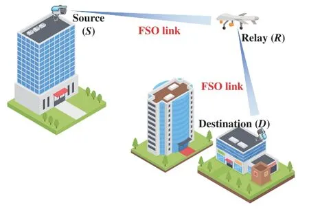
Figure 1. The UAV-assisted dual-hop FSO communication system.
In this system,the signal received by the UAV from the source node can be written as
whereRis the responsivity of the photodetector(PD)in the source and destination nodes,hSRrepresents the channel attenuation coefficient of theS-Rlink,xSRdenotes the optical signal on theS-Rlink transmitted with powerPt,Ptis the average optical power per link,andnSRis the background noise of theS -Rlink,which is assumed to be additive Gaussian white noise(AWGN)with zero mean and varianceσn12,i.e.,nSR~N(0,σn12).Various noises,such as the background noise,shot noise,and thermal noise,will significantly affect the performance of this end-to-end system.Only background noise is considered in this paper to highlight the comprehensive impact of atmospheric absorption,atmospheric turbulence,pointing error,and AOA fluctuations on the system performance.The variance in the background noise is written asσn2=2eBeRPb[9],whereeis the elementary charge,andBeis the signal bandwidth of the PD (in Hz).Pbis the background light power,withPb=NbBoΩFOV Ar,whereNbis the spectrum of radiation about a light wavelengthλ,Bois the bandwidth of the filter at the receiver,ΩFOVis the receiver FOV,andAris receiver lens area(in cm2).ΩFOVcan be written as ΩFOV=2π(1-cos(θFOV)),whereθFOVis the FOV angle.The signal at the destination node is expressed as
whereGis the gain,hRDrepresents the channel attenuation coefficient of theR -Dlink followingnRD~N(0,σn22).
In this work,the intensity modulation/direct detection (IM/DD) technique is employed for signal transmission and receiving.Mathematically,the instantaneous signal-to-noise ratio(SNR)of thei-th FSO link can be written as
wherei=1 and 2 represent theS -RandR-Dlinks,respectively.
2.2 Channel Model
In this study,we consider the atmospheric absorptionhl,the atmospheric turbulencehat,the pointing errorshpe,and the link interruptionhAOAdue to AOA fluctuations.In an optical communication system,the amplitude and phase of the optical signal are distorted due to the absorption and scattering effects of the atmospheric environment on the light.Although the transceiver orientation of each FSO link can be aligned using advanced alignment technology,pointing errors and AOA fluctuations always exist,which result from the vibrations of the receiver.
The atmospheric absorption is normally measured by the Beer-Lambert law[18]as
whereZis the distance of the FSO link,andξis a parameter related to weather visibility and optical wavelength.Values ofξunder different weather visibility conditions at a wavelength of 1550 nm can be found in[31].
Furthermore,atmospheric turbulence causes attenuation of the optical signal during propagation.Atmospheric turbulence refers to the exchange of water,dust,momentum,and heat in the atmosphere,which leads to beam propagation and optical scintillation,thus affecting the performance of an atmospheric optical communication system.Compared with the Gamma-Gamma distribution,the M´alaga distribution yields higher accuracy under conditions of weak to strong turbulence.It can also be transformed into other types of distribution under certain parameter conditions,such as log-normal,Gamma-Gamma,and Rice-Nakagami distributions,although its mathematical expression is more complicated than the Gamma-Gamma distribution.To carry out a comprehensive investigation on the impact of atmospheric turbulence on theS-RandR-Dlinks,we use the Gamma-Gamma and M´alaga distributions,respectively.The PDF forhatusing the M´alaga distribution can be written as
and Λ=.Note that the parameterφdenotes the number of large-scale cells in the scattering process andφis the fading parameter.The combination of these two parameters represents the atmospheric turbulence conditions,where large values of the parameters indicates weak turbulence.ζ=2b(1-ρ) is the average power of the scattering component received by off-axis eddies,where 2bis the average power of the total scatter components,andρis the amount of scattering power coupled to the LOS component.χ=Ω+2bρ+2(2bρΩ)0.5cos(θA-θB)is the average power from the coherent contributions,where Ω is the average power of the LOS component,andθAandθBare the phases of the LOS and the coupled-to-LOS scatter terms,respectively.The values of large-scale and small-scale fluctuation parameters,such asρ,ζ,χ,φandφ,will transform the M´alaga distribution model into different statistical models,which can be found in[26].
The PDF forhatcharacterized by the Gamma-Gamma distribution can be written as[31]
where Γ(·)is the Gamma function andis the Meijer-G function [32].αandβare parameters representing the large-scale and small-scale eddies in the scattering process[22].
In addition to the atmospheric absorption and turbulence,pointing errors also affect the system performance.For a transceiver fixed on a tall building,the reliability of the FSO link is severely limited by pointing errors caused by wind load and the thermal expansion of tall buildings.The pointing errors can be expressed as the deviation between the center of the beam and the center of the aperture of the receiver.The PDF forhpecan be written as[9]
For small values ofθd[9],we use the approximate expression cos(θd)≈1 to facilitate the following derivation.
In addition to the above impacts,the AOA fluctuations also have significant effects on the optical link,and can lead to serious performance degradation or even link interruption.The beam will be completely captured by the PD when the beam is within the receiver’s FOV,and vice versa.To make the analysis tractable,we have[11]
According to [13],θdfollows a Rayleigh distribution as follows:
According to the above analysis,the channel coefficients of thei-th FSO link can be written as
III.STATISTICAL CHARACTERISTICS OF END-TO-END SYSTEMS
3.1 PDF and CDF for the S-R Link
For theS -Rlink,we consider the impairments of atmospheric absorption,pointing errors,atmospheric turbulence,and AOA fluctuations.We assume that the atmospheric turbulent channel condition obeys a Gamma-Gamma distribution.According to (13),we have the optical channel coefficient of theS-Rlinkh1ash1=.For ease of derivation,we definehlap=.Hence,the PDF forhlapcan be written as
where T1=andσr1is the jitter deviation in theS -Rlink.We then haveh1=hlaphAOA,and the PDF forh1can be written as
Substituting (12) and (15) into (16),and using the identityδ(ax)=and[34],we can derive the PDF forh1as
UsingFX(x)=fX(x)dxfor(17),and applying[33],the CDF forh1can be obtained as
From (3),we haveh1=.Hence,by substituting(4)into(18),the CDF forγ1can be obtained as
whereZ1is the distance of theS-Rlink.By differentiatingγ1in(19),and using[33],the PDF forγ1can be obtained as
3.2 PDF and CDF for the R-D Link
For theR-Dlink,the atmospheric absorption,atmospheric turbulence and pointing errors are considered.We assume that the UAV hovers around the destination node.Since there is only a short distance between the UAV and the destination node,we ignore the influence of AOA fluctuations on theR-Dlink.From(13),we haveh2=.The PDF forh2can then be written as
By inserting (4) and (22) into (23),the PDF forγ2can be written as
whereZ2is the length of theR -Dlink.FromFX(x)=∫and[33],the CDF forγ2can be obtained as
3.3 PDF and CDF for the End-to-End Link
In the relay system considered here,we use AF protocol with fixed gain,which is suitable for a UAV with a limited load.The instantaneous SNR between the source and destination can then be written as[35]
whereγ1is the instantaneous SNR of the FSO link between the source and the relay,andγ2is the instantaneous SNR of the FSO link between the relay and destination.Cis a constant which is directly related to the fixed gainGThe CDF for the end-to-end link can then be written as[36]
which can be rewritten as
By converting (28) to a double integral,and interchanging the integrals,we have
By substituting (19),(20),and (25) into (29),and with some algebraic manipulations,we obtain
Then,by using the definition of the EGBFHF [37],we obtain a closed-form expression for the average BER as (32),whereτ5=andτ6=.
IV.END-TO-END PERFORMANCE ANALYSIS
To analyze the performance of the UAV-assisted dualhop FSO communication system,we derive closedform expressions for the outage probability,average BER,and ergodic capacity in this section.
4.1 Outage Probability
The threshold SNRγthis used to ascertain the quality of service.If the instantaneous SNRγis less thanγth,the communication link will be considered as interrupted.The outage probability is formulated asPout(γth)=Pr(γ <γth).Hence,settingγ=γthin(30),the outage probability can be written as(33).
4.2 Average BER
In addition to the outage probability,the average BER is another important indicator characterizing the system performance,and indicates the percentage of error information in the total information during data transmission.The average BER with different modulation schemes can be written as[38]
where the parameterspandqare altered based on the modulation scheme.For instance,when the system uses binary phase shift keying (BPSK),pandqare set to 0.5 and 1,respectively,whereas when the system uses binary frequency shift keying (BFSK),pandqare set to 0.5 and 0.5,respectively.By substituting (A.3) into (34),and then using [32] and (A.2),we obtain (35).
From the definition of the EGBFHF,we can obtain a closed-form expression for the average BER as(36),whereτ7={(3-T1,1),(3-α,1),(3-β,1)}andτ8={(
4.3 Ergodic Capacity
Ergodic capacity refers to the time average of the maximum information rate of a random channel in the fading state,which is suitable for the study of delayinsensitive services.The ergodic capacity of the considered UAV-assisted dual-hop FSO communication system operating under the IM/DD technique can be written as[29]
Substituting(31)into(37),and using[39],[33]and[32],we have(38).
According to the definition of the EGBFHF,the ergodic capacity can be derived in closed form as(39),where
V.SIMULATION ANALYSIS
In this section,we provide numerical results to illustrate the influence of some key parameters on the system performance,and use Monte Carlo(MC)simulation (107random variables) to verify the correctness of the analysis results.Unless otherwise specified,we setρ=0.596,b0=0.1079,Ω=1.3265,C=0.6,ξ=0.2208,L=2,Be=1,R=0.9,Nb=10-3,Bo=10,r2=0.05,andγth=10 dB[9].We assume that the noise power is equal for the two FSO links,and that the parameters of the pointing errors for the two FSO links are same.For the M´alaga distribution,the combinationφ=2.296 andφ=2 is used to represent strong turbulence,φ=4.2 andφ=3 to represent moderate turbulence,andφ=8 andφ=4 to denote weak turbulence.For the Gamma-Gamma distribution,strong,moderate and weak turbulence conditions are characterized by combinations of the fading parametersαandβas (4.2,1.4),(4,1.9),and (11.6,10.1),respectively[40].
Figure 2 demonstrates the outage probability versus average optical power under different AOA fluctuations and relay protocol.The analytical results agree with the numerical results in Figure 2.Compared to the AF protocol,the DF protocol has a lower outage probability in case AOA fluctuations are not considered.For example,whenPt=30 dBm,the black line indicates an outage probability close to 1×10⁻⁷,and the red line has an outage probability of 9×10⁻⁷.In addition,the AOA fluctuations deteriorate the outage probability for AF protocol.For instance,whenPt=30 dBm,the outage probability represented by the blue line is close to 4.1×10⁻⁶,and the black line obtains an outage probability close to 1×10⁻⁷.Therefore,we conclude that AOA fluctuations will degrade the outage probability,and the system performance of the AF protocol is reasonably better than that of the DF protocol.
Figure 3 illustrates the outage probability of the relay system for varying values of the average optical power under the IM/DD technique.The FOV angleθFOVis set to 35,40,45,and 50 mrad,respectively.It is worth noting that the FOV of the receiver is large for high values ofθFOV.The analytical results show good agreement with the simulation results in Figure 3,and we conclude that the outage probability decreases as the FOV angle increases.This phenomenon can be explained by the fact that a larger FOV angle overcomes the AOA fluctuations,which in turn reduces the outage probability.For example,whenPt=40 dBm,the outage probability forθFOV=50 mrad is nearly 3.8×10⁻⁶,compared with values of 3.9×10-5,3.4×10-4,and 2.2×10⁻³forθFOV=45,40,and 35 mrad,respectively.In addition,for smallPt,the end-to-end outage probability decreases with an increase inPtdue to the increase in the instantaneous SNR.However,for large values ofPt,the outage performance approaches the asymptotic bound.For instance,forθFOV=40 mrad,the outage probabilities are 7.5×10⁻⁴and 4.1×10⁻⁴forPtvalues of 10 and 15 dBm,respectively,and the outage probabilities are 3.4×10⁻⁴whenPtis 35 or 40 dBm.
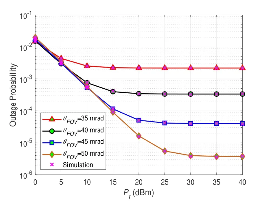
Figure 3. Outage probability versus average optical power of system links for various FOV angles (wz=2 m,σr=0.75 m,σ0=10 mrad).
The impact of the threshold SNR and average optical power on the outage probability of the relay system is illustrated in Figure 4.It can be observed that the analytical results closely match the numerical results.As expected,the relay system has a lower outage probability with increasing values ofPtandθFOV,which is consistent with the phenomenon shown in Figure 3.However,an excessive increase inθFOVwill introduce undesired background noise,and this will slightly increase the outage probability.For example,whenγth=10 dB andPt=30 dBm,the outage probability forθFOV=60 mrad is close to 3.4×10⁻⁷,which can be compared with values of 3.6×10⁻⁷and 4×10⁻⁷forθFOV=65 and 70 mrad,respectively.Moreover,the outage probability increases with an increase in the threshold SNRγth.The above variation can be explained by the fact that a greater proportion of signals lower thanγthmean that the system will be interrupted.For instance,whenθFOV=70 mrad andPt=30 dBm,the outage probability is 4×10⁻⁷atγth=10 dB,which increases as expected to 1.1×10⁻⁶atγth=15 dB.
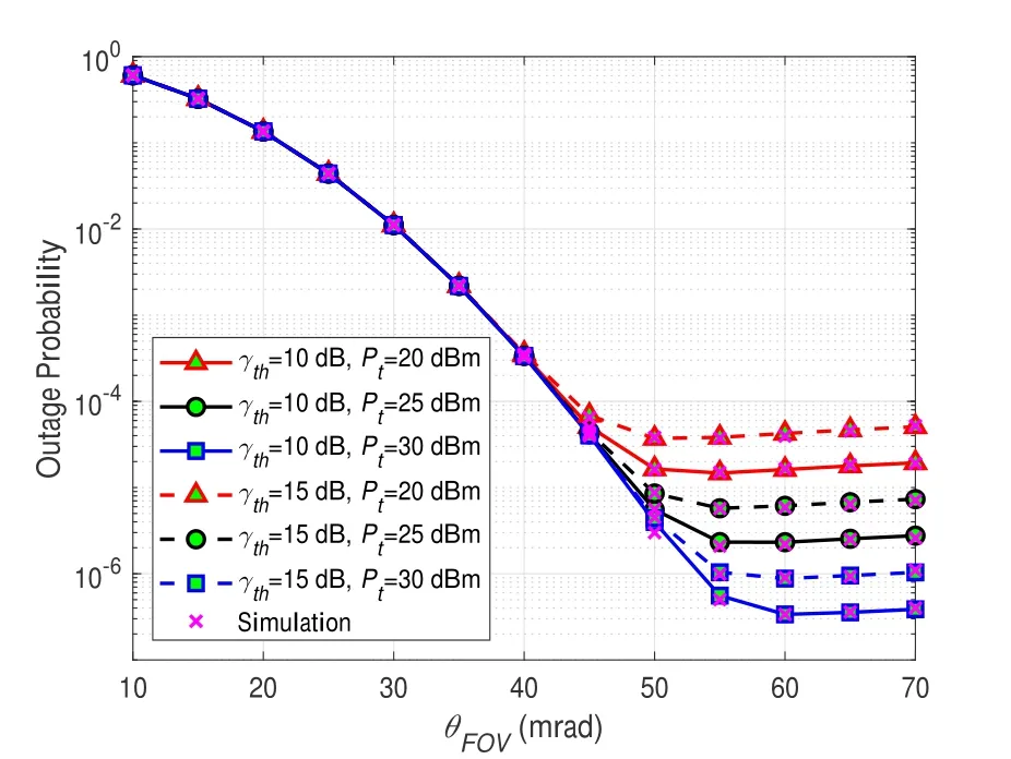
Figure 4. Outage probability versus FOV angle for varying threshold SNRs and average optical power(wz=2 m,σr=0.75 m,σ0=10 mrad).
Figure 5 demonstrates the impact of the average optical power on the outage probability of the relay system for varying jitter deviation,σr=0.75,0.85,and 0.95 m.The analytical results closely match the numerical simulation results.As expected,with an increase in the average optical powerPt,the outage probability first decreases and then approaches the asymptotic bound,as shown in Figure 3.It can be seen from the figure that the outage probability decreases with a decrease in jitter deviation.This phenomenon can be explained as follows: with a reduction inσr,there is a decrease in the mathematical expectation and variance of the random variable representing the deviation distance between the beam center and the lens center,which are expressed asand.Hence,more beams are steadily and accurately received during this period.It should be noted that an increase inPtcan compensate for the impact ofσron the outage probability.For example,to obtain an outage probability of 1×10⁻⁷,the values ofPtare approximately 8.7,12.5,and 17 dBm whenσr=0.75,0.85,and 0.95 m,respectively.
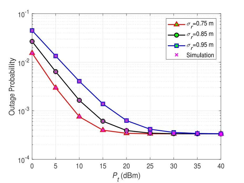
Figure 5. Outage probability versus average optical power for varying jitter deviations(wz=2 m,θF OV=40 mrad,σ0=10 mrad).
Figure 6 illustrates the performance of the relay system by presenting the outage probability as the FOV angle and orientation deviation vary.The orientation deviationσ0is set to 6,8,and 10 mrad,respectively,which denotes the intensity of the AOA fluctuation.As shown in the figure,the simulation and analytical results coincide.As expected,with an increase in the FOV angleθFOV,the outage probability first decreases and then slightly increases,as shown in Figure 4.It can be seen from the figure that the outage probability decreases with a reduction in the orientation deviationσ0.This is because the AOA fluctuations become small with a decrease in the orientation deviation.At the same time,increasingθFOVcan reduce the impact ofσ0=6 mard is close to 1.3×10⁻⁶,which can be compared with values of 4.7×10⁻⁶and 3.4×10⁻⁴forσ0=8 and 10 mard,respectively.However,whenθFOV=70 mrad,the outage probability is 3×10⁻⁶forσ0=6,8,and 10 mrad.
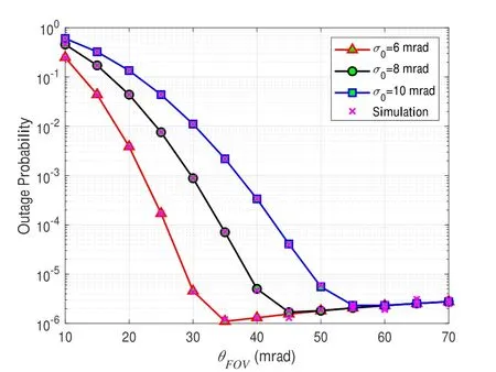
Figure 6. Outage probability versus FOV angle for varying orientation deviations(wz=2 m,Pt=25 dBm,σr=0.75 m).
The results for the outage probability versus the average optical power of the system under various atmospheric turbulence conditions are presented in Figure 7.The analytical results are in agreement with those of numerical simulation.It is evident that the outage probability decreases with an increase in the average optical powerPt,as shown in Figure 3.As expected,the outage probability performance is degraded with a deterioration in the turbulence conditions.This is because severe atmospheric turbulence conditions lead to a larger scintillation index and fast channel fading,resulting in a very high outage probability.Meanwhile,the atmospheric turbulence of theS-Rlink has more impact on the outage probability than that of theR-Dlink.For instance,whenPt=20 dBm,for theS-Rlink under weak turbulence,the outage probability is close to 3.3×10⁻⁴,while the outage probabilities are 3.5×10⁻⁴and 3.9×10⁻⁴for theS -Rlink under moderate and strong turbulence,respectively.
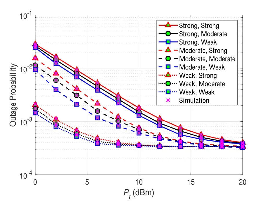
Figure 7. Outage probability versus average optical power for varying atmospheric turbulence conditions for the two FSO links (wz=2 m,θF OV=40 mrad,σr=0.75 m,σ0=10 mrad).
The influence of the beam waist and the average optical power on the outage probability of the relay system is demonstrated in Figure 8.The numerical and analytical results are closely matched.As expected,the outage probability decreases with an increase in the average optical powerPt,similarly to Figure 3.In addition,more optical beams are received aswzincreases.However,increasingwzalso means that the beam intensity becomes weaker and is limited by the average optical power,which raises the outage probability.For example,whenPt=15 dBm,the outage probability forwz=1 m is 0.028,compared with values of 1.3×10⁻³and 4.1×10⁻⁴forwz=1.5 and 2 m,respectively;however,the outage probability is 4.2×10⁻⁴atwz=4.5 m,which increases as expected to 4.5×10⁻⁴atwz=4 m.
The average BER performance for BPSK with varying values of the FOV angle and average optical power is illustrated in Figure 9.There is an exact match between the analytical and MC simulation results,which verifies the accuracy of our formulae.It can be observed that the average BER first declines and then slightly increases with an increase in the FOV angle.Moreover,the average BER shows an evident decrease for a largeθFOVwith an increase inPt.For instance,whenθFOV=70 mrad,the outage probability is 3.3×10⁻⁵atPt=10 dBm,which decreases as expected to 4.8×10⁻⁶and 7.8×10⁻⁷atPt=15 and 20 dBm,respectively.
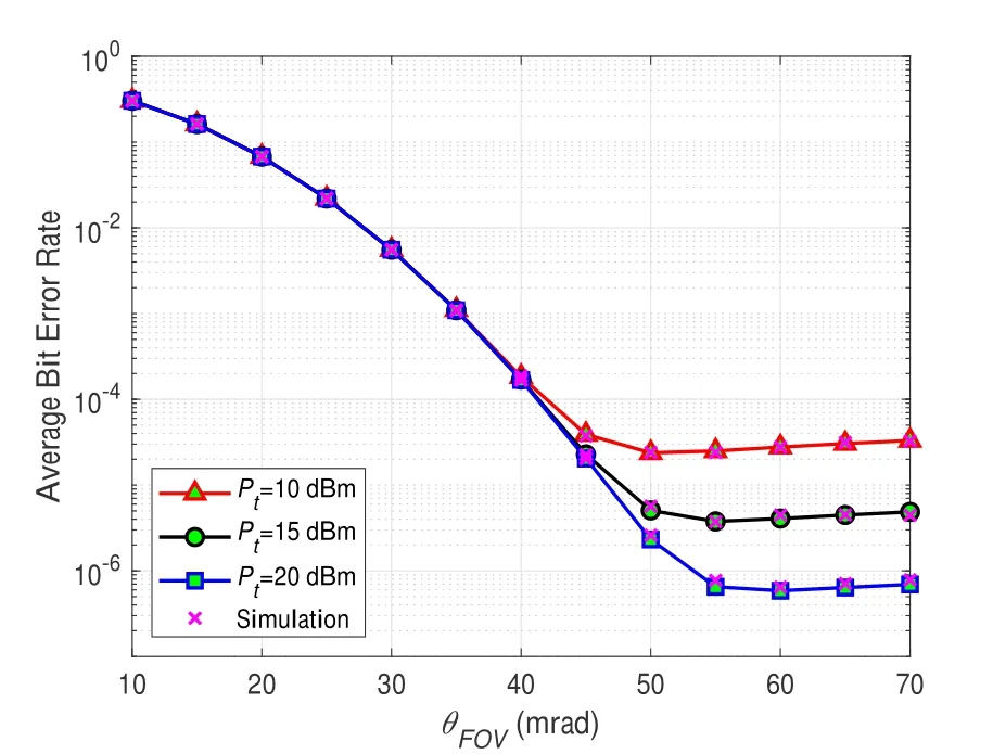
Figure 9. Average BER versus FOV angle for varying average optical power using BPSK(wz=2 m,σr=0.75 m,σ0=10 mrad).
Figure 10 illustrates the system performance by presenting the average BER for varying values of the average optical power and the orientation deviation under various binary modulation schemes.The analytical results are entirely consistent with their numerical counterparts.There is an increase in the average BER asσ0increases.With an increase inPt,the average BER first decreases and then approaches the asymptotic bound.The effect ofPton the average BER is similar to that of the outage probability,as can be seen from Figure 3.Finally,under the same conditions,the system with BPSK modulation outperforms the system with BFSK modulation at lowerPt,although these two modulation schemes tend towards the same performance with an increase inPt.For instance,forPt=5 dBm andσ0=10 mrad,the average BER for BPSK modulation is 2.7×10⁻⁴,which is smaller than the value of 3.5×10⁻⁴corresponding to the average BER for BFSK modulation.However,forPt=25 dBm andσ0=10 mrad,the average BER is 1.7×10⁻⁴using both BPSK and BFSK modulation.
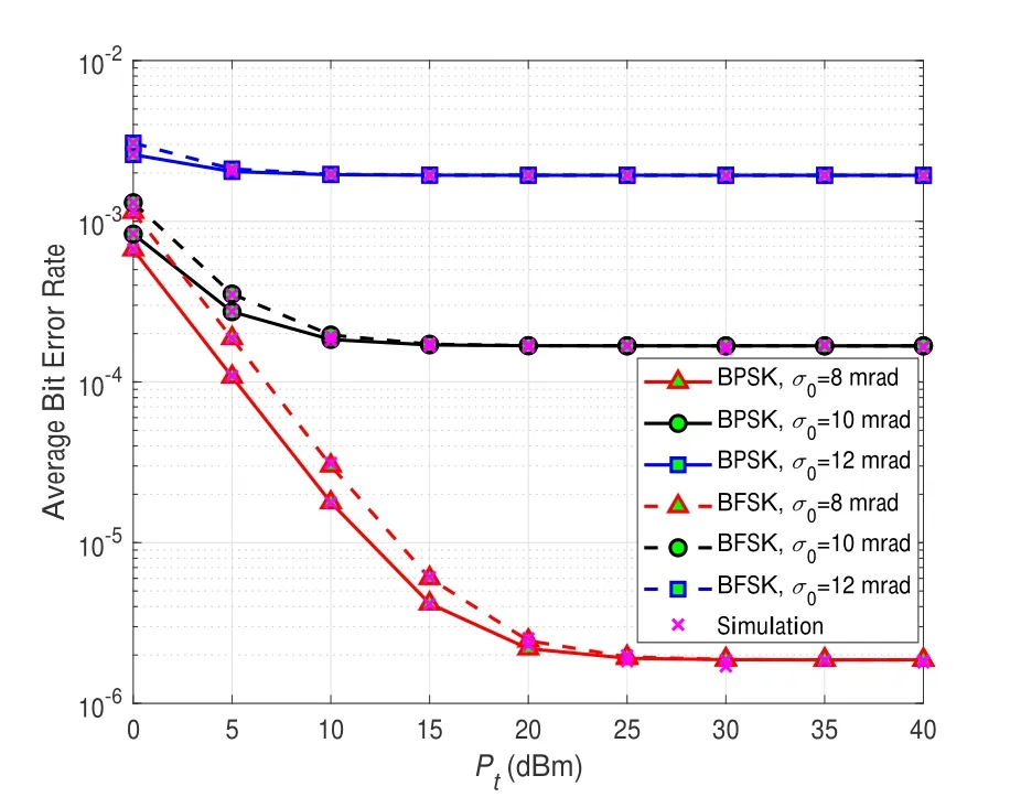
Figure 10. Average BER versus average optical power for different binary modulation schemes and orientation deviations(wz=2 m,σr=0.75 m,θF OV=40 mrad).
Figure 11 shows the average BER for the relay system versus the beam waist and jitter deviation.The color bar on the left side of the figure indicates the value of the average BER.As expected,decreasingσrcauses the average BER to decrease.For instance,whenwz=1 m,the average BER is 1.8×10⁻³atσr=0.5 m,which increases as expected to 0.023 and 0.082 atσr=0.7 and 0.9 m,respectively.In addition,whenσr <0.75 m,the trend in the average BER can be divided into two stages with an increase inwz.The average BER decreases with an increase inwzwhen the easily received beam dominates,but increases continuously with an increase inwz.It is worth noting that whenσr >0.75 m,there is no obvious variation in the average BER withwz >2 m.This is because the increase in the pointing errors becomes the dominant factor affecting BER.In the figure,there is an optimal point for the average BER,at whichwzandσrare 1.6 and 0.5 m,and the smallest average BER is 2.1×10⁻⁴.
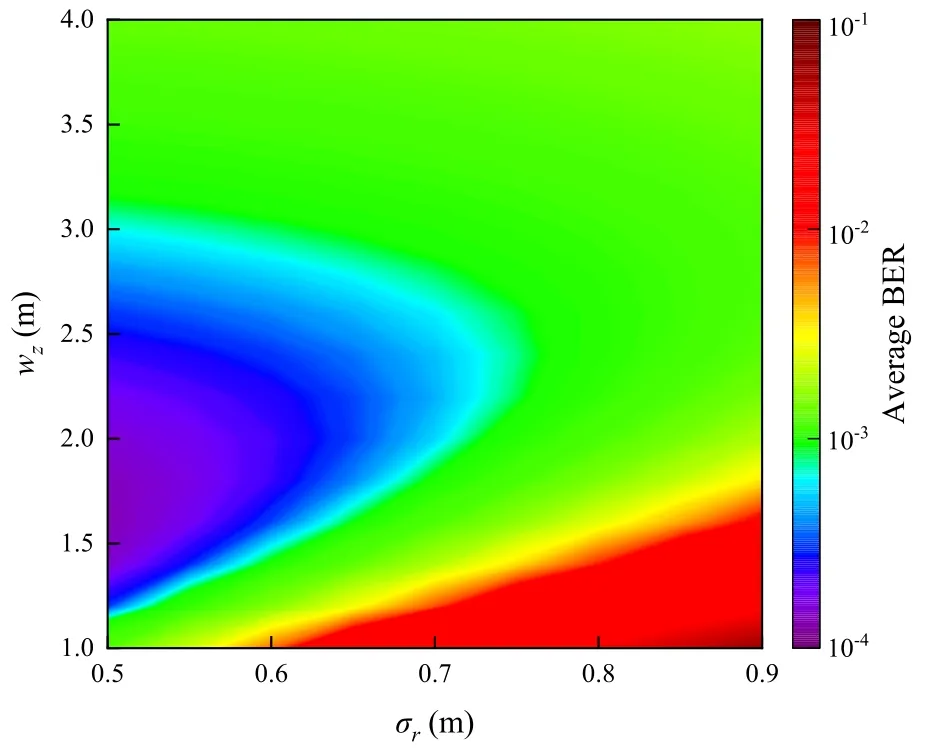
Figure 11. Average BER versus beam waist and jitter deviation(Pt=10 dBm,σ0=10 mrad,θF OV=60 mrad).
Figure 12 shows the ergodic capacity versus beam waist for different values of the jitter deviation.The simulation results provide a perfect match to the expression for the ergodic capacity in(39).Whenwzis small,more beams will be received aswzincreases;however,whenwzis large,increasingwzwill weaken the optical intensity and reduce the ergodic capacity.For example,whenσr=0.95 m,the ergodic capacity corresponding towz=0.5 m is 7.6 bits/s/Hz,compared with values of 14 and 18.4 bits/s/Hz atwz=0.7 and 0.9 m,respectively.Whenσr=0.95 m,the ergodic capacity is 21.5 bits/s/Hz atwz=3.5 m,which increases as expected to 22.7 bits/s/Hz atwz=2.5 m.With a decrease inσr,the ergodic capacity will increase.For example,whenwz=1.5 m,the ergodic capacity atσr=0.95 m is close to 22.7 bits/s/Hz,which can be compared with values of 23.6 and 24.4 bits/s/Hz forσr=0.85 and 0.75 m,respectively.
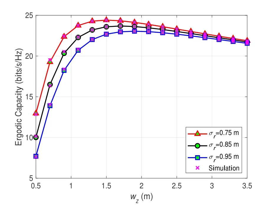
Figure 12. Ergodic capacity versus beam waist for varying jitter deviation(Pt=20 dBm,σ0=10 mrad,θF OV=35 mrad).
For more insight into the importance of the beam waist and FOV angle,we present the ergodic capacity versus the beam waist and FOV angle in Figure 13.The color corresponding to the ergodic capacity is illustrated in the bar on the left side of the figure.As expected,the ergodic capacity first improves and then deteriorates with an increase ofwz.With an increase ofwzandθFOV,there is performance improvement since the beam has a greater probability of irradiating the PD and being received.The decrease in ergodic capacity is due to the reduction in the beam intensity and the increased reception of background light noise with increasingwzandθFOV.It can be observed thatθFOVhas a significant impact on the ergodic capacity thanwz.The ergodic capacity is hardly affected by the value ofwzabove 3.5 m.This can be explained as follows: a suitable value ofwzprovides a larger ergodic capacity,but a bottleneck is encountered sinceθFOVis the dominant factor affecting the performance in terms of ergodic capacity.Hence,more attention should be paid to increasing the FOV angle of the UAV and decreasing the magnitude ofθFOVfrom an engineering design perspective.
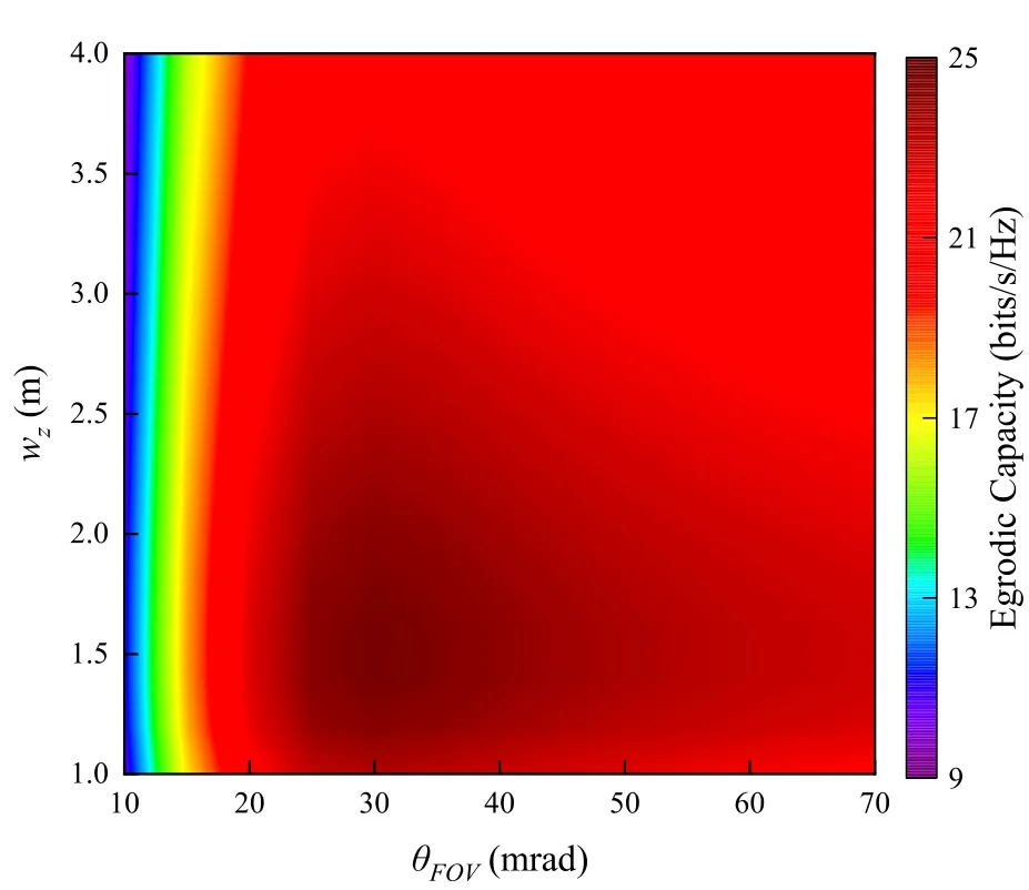
Figure 13. Ergodic capacity versus beam waist and FOV angle(Pt=20 dBm,σr=0.75 m,σ0=10 mrad).
Figure 14 illustrates the influence of the orientation deviation and FOV angle on the ergodic capacity.It can be seen that the ergodic capacity is sensitive to the values ofσ0andθFOV.One of the most significant phenomena is that a decrease inσ0can enhance the ergodic capacity.This can be explained by a decrease in the average value and variance ofθFOV,i.e.,and.As expected,an increase inθFOVinitially improves the ergodic capacity,but this then decreases.Whenσ0>10 mrad,the color changes obviously and rapidly asθFOVincreases from 10 mrad.For example,whenσ0=14 mrad,the ergodic capacity reaches 5.8 bits/s/Hz atθFOV=10 mrad,while the values of the ergodic capacity forθFOV=15,20,and 25 mrad are 10.9,15.7,and 19.3 bits/s/Hz,respectively,under the same conditions.Hence,a large value ofσ0represents strong AOA fluctuations,which can be effectively overcome by increasing the FOV angle of the UAV.
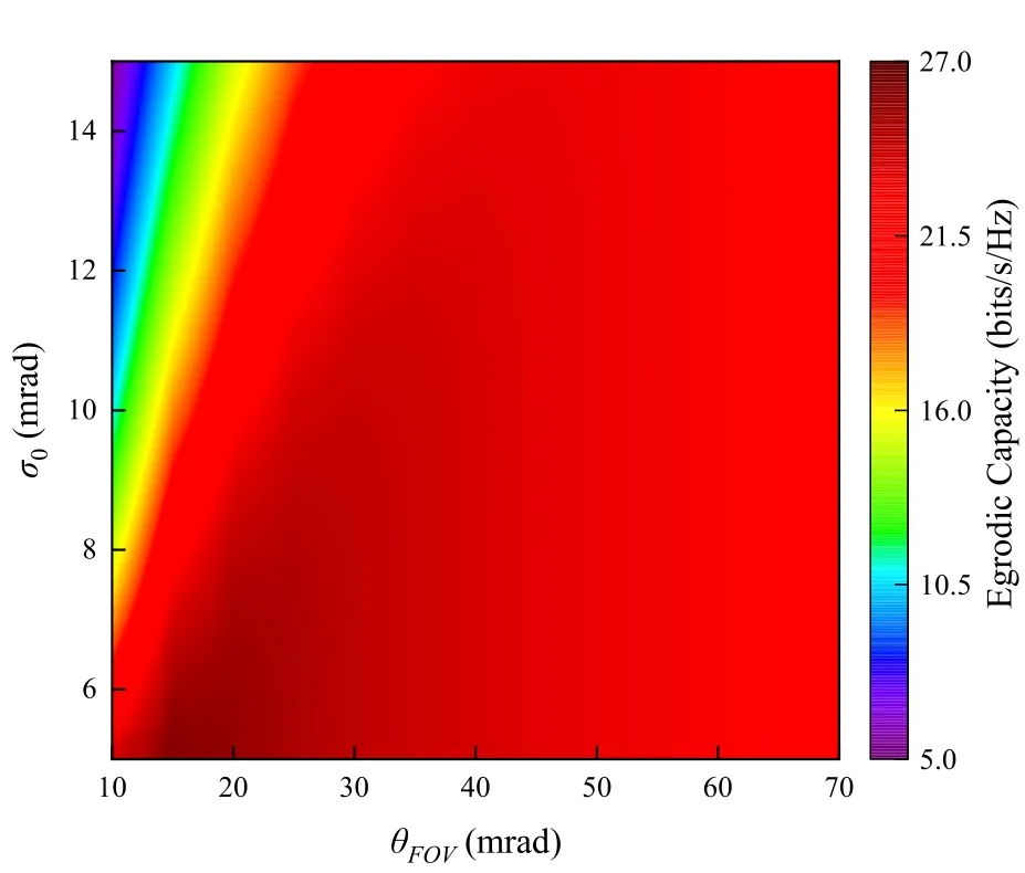
Figure 14. Ergodic capacity versus orientation deviation and FOV angle(wz=2 m,σr=0.75 m,Pt=20 dBm).
The practical implementation of the system requires two sets of FSO communication transceiver equipment.A transmitting device is used at the source,a receiving device is used at the destination,and the UAV is equipped with transceiver equipment.We expect several future research directions for this work.For example,to increase the flight operating time,the hovering UAV is replaced with a fixed-wing UAV,which requires us to consider the impact of the UAV trajectory and fly speed on the system performance.Another interesting work is to study multiple UAV relay systems for long-distance FSO communication.In addition,noise is one of the main factors limiting the system performance.
VI.CONCLUSION
In this paper,we have proposed a UAV-assisted FSO communication relay system with IM/DD detection under the AF protocol.For the source-to-UAV link,an accurate channel model was established by considering the impairments due to atmospheric absorption,pointing errors,Gamma-Gamma fading turbulence,and AOA fluctuations.The model of the UAVto-destination link considered attenuation due to atmospheric absorption,pointing errors,and atmospheric turbulence.Meanwhile,the M´alaga distribution was used to model atmospheric turbulence in the UAV-todestination link.Closed-form expressions for the CDF and PDF of the end-to-end system were derived,and closed-form expressions for the outage probability,average BER and ergodic capacity were obtained with the help of the EGBFHF.The perfect match between the MC simulation and analytical results proved the correctness of our performance formulae.In addition,we investigated the effects of system parameters(such as the average optical power,FOV angle,jitter deviation,orientation deviation,and beam waist) and atmospheric turbulence conditions on the system performance.Our simulation results showed that the impairments due to pointing errors and AOA fluctuations can be effectively compensated by an appropriate FOV angle and a beam waist.
APPENDIX
A Proof of End-to-End CDF
In this section,we derive the CDF for the end-to-end link for an instantaneous SNRγ.Substituting (19),(20),and(25),into(29),and using the definition of the Meijer-G function[32]and a substitution ofx=t-γ,we obtion(A.1),
whereC1andC2are thes-plane andv-plane contours,respectively.From[32],we know that
In order to facilitate the use of the EGBFHF definition,we use the substitutions=-s.From(A.2),the CDF forγcan be updated as(A.3).
Using the definition of the EGBFHF,the CDF forγcan be written as(30).
- China Communications的其它文章
- Secure and Trusted Interoperability Scheme of Heterogeneous Blockchains Platform in IoT Networks
- Intelligent Edge Network Routing Architecture with Blockchain for the IoT
- Privacy-Preserving Deep Learning on Big Data in Cloud
- PowerDetector: Malicious PowerShell Script Family Classification Based on Multi-Modal Semantic Fusion and Deep Learning
- Dynamic Task Offloading for Digital Twin-Empowered Mobile Edge Computing via Deep Reinforcement Learning
- Resource Trading and Miner Competition in Wireless Blockchain Networks with Edge Computing

