Interface bond degradation and damage characteristics of full-length grouted rock bolt in tunnels with high temperature
Yunpeng Hu, Mingming Zheng, Wenkai Feng, Jianjun Tong, Yiheng Wang,Qiling Wang, Kan Liu, Longzhen Ye
a State Key Laboratory of Geohazard Prevention and Geoenvironment Protection, Chengdu University of Technology, Chengdu, 610059, China
b Key Laboratory of Geohazard Prevention of Hilly Mountains, Ministry of Land and Resources (Fujian Key Laboratory of Geohazard Prevention), Fuzhou, 350116,China
c School of Civil Engineering, Southwest Jiaotong University, Chengdu, 610031, China
d College of Civil Engineering, Tongji University, Shanghai, 200092, China
Keywords:
ABSTRACT Full-length grouted bolts play a crucial role in geotechnical engineering thanks to their excellent stability.However,few studies have been concerned with the degrading performance of grouted rock bolts caused by extensive and continuous heat conduction from surrounding rocks in high-geothermal tunnels buried more than 100 m (temperature from 28 °C to 100 °C).To investigate the damage mechanism, we examined the time-varying behaviors of grouted rock bolts in both constant and variable temperature curing environments and their damage due to the coupling effects of high temperature and humidity through mechanical and micro-feature tests, including uniaxial compression test, pull-out test,computed tomography (CT) scans, X-ray diffraction (XRD) test, thermogravimetric analysis (TGA), etc.,and further analyzed the relationship between grout properties and anchorage capability.In order to facilitate a rapid assessment and control of the anchorage performance of anchors in different conditions,results of the interface bond degradation tests were correlated to environment parameters based on the damage model of interfacial bond stress proposed.Accordingly, a thermal hazard classification criterion for anchorage design in high-geothermal tunnels was suggested.Based on the reported results,although high temperature accelerated the early-stage hydration reaction of grouting materials, it affected the distribution and quantity of hydration products by inhibiting hydration degree,thus causing mechanical damage to the anchorage system.There was a significant positive correlation between the strength of the grouting material and the anchoring force.Influenced by the changes in grout properties, three failure patterns of rock bolts typically existed.Applying a hot-wet curing regime results in less reduction in anchorage force compared to the hot-dry curing conditions.The findings of this study would contribute to the design and investigations of grouted rock bolts in high-geothermal tunnels.
1.Introduction
Geotechnical rock bolts provide effective primary support and are widely used in underground engineering, such as mining and transportation tunnels(Moyo et al.,2012;Das et al.,2021).During excavation,the installed rock bolts significantly minimize the vault settlement and converging deformation of surrounding rock mass by clamping the weak rock strata,stabilizing the support structure and ensuring construction safety (Kaiser et al., 1992; Ren et al.,2010).However, with the rapid development of transportation engineering in complex geological conditions in West China,more and more tunnels were constructed in high geothermal environments (Gu, 2007;Hochstein et al., 2006; Hu et al., 2019).It is well known that rock bolts are tensile members working in deep rock and soil layers, where the heat from high-temperature rock or geothermal water can inevitably cause a series of physicochemical changes in the materials of the anchoring system, including water evaporation, hydration and hydrolysis of cementing materials.These changes will directly lead to the deterioration of the anchor solid bonding properties and structural damage, thereby weakening the durability and safety of the tunnel structure (Li et al.,2017a,b; Wang et al., 2018).
Generally, the anchorage system performance in tunnel construction is often significantly affected by surrounding rock characteristics, geological conditions, anchoring parameters, rod properties, and grouting material properties (Kılıc et al., 2002;Farhangi et al., 2020).In the past decades, researchers have conducted entensive experimental investigations on rock bolts.Hyett et al., (1992) performed field and laboratory tests and found that cement properties, embedment length, and radial confinement were the main factors influencing the bond strength of rock bolts.Ferrero (1995) performed the shear experiments on pre-stressed rock bolts and showed that the anchor parameters, such as rod size and component materials,significantly influence the rock bolt performance.The pull-out tests conducted by Kilic et al.,(2003)on rock bolts with cone-shaped lugs indicated that the shape of rock bolts was also responsible for the bolt deformation and loadbearing capacities.Aziz et al., (2008) conducted the laboratory tests to examine bonding capacity, rib spacing, and profile shape interactions.Thenevin et al.,(2017)conducted several pull-out tests on bolts and proposed a relationship between embedment length,confining pressure, and pull-out force.Furthermore, Delhomme et al., (2010) studied the joint constitution of long rock bolts cast in situ by laboratory pull-out experiments.The results showed that the bond strength between the bolt body and mortar was crucial only in transferring the initial tensile load because the concrete and anchor plate dominated the rest-stage tensile load transfer.Yokota et al.,(2019)studied the interface behavior of bolt-mortar through laboratory shear tests.Analysis of inner crack initiations and propagations showed that a decrease in the strength of bond materials attenuated the peak and residual strengths of rock bolts.Based on observation and analysis of these results,an investigation of the stress condition variation of anchor and distribution of axial force was conducted by Golewski (2018, 2019).Cui et al., (2020)found that appropriate bolt profiles are favorable to the support effect of the rock bolting system,but the interface shear behaviors need to be considered in concert.Zhang et al.,(2020)also reached the conclusion by conducting a series of direct shear tests on boltgrout interfaces, i.e.the peak shear strength and the deformation capacity of the bolt-grout interface are highly dependent on the grout mixture.The above research suggests that, as the main medium of force transfer in the anchorage system, grouting material properties play an important role in the performance of the anchoring effect.
Based on the above experimental findings, many theoretical studies have also been conducted,which shed light on the fact that mechanical properties of the interface affect the ultimate anchoring force greatly and are mainly governed by the properties of the stress transfer medium.Farmer (1975) presented an early theoretical solution for shear stress distribution along an anchor rod by studying the axial behavior of rock bolts subjected to tensile load.The results indicated that the interface shear stress between rock bolts and bond materials attenuated gradually from the loading point to the far end of the anchor rod.Li and Stillborg (1999)studied the elastic, softening, and debonding states of the anchorage system and developed analytical models for fully coupled rock bolts to address uniformly deformed and jointed rock masses.Based on the yielding design theory, stability analysis was performed by Larbi (2001) on reinforced rock slopes using two translational damage mechanisms to evaluate fully grouted passive rock bolts.Oreste(2008)proposed a new calculation procedure for analyzing the interfacial shear stress of fully grouted radial bolts in tunnels.Cao et al.(2014)presented a theoretical model to simulate rock bolt behavior by considering certain bolt-rod shape parameters.Ma et al.(2013) presented a new analytical model for studying fully encapsulated rock bolts, enabling the shear stress distribution and load-displacement curve to be calculated by relative formulations under certain tensile load amounts.Zou et al.(2021) developed a closed-form solution incorporating the nonlinear constitutive model for the interfaces between bolts and grout.Wang et al.(2022) proposed an improved shear-slipping model to describe the stress evolution characteristics of the boltrock interface, owing to which the mechanical properties of the interface can be fully considered in the anchorage design and verification.
Obviously, many scholars have done detailed research on anchorage performance and anchor design,but little focus has been placed on rock bolt performance in high-geothermal environments.Presumably, for full-length grouted rock bolts in high-geothermal tunnels, the surrounding rock, grout material and anchor body are the three main factors significantly affected by the objective environmental conditions of high temperatures.However,some scholars have proven that the effect of high temperatures on the physicomechanical properties of rocks, deep rocks in particular, is negligible unless the temperature exceeds 100°C(Peng et al.,2021).For rods made of reinforcing steel materials, Cadoni et al.(2021) found that the mechanical and thermal material parameters of reinforcing steel had little change up to 100°C.As for the grouting material,studies have shown that temperature rise can cause microcracks and thereby decrease the strength(Lin and Meyer,2009;Wang and Lee,2012).According to Cui et al.(2015) and Ma et al.(2015), the bond strength of cement first increased and then decreased with temperature rise, indicating an adverse effect of high temperature on interfacial strength.Some scholars investigated the association between temperature and anchor pull-out properties(Li et al.,2017a,b;Wang et al., 2018) and identified the attenuation behavior of interfacial shear strength.Thus,the grout itself and associated interfacial mechanical response were the key factors in the performance of anchored structures.It is worth noting that these studies were carried out in constant-temperature contexts.However, according to the results of the latest field tests on high-geothermal tunnels,support structure materials near the excavation surface are generally exposed to changing temperatures (Wang et al., 2019a), which is a fact previous scholars have rarely considered.Furthermore,technical practices have demonstrated that high-geothermal tunnels typically caused hot-humid (in the presence of large amounts of fissured water) or hot-dry environments (Cui et al., 2017, 2018).Hence, the mechanical properties and failure characteristics of the anchorage system within a rock layer were inevitably influenced by relative humidity(RH)(Wang et al.,2019b).The ultimate pull-out force and failure characteristics of rock bolts under a high temperaturehumidity coupling effect will certainly be different from those under normal tunnel engineering practices.
In summary, the grouting material will undergo a series of physico-chemical reactions different from those in the conventional environment, resulting in large changes in the mechanical properties and bonding performance of the anchor solid.Although some investigations on the characteristics of drawing force and interfacial bond strength of anchorage systems under normal environment have been reported,consideration is yet to give to the effect of high temperatures on the performance of the anchoring materials and anchoring system.Particularly,the grouting material used in actual high-geothermal tunnels was hydrated and solidified under variable temperature curing (VTC) conditions instead of constant high-temperature curing conditions.In addition to the problem of high temperature, the influence of RH in highgeothermal tunnels on anchorage performance should not be underestimated because the combined effect of temperature and RH cannot be ignored.
Driven by the revealed gaps in the literature, a series of laboratory tests on grouting materials and grouted rock bolts under different temperatures(40°C,60°C and 80°C),RHs(25%,55%and 95%), and curing ages(1, 3, 5,14 and 28 d) were conducted in this work.The microstructures of the bolted specimens were measured through scanning electron microscopy (SEM), X-ray diffraction(XRD), thermogravimetric analysis (TGA), and computed tomography(CT).The influence of the coupling effect of high temperature and RH on interfacial bond degradation of full-length grouted bolts was studied,and three typical failure modes and cracking evolution of rock bolts in high-geothermal tunnels were proposed and discussed.Based on the experimental results,a new damage model of interfacial shear-slip of the anchoring system considering environmental coupling effects was proposed.For a theoretical optimal design and engineering application of fully grouted rock bolts for high-geothermal tunnels, a new design method considering heat damage classification and evaluation was presented.
The shear failures in rock bolts in high-geothermal tunnels are catastrophic in nature and are worthy of attention.The extent of the bonding damage at the interface due to the high geothermal environment and its consequences on the behavior of the anchorage structures must be established as part of the preliminary analysis to determine the reliability of the existing structure.A large number of engineering practices have proven that anchors in high-geothermal environments suffer from a lack of pull-out resistance and a decrease in overall support performance.Numerous investigations have been done on the anchorage performance and anchor design of rock bolts under conventional environments.However, there are few studies on the anchoring performance of anchors in high-geothermal environments in the literature, and there is also a lack of systematic and unified theory that can be directly used in engineering practice.In this research,the unique high and variable-temperature curing environment in high-geothermal tunnels is fully considered.Due to the influence of cooling measures in tunnel construction,the curing temperature of the anchoring material in the hydration process is not constant.Furthermore, this paper compares the effect of different curing conditions on mechanical properties of anchoring materials,especially the temperature-humidity coupling effect on the anchorage performance.The findings are universal and applicable to both hot-dry and hot-wet environments of high-geothermal tunnels.The research results of this study are based on conventional cement-based materials without special chemical additives.Accordingly, the optimization of the anchor structure design method based on ordinary Portland cement extends the applicability of the reported outcomes.In this regard,an in-depth study on the damage mechanism of full-length grouted rock bolts for highgeothermal tunnels can provide guidance on controlling the curing environment during the construction of anchors.In addition,based on the anchor structure damage model proposed in this paper, it is possible to carry out a quantitative evaluation of the mechanical properties of anchor materials and the evolution of anchor structure support performance under different maintenance regimes easily and quickly, which helps to optimize the design method of rock bolts for high-geothermal tunnels.Therefore, the study on the rock bolt with full consideration of realistic environment characteristics of high-geothermal tunnels is critical and necessary.The theoretical and experimental research to ensure the safe application of anchors and to improve anchoring design methods under high-geothermal environments is of strong economic importance and technical guidance.
2.Test conditions and procedures
2.1.Specimen design
2.1.1.Grouting materials
According to the design of one typical high-geothermal tunnel,we used an M35 cement mortar as the grouting material for the rock bolt during the laboratory test.A commercial Portland cement called Xinan was adopted, whose strength grade was 42.5.The specific gravity was 3.15 kg/m3,the fineness modulus was 2.54,and the mixing ratio was water:cement:sand=0.5:1:1.No admixtures were used in the grouting material in our test.Table 1 lists the chemical composition of the cement.
2.1.2.Rock specimens
The rock specimens were taken from the high-temperature section of a certain tunnel construction site.The lithology was granite with gray-white in appearance, and the main components were quartz, feldspar, biotite and amphibole.First, the mechanical parameters of the rock sample were tested.The rock was cut off and polished into cylinder specimens with a diameter of 50 mm and a height of 100 mm for the uniaxial and triaxial compression tests.The mechanical parameters of the test granite are listed in Table 2.Then, the rock specimens for the anchor system were formed into 100 mm × 100 mm × 100 mm cubes, and the diameter of the borehole in the rock sample was 42 mm (Fig.1).

Table 2 Mechanical parameters of granite.
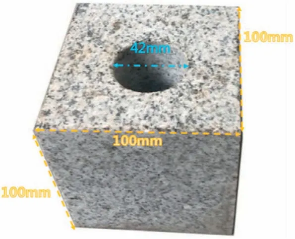
Fig.1.Granite sample for rock bolt pull-out test.
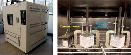
Fig.3.External and internal pictures of specimen curing device.
2.1.3.Anchor rod body
For the rock bolt pull-out tests,we used the HRB400 hot-rolled ribbed bars of 22 mm in diameter,as shown in Fig.2.The steel bar had a total length of 320 mm and an anchorage length of 100 mm.According to the normal tension tests, the yielding and ultimate tensile strengths of the anchor rod were 451.2 MPa and 585.7 MPa,respectively.
2.2.Testing apparatus
2.2.1.Sample curing device
The curing test equipment was HX/HS-010L with a steady temperature and humidity test chamber.The temperature can be regulated in the range of 0-150°C, and the maximum RH adjustment was up to 98%.The adjustment precision of the temperature and RH parameters were 0.1°C and 0.1%,respectively.The variation of environmental factors can be determined by an internal servocontrol system (Fig.3).
2.2.2.Mechanical testing apparatus
The pull-out test was conducted by a hydraulic universal testing machine and a special drawing device.The maximum test force of the machine was 10 kN,and the moving speed of piston can be set below 100 mm/min.Fig.4 shows that the special drawing device consists of a bearing plate(upper and lower),a ball joint rod,a rigid cushion block, and a connecting rod.The bearing plates were connected by four connecting rods to form a steel frame, and the holes were made both in the center of the upper and lower bearing plates.The ball joint rod passed through the upper bearing plate and was clamped by the chuck of the universal testing machine to help improve the situation of eccentric tension.The stiffness of the cushion block was large enough to avoid elastic deformation under greater external pressure.The center of the cushion block was provided with a hole, whose diameter was larger than that in the rock specimen,to ensure the free slip of the anchorage component.As the tester beam moves vertically upwards,the anchorage body is pulled out slowly.The test device is shown in Fig.7, an electronic micrometer (range <12 mm) was installed and fixed in the center of the anchor rod to test the displacement of the anchorage body in the free end.The loading test was controlled by equal strain speed(0.00025 s-1), and the load rate was kept at a constant rate of 0.5 mm/min.The changes of load and displacement in the loading end were auto-monitored by a computer.The loading test was stopped either when the descent part of the test curve flattened out or the test result exceeded the range of the electronic micrometer.
2.2.3.Microstructural testing equipment
As seen in Fig.5,microcosmic experiments of grouting material were performed on the scanning electron microscope JSM-7800F.The scanning angle was between -7°and 70°and varied between 25 and 1000,000 in magnification, with a resolution between 1.2 nm and 0.8 nm.The Empyrean X-ray diffractometer produced by Marvin Panaco was used for the XRD test.The detector counting matrix inside the equipment was 256 × 256 pixels.The goniometer radius was 240 mm, and the measuring angle range was -110°-168°.The Mettler Toledo TGA/DSC3+ synchronous thermal analyzer was used in the TGA.The range of temperature control was room temperature to 1100°C or room temperature to 1600°C.The sensitivity of the weighing balance was 0.01 μg.The calorimetric temperature resolution was 0.00003°C with 6 PT/Rh thermocouples,with a calorimetric accuracy of 1%.The device used in this test was Siemens SOMATOM Definition with multiple helices.The scanning range of the machine with high resolution was 200 cm.The detector was capable of collecting 64 layers of 0.6 mm thin layers, with the fastest scanning speed being 0.33 s per 360°.
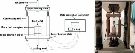
Fig.4.Schematic diagram and photo of the rock bolt tension device.
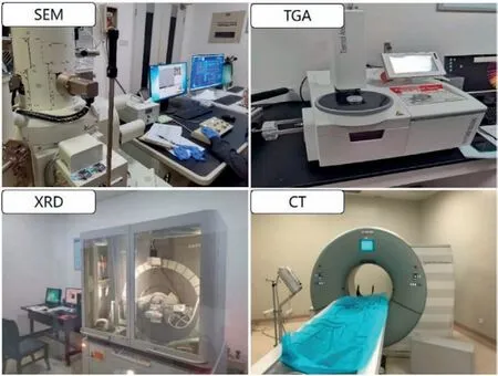
Fig.5.Microscopic testing equipment of anchoring system.
2.3.Test environment and scheme
2.3.1.Test procedure
Two mechanical experiments were performed for this study.One was the mechanical experimental investigation of the grouting material.Fig.6 shows the formation of the cube specimens in the mold on a vibrating table to ensure that the cement mortar tightly filled up the mold undetached.According to the test specification GB/T 50448-2015 (2015), the arithmetic mean of the measured values of the three specimens was obtained as the specimens’compressive strength.The second experiment was on the mechanical characteristics of rock bolts under drawing load.First,the grouting material was carefully poured into a 42-mm diameter hole.Subsequently, the rock bolts were slowly inserted into the borehole center.After setting the cement mortar, the finished products were kept in a curing chamber.All the grout specimens were simultaneously cast and bolted for the compression test.Finally,the prepared rock bolt samples were installed with a special drawing device in a hydraulic universal testing machine.
Furthermore, the failure mechanism and patterns of rock bolts in high-geothermal environments were investigated by considering the mechanical properties of the grout body and anchor structure and through microscopic characteristics tests on samples under hot-dry and hot-humid conditions.The tests included SEM,XRD and TGA on the grouting material as well as non-destructive CT scanning on the anchorage specimens.
2.3.2.Curing regimes
Curing condition is a factor that significantly influences the mechanical properties of cement-based materials.As confirmed by pioneer studies, curing is a necessary step to reach the acceptable compressive strength (Cho et al., 2017; Borrero et al., 2021).For instance, outdoor curing enhances the permeability of concrete specimens, and the maximum strength for curing at high temperatures can be achieved at early ages(Hassan et al.,2021).For studies on the grouting materials used in high-geothermal tunnels,there are three types of curing regimes to be considered, which are constant high-temperature curing condition, standard curing (SC) condition and VTC condition.The constant high-temperature curing regime is not in line with the actual environment of high-geothermal tunnels because it greatly accelerates the evaporation of water inside the cementitious material and affects the continuous hydration reaction process.The experimental results using the scheme are expected to be close to that cured under hot-dry environment (Bohloli et al.,2019).Based on our previous study and the research results of other scholars(Hu et al.,2020,2021),the VTC regime strengthens the specimens greatly at the early stage but can result in low ultimate strength of specimen at the late stage compared to the SC regime.Direct use of anchor material parameters obtained by a SC regime can inevitably result in large deviations in the anchorage design.
According to the results of previous field tests, the typical geothermal temperature of tunnels is above 50°C,and considerable differences exist in the RH distribution because the water conditions vary greatly from case to case.Therefore, three different temperature conditions (40°C, 60°C and 80°C), three RH levels(25%,55%and 95%),and five curing ages(1,3,5,14 and 28 d)were considered as test conditions in the present work for studying rock bolt performance in high-geothermal tunnels, and the specimens for the tests were cured using VTC method.Fig.7 shows the variable temperature curves of the tests.Notwithstanding, for comparative analyses,we also tested some specimens cured under SC conditions (20°C and 95%).Table 3 summarizes the experimental conditions.
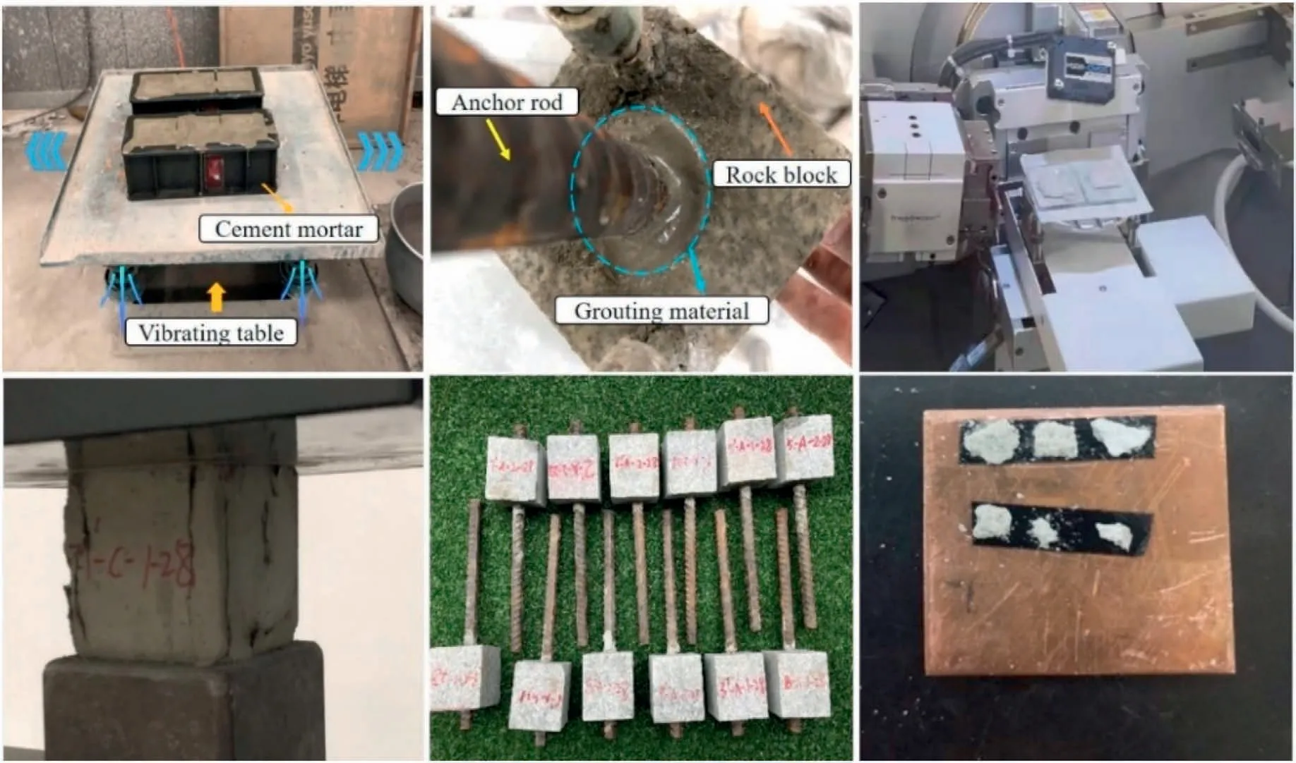
Fig.6.Manufacturing and testing of specimens.
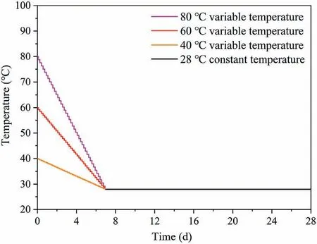
Fig.7.Relationship between curing temperature and curing time.
3.Experimental results and discussion
3.1.Mechanical properties of grouting material
A comparison of mechanical properties of grout body cured under SC (Fscu) and VTC (F′scu) showed that a high curing temperature significantly improved the early strength of the grouting material specimen,particularly at the curing age of 1-5 d.However,the strength increase rate slowed down after the 5th day.The longterm strength of the specimens cured for 28 d was less than that cured under the SC condition (Table 4).For example, Fig.8 shows that the compressive strength of the grouting material samples under 40°C-95%-VTC, 60°C-95%-VTC, and 80°C-95%-VTC were28.3 MPa, 26.4 MPa, and 24.1 MPa, which were 36%, 27%, and 16%greater than their counterparts under the SC condition, respectively.Typically, when the curing age was 1 d, the strength of the grouting material specimens under 80°C-VTC was four times higher than that of the common samples.The higher the curing temperature,the more the strength increased within 3 d.However,the trend of the experiment reversed when the curing age reached 28 d.The compressive strength of the grouting material samples under 40°C-VTC, 60°C-VTC, and 80°C-VTC was 8%,14%, and 28%less than that under the SC condition, respectively.Thus, a significant crossover effect (Yang et al., 2015; Castellano et al., 2016) on strength of grouting material is observed.The reason for the phenomenon is that a compact protective shield would be formed on the surface of the cement particles and inhibit the hydration reaction if the grouting materials keep hydrating at a faster rate under high-temperature conditions.Even with an increase in curing age,the hydration response would be sustained at a lower stage,decreasing the long-term intensity(Elkhadiri et al.,2008;Teymen,2017; Wang et al., 2020).As a result, samples of grouting material cured at high temperatures showed opposite trends in initial compressive strength and later strength.Thus,though the samples cured under lower-temperature conditions had lower initial strengths,they could grow much stronger at the late stage.Similar results were obtained under the RH of 25% and 55%.
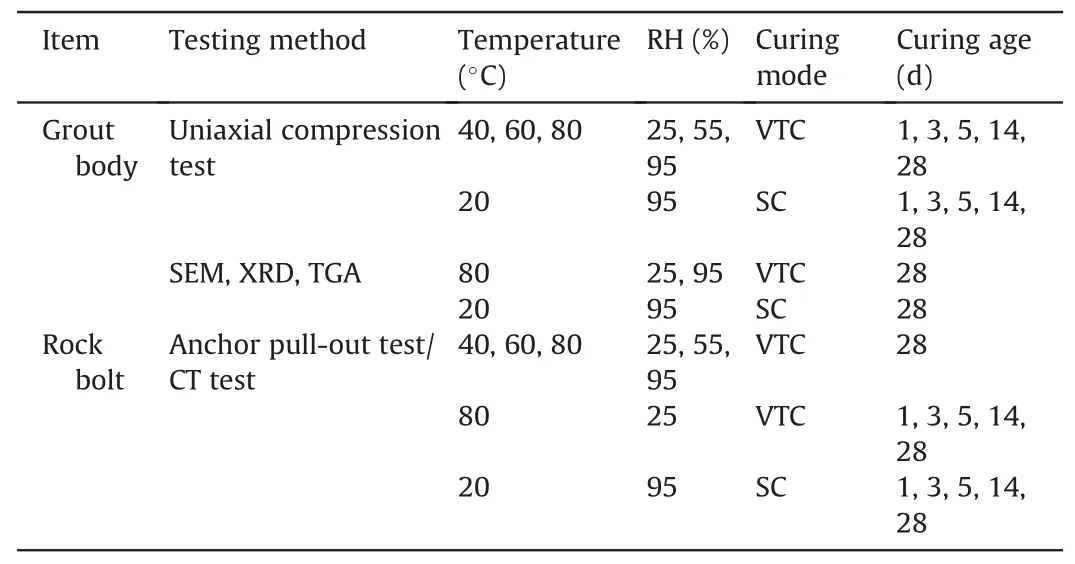
Table 3 Experiment details.
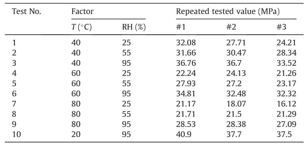
Table 4 Test conditions and results of specimens at 28 d.
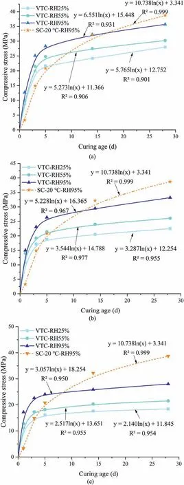
Fig.8.Coupling effect of temperature and humidity on compressive strength of grout:(a) 40 °C, (b) 60 °C, and (c) 80 °C.
The compressive strengths of specimens cured for 28 d were selected for statistical analysis (Table 5).There were 9 sets of specimens with a total of 27 measured values under different curing conditions.Experimental results indicated that the deviation of maximum and minimum values from the middle value was less than 15%, meeting the requirements of the test specification GB175-2007(2007).The total standard error was close to 1,which proved that the mean error of the test was small (Dabiri et al.,2022).The mean of the representative strength values for the nine sets of data was 27.1 MPa with a standard deviation of 5.648 MPa.The large dispersion of the data suggested that the compressive strengths of the specimens were greatly influenced by the curing conditions.Compared to specimens cured under standard conditions,the compressive strengths of grout samples under VTC conditions were reduced by an average of 30%.For the coupling effect of temperature and RH on grouting material, the experimental results indicated that RH had a varying effect on the early and late-stage strengths of the grouting material samples cured under VTC conditions.For the early strength, the compressive strength of the grouting material increased with increasing curing humidity in all test conditions.For instance, at 40°C, a growth range occurred from 44%to 75%for the compressive strength of the samples within 5 d when the RH increased from 25% to 95%.Moreover, as the curing temperature increased, the growth rate reached a maximum of 92% at 80°C-3 d, indicating that the rapid increase in initial strength caused by humidity was more significant under a higher curing temperature.For the long-term strength of the grouting material specimens, a high RH reduced the strength loss caused by a high curing temperature.Compared with the test samples cured under the SC-28 d condition, the compressive strength of the specimens cured under 40°C-95% fell by 7.8%,whereas that of specimens cured under the 40°C-25%condition fell by 27.7%.This result indicates that a higher humidity may provide sufficient free water for the hydration reaction and reduce strength loss due to moisture evaporation under a high curing temperature(Wang et al., 2017).Although the late-stage compressive strength decreased at 28 d, the degradation slowed down when the water was sufficient.However, when the temperature was set at 80°C,the loss of intensity was above 30%under different humidity levels,meaning that hot and dry environments were inconducive for the development of the grouting material strength.
3.2.Anchoring performance of rock bolts
3.2.1.Characteristics of deformation damage
(1) Typical failure patterns
The ultimate tensile strength of full-length bonded rock bolts mainly depends on the component material and interface bondstrength (Fig.9), including the strength of the rock bolt body and rock mass, the bond strength between the rock bolt and grouting body(first interface),and the bond strength between the grouting body and rock mass (second interface).Different failure modes of rock bolt samples occur under different conditions.For the rock bolt system in a high-geothermal tunnel,high temperature and RH have little impact on the strength of the rock bolt body and rock mass.However, the development of the mechanical properties of the grouting material,as a transfer medium for external forces,in a high-geothermal environment significantly influences the failure modes of the rock bolt system.

Table 5 Statistical analysis on compressive strength of grouting materials.
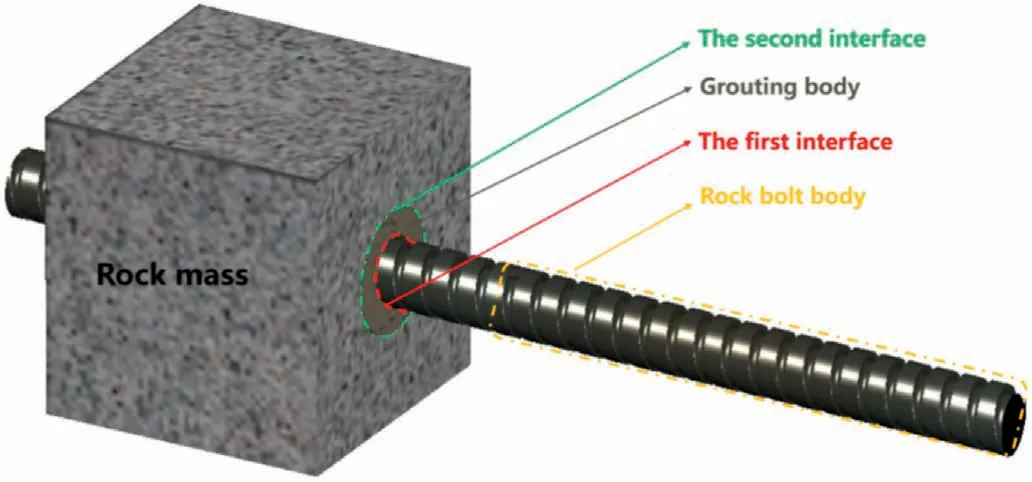
Fig.9.Failure position of rock bolt under drawing force.
To investigate the internal failure characteristics of the anchorage system, we created cross-section drawings of the specimens according to the pull-out tests.Three typical failure patterns were obtained under the conditions of this study.As can be observed from Fig.10a,when the external pull-out force transferred from the anchor rod body exceeded the bond strength of the first interface, the bolt body slipped out along the first interface, and a small amount of cement was left near the longitudinal rib.Scratches were observed on the surface of the extracted anchor bars.For the failure mode F1,the chemical bonding strength of the first interface between the anchor rod and grouting body was the major pulling resistance component.
When the strength of the grouting material was sufficiently high and the interfacial combination between the anchor rib and grouting body was enhanced, the external pull-out force was transferred to the second interface from the compound system assembled by the anchor rib and grouting material.The grouting body then slipped out along the interface between the rock mass and grouting material when the shear stresses exceeded the bond strength at the second interface.Fig.10b shows many scratches on the side surface of the grouting body in the failure mode F2.The failure process of the anchorage system was mainly influenced by the chemical bonding strength and friction.
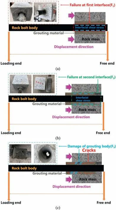
Fig.10.Characteristics of damaged anchor structure: (a) Failure mode F1, (b) Failure mode F2, and (c) Failure mode F3.
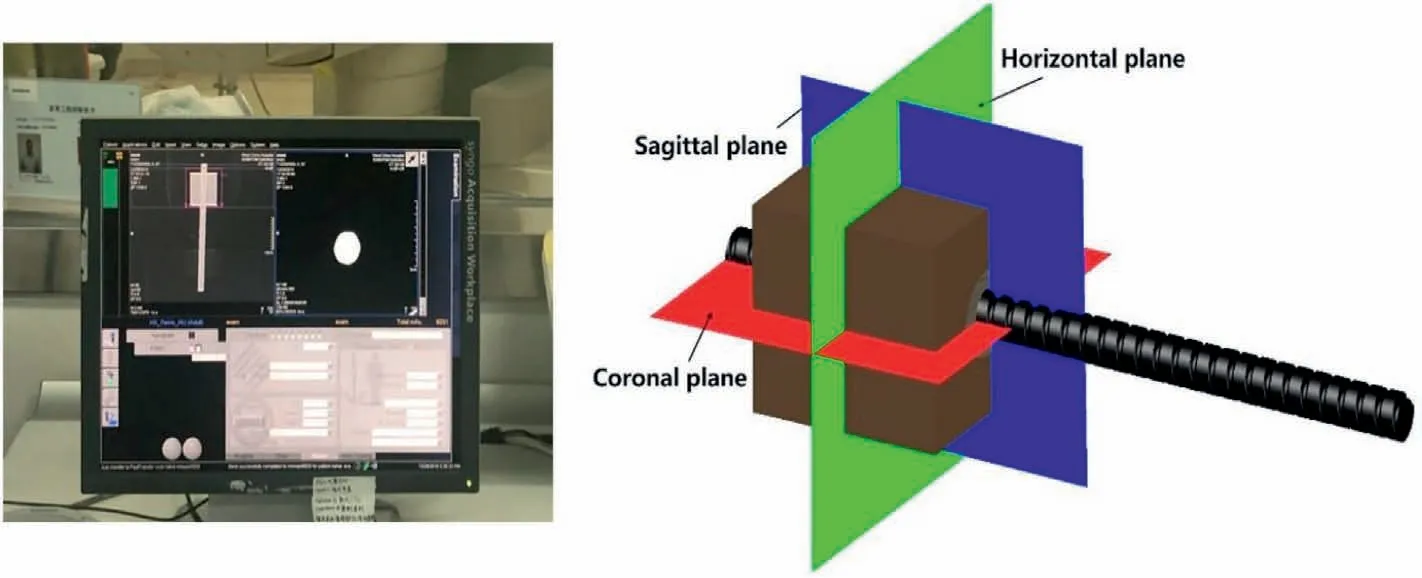
Fig.11.Schematic diagrams of CT scan layers and relative positions of each tomography.
The stress distribution of the grouting body was complicated as the body was the main carrying and passage medium of the pullout force between the first and second interfaces.Fig.10c shows that the fracture surface had an irregular shape while massive residual grouting blocks were left on both the rock mass surface and anchor rod.The filling uniformity, hydration degree, and contact tightness of the rock mass with the grouting material significantly influenced the fracture failure location in the failure mode F3.For the tensioned anchors, more cracks appeared where stress was concentrated, and the anchorage system was broken when the shear stress or tensile stress produced by the applied load exceeded the limit strength of the grouting material.
(2) Analysis of CT scanning results
To verify the real damage characteristics within the anchorage material,we scanned specimens of three typical failure patterns by CT and plotted the results using rainbow holography and pseudocolored enhancement technology.Horizontal and coronal sections of the samples were selected as the analysis objects (Fig.11).
The CT images contained four main components: anchor ribs,cement mortar,granite,and air.The interfaces between anchor ribs and cement mortar and that between cement mortar and granite were clearly visible.A circular blue cement mortar was observed around the anchor ribs,as well as numerous visible bright spots on the grouting body, representing the denser sand in the cement mortar.Under the tensile load, cracks developed in the cement mortar and appeared as pink filaments in the CT image(Fig.12).
Fig.12a (failure mode F1) shows that the pink area around the bolt is almost completely connected in the horizontal plane.In the coronal and sagittal sections, the rock bolt body and grouting material are separated, and the relative displacements appear at the same time.This phenomenon indicates that the shear stress is concentrated on the first interface and at the loading end under a large drawing loading.The cracks appeared and developed gradually from the anchor head to the deep of the anchorage system,resulting in disengagement at the interface of the anchor rod and grouting body.The relative slip between the grouting material and anchor rib indicates that the friction and mechanical interlocking(between the ribs and screw) on the first surface provided pulling resistance.
The CT scanning results in Fig.12b demonstrate that a few cracks occurred in the internal structure of the grouting material in the horizontal plane.The coronal and sagittal planes present an entirely composite structure.Thus,for the failure mode F2,the bond strength between the rock mass and grouting material was the main initial pull-out resistance.However, the friction occurred on the second interface during a relative sliding trend between the anchor solids and rock mass due to the roughness of the rock mass surface and radial expansion caused by the expansion effect.Subsequently, some of the grout debris produced by the shear stress damage remained on the rock surface, and the relative slip of the anchor solids occurred.
Fig.12c illustrates the cracking characteristics of the failure mode F3.From the horizontal plane, many cracks emerge in the grinding body and distribute unevenly.The coronal and sagittal planes indicate that the grouting body initially moved slightly toward the loading end and finally split into two from the middle.Thus,the bonding strength between the grouting material and rock mass was greater than the ultimate strength of the grouting body.The CT scanning results showed many discontinuous cracks in the grouting body,and the cracks extended from the loading end to the free end.When an external pull-out force passed through the broken grouting body with poor integrity,the grouting material at the loading end of the specimen was damaged under the effect of radial extrusion and longitudinal stretching, resulting in an incomplete grouting body after pulling out.
3.2.2.Mechanical behaviors
(1) Ultimate tensile force
The ultimate pull-out force (Fp) of each group of specimens obtained from the test was averaged,and the results are shown in Table 6.When the age of rock bolts were 28 d, the curing temperature and RH had opposite effects on Fp(Fig.13).As the curing temperature rose,the ultimate tensile force decreased significantly,especially between 40°C and 60°C.Compared with the samples cured under SC condition,Fpdecreased by 2.7%,23.1%,and 38.1%at 40°C,60°C,and 80°C,respectively(RH=95%).Moreover,sharper downturns were observed in Fpas temperature increased under lower RH values, with the maximum drop being 69% at a curing condition of 80°C-25%.However,a high curing temperature did not always result in a high attenuation of Fp.For example,when the RH was below 55%, the temperature rise from 60°C to 80°C only caused a 9.8%-10% decline in Fp.As illustrated in Fig.14, Fpincreased with increasing RH.A higher RH inhibited the crossover effect.When the curing temperature was set at 40°C,the increase in Fpcaused by humidity growth was 116%,whereas it was 102%at 80°C.Thus, a higher curing humidity had a positive influence on the development of Fp,but with the rise in curing temperature,the growth of the pull-out strength at 28 d seemed to slow down even under a high RH.
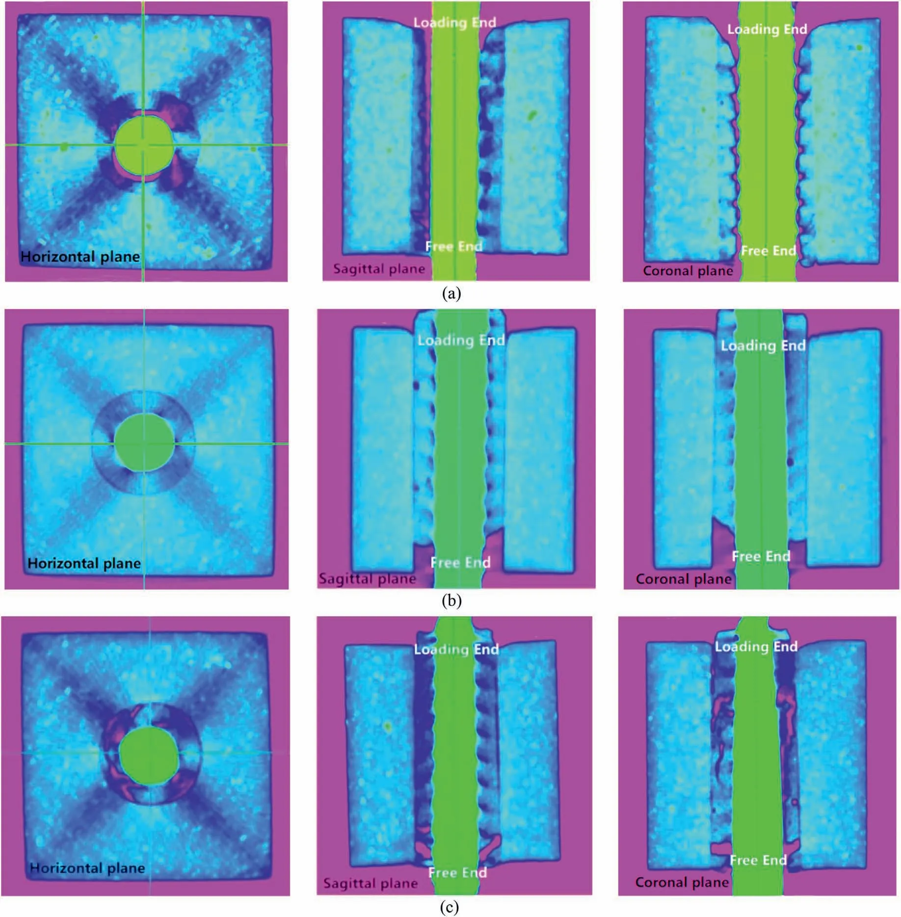
Fig.12.CT scan images based on pseudo-color enhancement: (a) Failure mode F1, (b) Failure mode F2, and (c) Failure mode F3.
(2) Average bond strength
The anchorage length of the rock bolt designed for the laboratory test was shorter than that of the on-site bolt.We assumed that the bond stress was uniformly distributed along the anchorage length.Calculation results of τ based on Eq.(1)were selected as the average bond strength of the corresponding interface.
where L is the anchorage length of the rock bolt, P is the tensile load,π is a constant,and π is the diameter of the anchor solid.For failure mode F1,Diis equal to the bolt diameter.For failure mode F2,Diis the diameter of the drilling hole.For failure mode F3,Diis the mean value between the rock bolt and the drilling hole.Considering the different failure modes of samples cured under different temperature and humidity conditions, the peak bond strength () and residual strength () are listed in Table 7.
(3) Peak bond strength
Temperature and RH affect peak bond strength Fpsimilarly.The peak bond strength of the specimens cured under the VTC condition was lower than that of the specimens cured under the SC condition at 28 d.The peak bond strength of the anchorage system decreased linearly with an increase in the initial curing temperature but was inversely proportional to the humidity (Fig.15).
For damage mode F2,the magnitude of the peak bond strength mainly depended on the chemical adhesion between the grout and hole wall at the second interface.For damage mode F3, the magnitude of the peak bond strength mainly depended on thesplitting resistance of the grout itself.Under the VTC condition,although high temperature enhanced the early grout strength and chemical adhesion with the pore wall,the rapid hydration reaction generated hydration products that lapped hastily, causing the structure and cementing surface to be loose and porous.The generated hydration products adhered to the surface of the cement particles,which hindered the hydration reaction process,reducing both the strength of the grout itself and the chemical bonding strength with the pore wall at a later stage.Higher curing temperatures increased the strength degradation.Thus, the ultimate pull-out force of the anchorage system decreased with an increase in curing temperature.The increase in humidity promoted the continuous and efficient hydration reaction of cement, which enhanced the strength of the grout itself and the chemical adhesion with the interface.Consequently,the ultimate pull-out force of the anchor system increased with an increase in curing humidity.

Table 6 Test results of ultimate pull-out force under different conditions.

Table 7 Experimental results of average bond strength.
(4) Residual bond strength
The influences of curing temperature and humidity on the residual bond strength was related to the failure mode.Environmental conditions had less influence on the residual strength of the samples (such as 40°C-55% and any T°C-95%) in failure mode F3.The residual strength of the specimen in this destruction mode was mainly determined by the frictional resistance of the interface when relative sliding occurred.As the wall of the test boreholes had the same roughness,the frictional resistance differed slightly.Thus,the residual bond strength of the specimens was less affected by the curing temperature and humidity (Fig.16).For the specimen with the failure mode F2,the residual bond strength decreased with an increase in the initial temperature and increased with a rise in the curing humidity.Because the ruptured grouting body at the residual stage was continuously pulled out along the rupture surface by anchor ribs,the uneven grouting bodies on both sides of the rupture surface rubbed against each other and were sheared off by continuous abrasion.Therefore, the lower the strength of the grouting body,the lower the residual strength of the interface.The grout bodies on both sides of the rupture surface during the residual phase were more likely to be sheared off.
To further quantify the effect of a high-geothermal environment on the interfacial shear strength of the anchorage system, we defined the ratio of peak strength to residual strength λ as
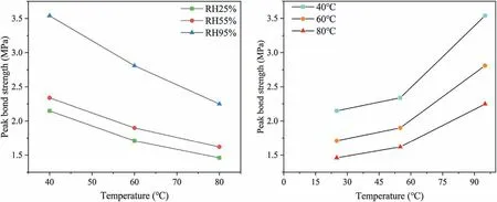
Fig.15.Peak bond strength under different test conditions.
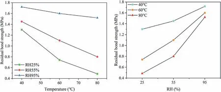
Fig.16.Residual bond strength under different test conditions.
Fig.17 shows that λ increases with a rise in temperature when the curing humidity is at 95%.However, when the RH is kept at a lower level, the curve goes opposite as the temperature rises.Combining the results of failure mechanisms and patterns of test samples,it is found that when the damage occurred at the interface,the increase in temperature significantly reduced the ultimate shear strength of the interface, while temperature and humidity had little effect on residual strength.Therefore,λ increased with a rise in temperature.When failure occurred in the grouting body,the residual strength decreased more significantly than the ultimate strength as the temperature increased.This phenomenon became more prevalent in hot and dry environments.Thus, λ reduced with the rise in temperature.According to the regression analysis of the experimental results,Eq.(2) can be expressed as
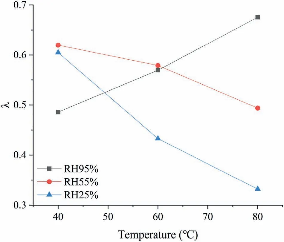
Fig.17.Curves of λ under different test conditions.
3.3.Bond degradation and anchorage interface damage
3.3.1.Damage mechanism of bond anchorage
(1) Hydration properties of grout
Generally, the microstructure of a material determines its macroscopic behavior.A thorough understanding of the relationship between the microstructure and macroscopic properties of cement mortar is crucial for investigating the mechanical properties of anchorage systems.Fig.18 shows the SEM test on samples cured under SC-20°C-95%, VTC-80°C-95%, and VTC-80°C-25%conditions.As the hydration proceeded, the C-S-H gel morphology improved and the CH content increased.Compared with specimens under the SC conditions, the degree of cement hydration for specimens under the VTC conditions was lower at high temperatures.However, this brought about many troubles.Numerous unhydrated cement particles were rapidly encapsulated and microcracks appeared between the cement paste and aggregates when the temperature increased.Excessive heat also caused intensive thermal motion of hydration products, most of which were deposited near the relatively large aggregate, leading to the appearance of weak areas.Additionally,water also played a key role in the whole process of hydration.Compared with VTC-80°C-25%,crystallinity of products under VTC-80°C-95%obviously increased,with a more ordered arrangement and apparent orientation.The grouting material lost water and dried out when the humidity was excessively low, preventing a normal hydration process and resulting in clear perforated structures.With curing age development,the previous unhydrated cement particles produced a larger amount of calcium hydroxide (CH), which had weak inter-layer connections and low strength.On one hand, hydrating products produced by the reaction of water and cement were usually dissolved in the water and moved to the solid granule.On the other hand,the water created an interconnected porous network,where menisci were formed.As the water was consumed, noncompactness and heterogeneity of overall microstructure occurred.CH also caused cracks in the hardened cement mortar under external load.Comparing the aforementioned mechanical tests, it can be found that these microstructural evolution characteristics of the grout had a certain correspondence with the macromechanical response.
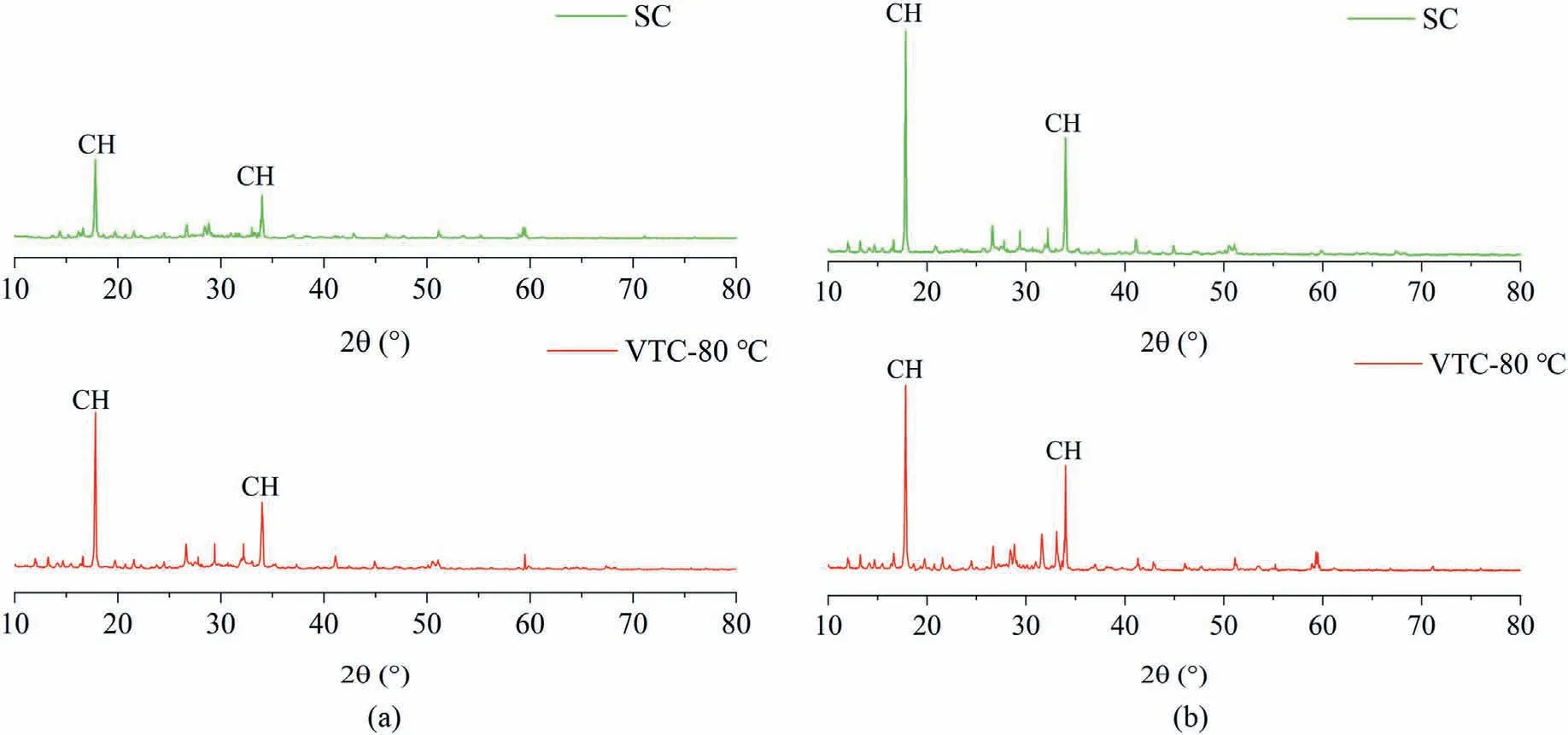
Fig.19.XRD patterns of grout at different curing ages: (a) 3 d, and (b) 28 d.
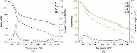
Fig.20.TG and DTG curves of grout under different test conditions: (a) SC, and (b) VTC: 80 °C.
Previous studies have shown that the type and quantity of cement hydration products can indicate the development pattern of cementitious material strength at a microscopic level.The essence of cement hydration is the reaction of water with particulate mineral components such as calcium silicate, calcium aluminate, and iron-phase solid solutions to produce calcium crystals, hydroxide, and calcium silicate hydrate.The cement hydration degree is indirectly influenced by the CH content(Winnefeld et al., 2021).We conducted XRD diffraction tests at a moderate humidity level (RH = 55%) on specimens cured for 3 d and 28 d under standard and high temperature VTC conditions(Fig.19).When the curing age was 3 d,the highest peak value of CH at the 80°C curing condition was at its highest content level.The lowest CH content was generated at the same age under the standard curing condition, and the CH diffraction peak was also low.When the curing age was 28 d, the peak value of CH was lower under the 80°C curing condition than under the standard curing condition, but the amount of hydration products considerably increased in all these specimens after 25 more days of curing.The results show that high-temperature VTC accelerated the cement hydration rate, especially for early cement hydration.Still, one cannot ignore its negative effects on the long-term cement hydration degree.As for the cement hydration reaction,the effect of the high-geothermal environment is insignificant.
Fig.20 and Table 8 show that for cementitious materials used in high-ground-temperature tunnels and with an increase in the TGA test temperature, dehydration decomposition of calcium alumina mainly occurred to produce a monosulfur-type hydrated calcium aluminate and water.After the temperature rose to 400°C, the dehydration and decomposition of CH occurred,generating calcium oxide and water.Generally,the higher the calcium alumina and CH contents, the higher the strength and weight loss percentage after reaching the critical decomposition temperature.TGA results showed that the overall calcium alumina and CH content increased with an increase in the curing age.This phenomenon indicates that the hydration degree and strength both increased.Comparing the TGA test results of the specimens with the curing age of 3 d, the weight loss of calcium alumina at a high temperature was 6.17%,which was less than 8.21%for the SC condition.The decrease in the calcium alumina content relative to the standard condition was mainly due to some decomposition under high temperatures.However, the CH weight loss in the TGA specimens was greater than that in the specimens under the standard condition, i.e.the hydration generation of CH in the TGA specimens was greater than that of the specimens maintained under the standard condition.This phenomenon indicates that the early high-temperature curing accelerated the cementitious material hydration and quickly promoted the overall hydration level, ensuring increased strength.As the age increased, the weight loss percentages of calcium alumina were 3.12% and 1.65% for the two curing conditions (SC and VTC),respectively.The CH weight loss was 2.42% under the standard condition but only 2.04% at the high temperature.This phenomenon indicates that the hydration degree at a high temperature,although elevated, was lower than that at the standard condition.Therefore, the material strength was relatively weak.This result corresponds with the changing pattern of the indoor compressive strength and XRD diffraction peaks of cementitious materials.

Table 8 Weight loss of substance.
(2) Stress transmission at anchorage interface
The anchoring effect of the anchorage system was achieved mainly by load transfer between different strength media for strengthening and limiting the deformation effect on surrounding rocks.Under the pull-out condition, the anchor rod was located in the center of the borehole to support and transfer the pull-out force.The load applied on the anchor rod was transferred to the annular grout body through bonding and friction between the anchor section of the rod and the grout, leading to mechanical occlusion between the anchor rod and grout.Thereafter, the load was transferred to the surrounding geotechnical body by the grout body and surrounding rock body interaction.Fig.21 illustrates the stress pattern.
(i) Chemical bonding force.The chemical cementation force was the shear stress along the longitudinal direction of the anchor, which was produced on the contact surface between the grout and the surrounding medium.The force also determined the stress transfer between different media and ensured local synergistic deformations and joint actions.Insufficient interlaminar bond between the grout and surrounding media caused interlaminar movement, and the bond disappeared when relative displacement occurred.
(ii) Mechanical occlusion force.When the reinforcement surface was fully covered with wrapped grout, the threads on the reinforcement surface, i.e.the equally spaced rib joints,produced relative movement and extrusion with the embedded grout under the pull-out action, forming a mechanical bite.Under a mild pull-out load action, mechanical occlusion and bonding forces often coexisted.
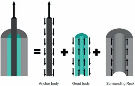
Fig.21.Force pattern of anchorage system under the loading condition.
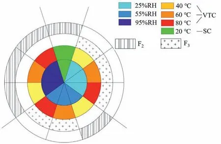
Fig.23.Change of failure pattern at 28 d.
(iii) Friction.The grout body hydration shrinkage produced a grip-wrapping effect on the reinforcement, and the reinforcement ribs extruded towards the inter-rib grout under the pull-out action.The surrounding rock also constrained the grout radial shear expansion deformation.Frictional resistance was generated when a relative slip occurred between the grout and reinforcement interface or surrounding rock with a certain roughness.This friction is crucial in overcoming the chemical bond and mechanical occlusion forces present at the interface.
3.3.2.Relationship between grout properties and anchorage damage
Based on the aforementioned damage mechanism,failure mode,and internal crack evolution characteristics of the anchorage system in high-geothermal environments,we conclude that the failure mode distribution of the anchorage system also has certain regularity under the temperature and humidity coupling effect(Fig.22).From the curing age perspective, the failure mode of specimens under the standard curing condition changed from F1to F3and then to F2as the age increased.However, under high-temperature and low-humidity conditions, the failure mode was always F3regardless of changes in the curing age.Fig.23 illustrates the variation of the anchorage failure mode with temperature and humidity levels for 28 d.At 40°C and 25%humidity,the specimen failure mode was F3.With increasing RH, the specimen failure mode gradually developed to F2.However, at above 60°C, the changing pattern varied.The test statistics show that the failure mode F2occurred only when humidity was 95%,while F3remained as the main failure mode for most specimens.When humidity was 25%, the failure mode was always F3regardless of temperature conditions.
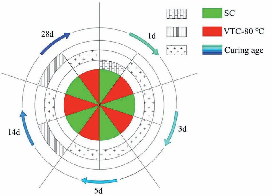
Fig.22.Failure pattern evolution with curing age.
In summary, an association exists among the anchorage performance, failure modes, and strength of grout.Based on the test results, the loss of compressive strength of the grouting material was approximately 7.8%-52.5%,but the drawing force and bonding strength of the rock bolt were 2.9%-69.4% and 3%-60%, respectively.These values indicate that the rock bolt anchorage performance in high-geothermal environments was more susceptible to temperature and RH changes.According to the failure mechanisms,we conclude that the chemical bonding strength was the major resistance of the anchorage system in the failure mode F2.The ultimate drawing force depended mainly on the grouting material shear strength between anchor rod ribs in the F1failure mode.The results demonstrated that the reason for anchor support failure for the F3failure mode was mainly related to the splitting strength of the grouting body.Therefore,the strength of the grouting material greatly affected the anchorage system performance.Fig.24a is an illustration of the results.The failure mode gradually changed from F2to F3with an increase in F′scu.The maximum average tension of the rock bolt was strongly correlated with the compressive strength of the grouting material, and Fpincreased exponentially with a simultaneous increase in F′scu.The relationship between tension force and compressive stress at 28 d was calculated as follows(R2= 0.963):
Similarly, Fig.24b shows that the bonding strength increased with a rise in the compressive strength of the grouting material,and both intensity indices were strongly linearly correlated.Hence,the higher the compressive strength of the grouting material, the higher the ultimate bond strength of the anchorage system.The relationship is expressed as follows (R2= 0.944):
The results presented above demonstrate that the damage mechanism and ultimate strength of the anchorage systems in high-geothermal tunnels depend mainly on the development of mechanical properties of grout under the coupling effect of temperature and humidity.Based on a comprehensive analysis of the anchorage performance, stress transmission at the anchorage interface, and grout properties under high ground temperature environments, the following conclusions are drawn:
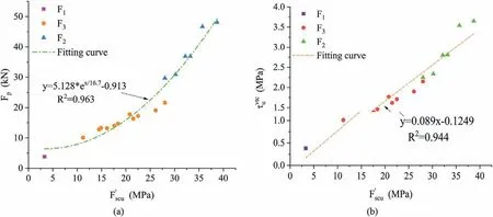
Fig.24.Relationships between Fp, peak bond strength and compressive strength of grouting material: (a) Fp vs.F′scu, and (b) τvtcu vs.F′scu.
(1) Under the pull-out load action, shear stress typically transfers from the anchor body to the first interface,the grout,the second interface, and then finally reaches the surrounding rock.
(2) The first interface has a high shear strength safety reserve because of steel rib joints and threads present on the anchor reinforcement surface.The grouting material injected into the hardened surface forms a strong mechanical bite between the ribs during the pull-out action and chemical bonding.Hence, the shear strength of the first interface is high.In contrast, the second interface only has chemical bonding and friction forces as its main shear force, and the rough surface of the surrounding rock is not as good as the threaded surface of the reinforcement, resulting in a relatively weak shear strength.
(3) The two points above are based on the sufficient hardness of the grout.Environmental parameters complicate the internal stress distribution and strength changes of the grout.The strength of the grout body increases with an increase in curing age and humidity,but high temperature weakens the long-term strength of the grout body significantly.Therefore,due to the stress transfer process and variations in the shear strength of the three regions, the anchorage failure mode changed significantly.
3.3.3.Damage model of interfacial bond stress
The bond interface of the anchorage system was affected by heat in high-geothermal environments.Under external load action,microcracks were more likely to appear and expand at the interface and inside the grouting material.The interface and grouting material damage caused the degradation of bond properties.
The damage degree D was proposed as an index for describing the interface bond damage of the anchorage system due to high geothermal conditions.This index can be expressed by reducing the peak bond strength:
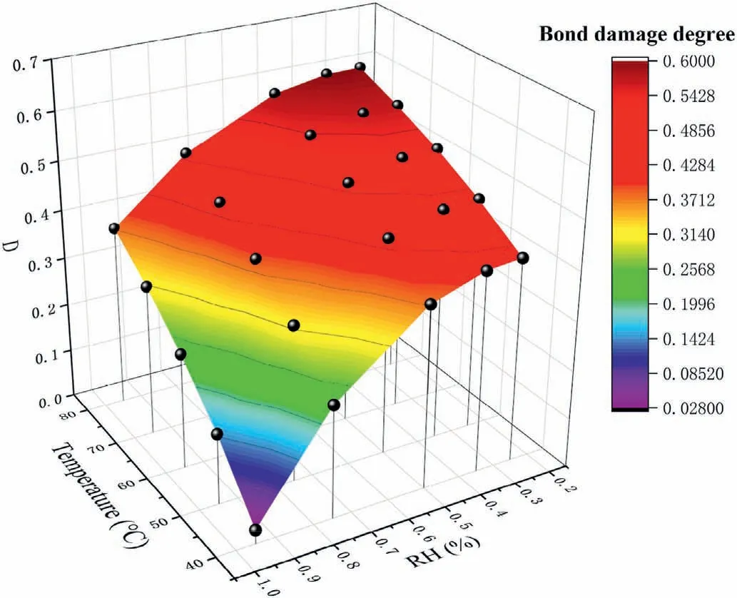
Fig.25.Bond damage degree of grouting material under different curing conditions.
The damage degree model can be obtained using multiple nonlinear regression analyses of temperature and humidity.The model was obtained by interpolated data fitted through the least squares regression analysis as
The damage model for bond strength is obtained as
Introducing Eq.(7) into Eq.(8) gives
Table 9 shows a good agreement between the actual and predicted data.The relative error of interfacial bond stress is less than 5%, indicating that the calculation model sufficiently reflects the coupling effect of temperature and humidity on the bond performance of the anchorage system.
3.3.4.Thermal hazard classification of anchorage system
The established model for calculating the bond stress at the anchorage interface in high-geothermal environments was used to obtain the ultimate bond strength under different temperature conditions,as shown in Table 10.The bond stress at the anchorage interface decreased following an increase in temperature at different humidity levels.In low humidity environments(RH=25%),the attenuation of the anchorage bond strength due to high temperature was from 42% to 60%.In medium-humidity environments(RH=55%),the anchorage shear force attenuation due to high temperature was from 36% to 56%, and in high-humidity environments (RH = 95%), the anchorage shear force attenuation due to high temperature was from 3% to 38%.
The interfacial bond stress functions affected by thermal conditions at different humidity levels were obtained by fitting regressions to the data:
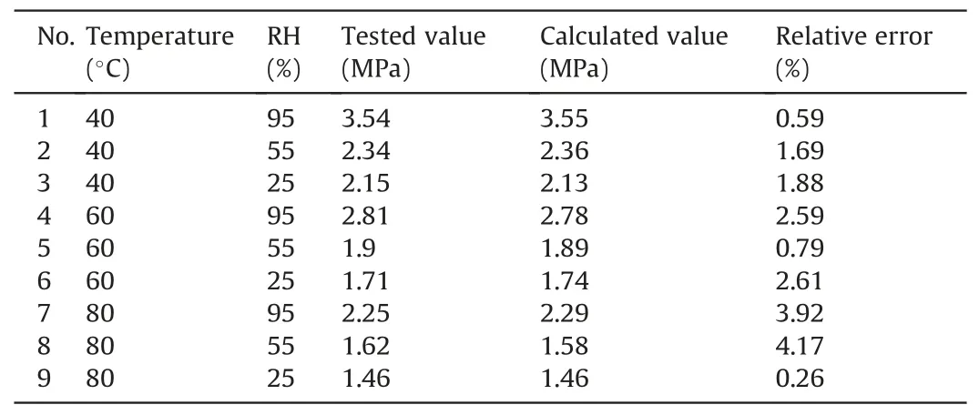
Table 9 Comparison of measured and predicted data.
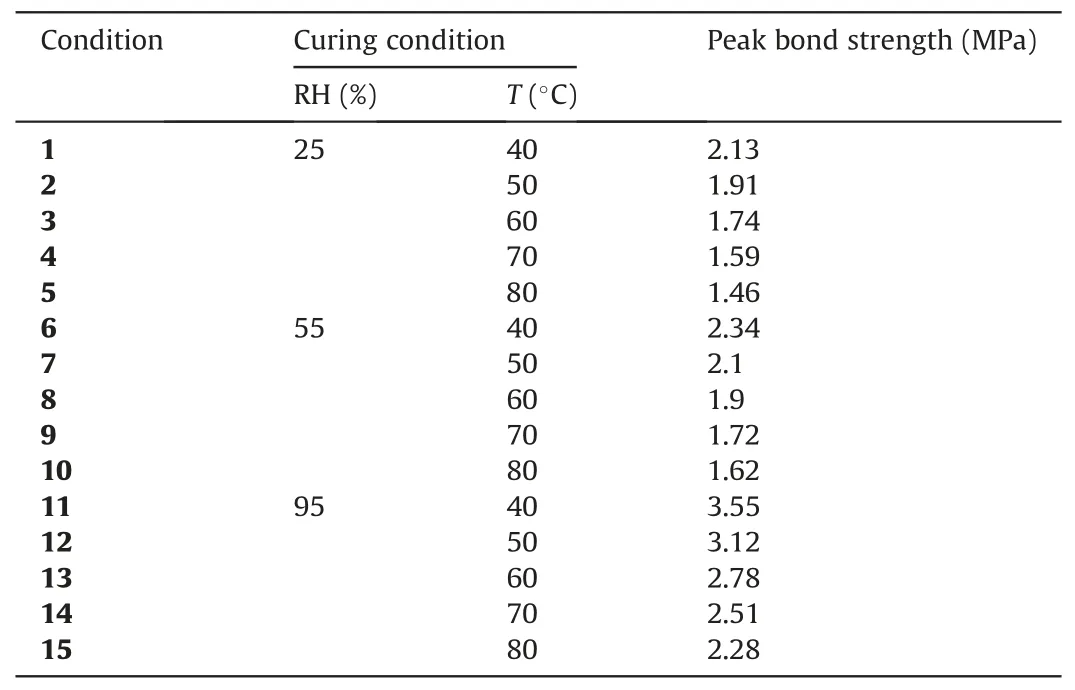
Table 10 Peak bond strength under high geothermal environment.
Taking the residual interfacial strength under the SC condition as the critical strength value of the anchorage system, the critical temperature Tlimresulting in the deterioration of anchorage performance at different humidity levels is represented in Eq.(13),which was developed using the calculations of Eqs.10-12.
Fig.26 shows that a reduction in RH resulted in a significant decrease in critical temperature.When the temperature of surrounding rocks exceeded the critical value, the bearing capacity of the anchorage system reached its limit,characterizing the damage caused by the coupling effect of temperature and humidity on the anchorage system.The critical temperature required to strengthen the anchorage design in high-geothermal tunnels was obtained through inductive analyses(Table 11).The high temperature had a stronger influence on anchorage properties at levels I and II of heat damage.The conclusion may provide references for the design of high-geothermal tunnel support.However, the results obtained in this study also had some limitations.The findings in this paper were obtained from tests with a temperature range of 40°C-80°C and thereby should be further examined when applied to highgeothermal tunnels in areas with abundant geothermal resources,where the ground temperature reaches up to 98°C.Moreover,although this work presents plenty of fundamental research on the damage mechanism of anchorages in high-geothermal tunnels, no consideration was given to reduce the adverse effects of highgeothermal environments on the anchoring system by special support materials and structural forms, and the theoretical calculation model has a room for improvement by more field validations.Besides the above, considering that current design of rock bolts is usually implemented in parallel with the design of shotcrete support, accounting for the comprehensive effect of high-geothermal environment on the anchor spray composite support structure and providing the corresponding design method is of great importance for engineers to build such kind of tunnels safely.
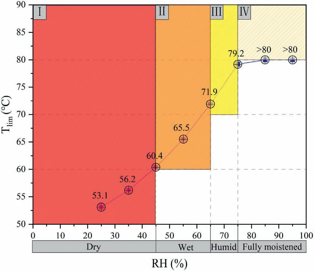
Fig.26.Critical temperature variation with humidity in high-geothermal tunnels.

Table 11 Classification of anchorage design in high geothermal tunnels.
4.Conclusions
The unique environment of high-geothermal tunnels significantly influences grouting material properties, resulting in the degradation of the strength of the anchorage system.In this study,theoretical and experimental investigations were performed on the anchoring performance and strength of grouting materials.Some major conclusions can be drawn as follows:
(1) Compared to SC conditions,high initial curing temperatures of the VTC condition promoted the compressive strength of the grouting material by 16%-36%at the early age(5 d),but sacrificed the late-stage strength up to 30% because of the crossover effect caused by excessive heat in the highgeothermal environment.Moreover, during the hardening process of the grouting material cured under a high temperature, high moisture attenuates the loss of macroscale strength, evidenced by the reduction in the grout compressive strength loss from 25%at 80°C to 20%at 40°C due to the increase of humidity.
(2) Three typical failure patterns were observed in the bolt pulling tests under a high-geothermal environment: failure of the bonding interface between the rock bolt and grouting body (F1), damage of the interface between the grouting body and rock mass (F2), and damage of the grouting material(F3).The differences in the generation and development of cracks indicated that the curing temperature and RH indirectly influenced the failure patterns and ultimate anchorage force of the anchoring system by modifying the grouting body properties.
(3) High curing temperatures accelerated the development of the ultimate drawing force of the rock bolt at early ages but also caused deterioration to long-term anchorage performance.The ultimate drawing force decreased by 2.7%-38.1%at 28 d compared with the samples cured under the SC condition, and the loss rate was even more than 60% in hot and dry environments.The higher the curing temperature,the greater the reduction of the bonding strength.However,the higher the RH,the less the loss of the bonding tension at high temperatures.
(4) For a curing age of 28 d,the peak value of calcium hydroxide for specimens under 80°C was smaller than that of the specimens under the standard condition, but a significant increase in the amount of hydration products occurred for specimens under both conditions after the third day of curing.The weight loss percentage of calcareous alumina under high temperature and standard conditions increased by 3.12%and 1.65%,respectively.However,the weight loss of calcium hydroxide was 2.42% under standard condition and only 2.04% under high temperatures.The high-geothermal environment essentially affected the degree of the hydration reaction of the grouting material, weakening the material microstructure and contact properties with the surrounding medium.Therefore, the decay of mechanical properties of grout at the composite interface of the anchorage structure due to microscopic changes was the main reason for the degradation of the support performance of the anchorage system.
(5) A comparison of the experimental data and theoretical calculation results showed that the damage model of the anchored structure established in this study accurately characterized the bond strength degradation of the anchored interface under a high-geothermal environment,with errors less than 5%.Based on the anchorage residual strength, a thermal damage classification of the anchorage design was proposed by considering the coupling effect of temperature and humidity.With the increase of ambient humidity, the limit critical temperature of the anchorage design increased from 50°C to 80°C.
Declaration of competing interest
The authors declare that they have no known competing financial interests or personal relationships that could have appeared to influence the work reported in this paper.
Acknowledgments
All the authors would like to acknowledge financial support from the National Natural Science Foundation of China (Grant No.52208387) and Open Fund of Key Laboratory of Geohazard Prevention of Hilly Mountains, Ministry of Land and Resources, China(Fujian Key Laboratory of Geohazard Prevention) (Grant No.FJKLGH2022K001).
 Journal of Rock Mechanics and Geotechnical Engineering2023年10期
- Journal of Rock Mechanics and Geotechnical Engineering的其它文章
- Analytical solutions for the restraint effect of isolation piles against tunneling-induced vertical ground displacements
- Characterizing large-scale weak interlayer shear zones using conditional random field theory
- Displacement-based back analysis of mitigating the effects of displacement loss in underground engineering
- Investigation of long-wavelength elastic wave propagation through wet bentonite-filled rock joints
- Mechanical properties of a clay soil reinforced with rice husk under drained and undrained conditions
- Evaluation of soil fabric using elastic waves during load-unload
