Investigation of long-wavelength elastic wave propagation through wet bentonite-filled rock joints
Ji-Won Kim, Song-Hun Chong, Jin-Seop Kim, Geon-Young Kim
a Disposal Performance Demonstration R&D Division, Korea Atomic Energy Research Institute, Daejeon, 34057, Republic of Korea
b Department of Civil Engineering, Sunchon National University, Suncheon, 57922, Republic of Korea
Keywords:
ABSTRACT The saturation of the compacted bentonite buffer in the deep geological repository can cause bentonite swelling, intrusion into rock fractures, and erosion.Inevitably, erosion and subsequent bentonite mass loss due to groundwater inflow can aggravate the overall integrity of the engineered barrier system.Therefore, the coupled hydro-mechanical interaction between the buffer and rock during groundwater inflow and bentonite intrusion should be evaluated to guarantee the long-term safety of deep geological disposal.This study investigated the effect of bentonite erosion and intrusion on the elastic wave propagation characteristics in jointed rocks using a quasi-static resonant column test.Jointed rock specimens with different joint conditions (i.e.joint surface saturation and bentonite filling) were prepared using granite rock discs sampled from the Korea Underground Research Tunnel (KURT) and Gyeongju bentonite.The long-wavelength longitudinal and shear wave velocities were measured under different normal stress levels.A Hertzian-type power model was used to fit the wave velocities, and the relationship between the two fitted parameters provided the trend of joint conditions.Numerical simulations using three-dimensional distinct element code (3DEC) were conducted to better understand how the long-wavelength wave propagates through wet bentonite-filled rock joints.
1.Introduction
Deep geological disposal is the preferred method for high-level nuclear waste(HLW)disposal(Chapman,2006;Wang et al.,2018).The Korean Reference HLW Disposal System is a multi-barrier repository concept comprising an engineered barrier system (EBS)and a natural rock barrier.An EBS consists of a deposition tunnel,deposition hole, copper disposal canister, compacted bentonite buffer, and backfill material (Fig.1).The compacted bentonite buffer installed in the deposition hole is a major component of the EBS that provides physical protection to the disposal canister,prevents groundwater intrusion,and disperses the heat generated from the HLW (Lee et al., 2016).Construction of the repository inevitably causes excavation damaged zone (EDZ) within the host rock.The rock fractures within the EDZ and pre-existing rock joints create unfavourable pathways for groundwater inflow into the repository, resulting in eventual saturation of the compacted bentonite buffer during operation and after closure of the repository (Kwon et al., 2009).
Saturated bentonite displays high swelling characteristics, and the highly hydrated bentonite platelets eventually become disassociated with swelling.The resulting swelling pressure can lead to penetration of the bentonite into the rock discontinuities surrounding the deposition hole (Neretnieks et al., 2009; Hedström et al., 2016).This process, hereafter called intrusion, can lead to the loss of bentonite mass and nuclide migration owing to increased permeability, affecting the physical integrity of the EBS(Baik et al.,2007).Multiple bentonite phases such as paste,gel,and sol can exist within the rock joint depending on the distance from the deposition hole, as shown in Fig.1.Bentonite-infiltrated rock joints display different mechanical behaviours depending on the bentonite phase.Therefore, it is necessary to investigate how the interaction and complex behaviour between the bentonite buffer and rock joint affect the mechanical properties of the EDZ.

Fig.1.Schematic diagram of the Korean Reference High-Level Nuclear Waste Disposal system concept and the rheological states of bentonite penetrating into a rock fracture(Modified from Birgersson et al., 2009).
Seismic wave exploration techniques have been widely used to characterize jointed rocks from infrastructure (e.g.rock slope and tunnel) to resource recovery and production (e.g.geothermal development and oil production).Geophysical methods have also been employed to monitor radioactive waste repositories (Marelli et al., 2010; Manukyan et al., 2012; Biryukov et al., 2016).However, the relation between wavelength and internal spatial scale (i.e.joint spacing) is necessary for interpretation of the seismic wave data in a rock-joint system.Yang et al.(2020,2021)investigated the effects of joint water saturation and bentonite infill saturation on the short-wavelength propagation characteristics of single rock joint using ultrasonic transducers.However, the measurements of high frequency response are limited to laboratory-scale wave propagation.In situ rock mass acts as a low-pass filter, and the group velocity decreases as the wavelength approaches the internal length scale and the wave velocity shows frequency-dependency with cutoff wavelength.Thus, it is desirable to propagate the long-wavelength through the entire rock-joint system as an equivalent continuum with an equivalent modulus (Schoenberg and Muir,1989; Sitharam et al., 2001; Li et al., 2010).The equivalent modulus can be used to represent the mechanical characteristics of the EDZ.
Fratta and Santamarina (2002) invented the quasi-static resonant column (QSRC) test to produce long-wavelength shear wave propagation in jointed rocks and explored the effects of joint fill thickness of clay joint fill.Previous experimental and numerical studies used the QSRC test to investigate the effects of joint roughness, joint spacing, joint fill material, joint fill thickness, and joint cementation on the wave propagation characteristics of jointed rocks (Cha et al., 2009; Mohd-Nordin et al., 2014; Chong et al., 2020, 2021; Kim et al., 2021).
In this study,experimental tests were conducted to examine the effects of bentonite intrusion on the coupled mechanical behaviours of buffer-rock interactions using the QSRC test.The bentonite intrusion was replicated by adding various mixtures of Gyeongju bentonite and water.Changes in the mechanical properties of the rocks with bentonite intrusion were inferred from the longwavelength longitudinal and shear wave velocities under different normal stress and intrusion conditions.Numerical study was conducted to understand how the long-wavelength wave propagates through the wet bentonite-filled rock joints.
2.Material and methods
2.1.Sample preparation
Granite sampled from the Korea underground research tunnel(KURT) facility at the Korea Atomic Energy Research Institute was used to replicate the in situ host rock.At the centre of the 51.5 mm diameter granite core,17 mm diameter holes were drilled using a high-pressure waterjet.Afterwards,the granite core was cut using a diamond saw to create ten hollow cylindrical rock discs of 27.5 mm thickness.A total of 10 discs were vertically stacked to simulate a jointed rock mass with regularly spaced joints.An internal plastic membrane consisting of a rolled soft plastic folder was added to the inner hole of the specimen and external rubber membranes were attached to each joint location.Indeed,the rubber membranes can prevent any mass loss of the joint fill material during testing.The rock discs were washed and oven-dried for 48 h at 105°C before and after each test for consistency.
The wet joint surfaces were prepared by injecting 10 mL of water into each joint location using a syringe.Bentonite intrusion was reproduced by injecting bentonite gel or adding bentonite paste to rock joints.Tap water of 400 mL was added to 300 g of Gyeongju bentonite and stirred thoroughly.The mixture was allowed to settle for 24 h.The stable gel formation at the top of the mixture was collected using a syringe and injected at each joint location.In addition, the bentonite paste was collected from the surface of the mixture, and 2 g of that paste with an initial water content of 40% was smeared onto the surface of each rock joint during the specimen preparation process.Different vertical loading levels were applied using a thin rod placed along the centre of the discs.The properties of the jointed rock specimens and joint fill materials are summarized in Tables 1 and 2.
2.2.Experimental setup
Fig.2 shows the QSRC testing setup to measure long-wavelength longitudinal and shear elastic wave propagation in the jointed rock specimens.The setup consists of a top cap, loading rod,steel base,and lever loading system.The jointed rock specimens were placed on the steel base, and the top cap was installed on top of the specimen to simulate fixed/free boundary conditions.The top capand the steel base were connected using a loading rod placed within the internal hole of the specimen.The loading rod was connected to the lever loading system to apply axial stress to the entire specimen.The longitudinal wave was generated by dropping the steel ball onto the surface of the disc at the top of the rock column.Fig.3a presents the selected time-domain longitudinal wave velocity computed using the time difference between the top and bottom accelerometer signals.A brittle mechanical pencil lead was used to excite torsional mode at the top cap and the corresponding shear wave velocity was obtained from the resonant frequency of the fixed/free specimen under torsional excitation.The time-domain signals of the two accelerometers attached to top cap were added and transformed to the frequency-domain via fast Fourier transformation, as shown in Fig.3b and c.While the damping and attenuation in rock joints are an important indicator in understanding the energy dissipation mechanism, this study focuses on the wave velocity trends under different joint conditions.Further experimental studies will quantify the energy dissipation associated with the jointed rock mass system during longwavelength propagation.

Table 1 Material properties of jointed rock specimens.

Table 2 Material properties of Gyeongju bentonite (KJ-II).
3.Results and discussion
3.1.Effects of joint surface wetting and bentonite penetration
Fig.4 shows the changes in the longitudinal and shear wave velocities of the jointed rock specimens with joint surface wetting and bentonite intrusion.The dry joint surface specimen displays a longitudinal wave velocity of 1752-3346 m/s.The wet joint surface specimen shows an average increase of 14.2% in the longitudinal wave velocity with joint surface wetting.The bentonite gel and paste fill display respectively an average 47.8%and 66.7%increase in longitudinal wave velocity compared to the dry joint surface condition.The longitudinal wave velocity increases with increasing normal stress for all tested jointed rock specimens due to improved contact area and joint stiffness between contiguous rock discs.The gradual increase in wave velocity with different bentonite concentrations,or“mass fraction”,in the joint fill material implies that the bentonite mass fraction within the joint filling material significantly influences the wave propagation characteristics of the jointed rock.The bulk modulus of bentonite decreases progressively with increasing water saturation and swelling (Zheng and Zaoui, 2018).Bentonite has a greater bulk modulus compared to water.Considering the two extreme cases of a dry bentonite powder joint fill and water joint fill, a greater bentonite mass fraction will result in a larger bulk modulus of the joint fill material.In this respect, the general order of the wave velocity magnitude follows the order of the bulk modulus of the joint fill material.
Compared to longitudinal waves, the effects of joint surface wetting and bentonite intrusion are less pronounced for shear waves.The wet joint surface specimen displays an average 8%initial decrease in shear wave velocity(568-1687 m/s)with joint surface wetting.The bentonite gel and paste-fill rock joints present respectively an average 6.1% and 23.5% increase in longitudinal wave velocity respectively compared to the dry joint surface condition.The initial decrease in the shear wave velocity with joint surface wetting can be attributed to the lubrication effects of the joint fill fluid.Previous studies show that the presence of water within the rock joint surface can act as a lubricant, eventually reducing the shear stiffness and friction angle of the joint interface(Horn and Deere,1962;Morrow et al.,2000).Laboratory-scale tests on rock joints using direct shear tests, triaxial tests, and tilt tests also confirm a decrease in the shear strength and friction angle with joint surface wetting and saturation(e.g.Jaeger,1959;Hoskins et al.,1968;Gutierrez et al.,2000;Li et al.,2005;Pellet et al.,2013;Ulusay and Karakul, 2016).
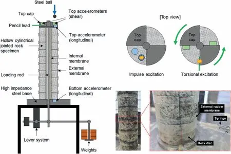
Fig.2.Quasi-static resonant column test (QSRC) setup used in this study.

Fig.3.Data analysis of QSRC results on dry joint surface rock specimens at 1.06 MPa normal stress.(a) Time-domain signal of longitudinal wave propagation; (b) Time-domain signal of shear wave propagation; and (c) Frequency response in torsional mode.The time-domain signals in torsional mode were obtained from two accelerometers located on the diametrically opposite directions.The two accelerometer signals were added to enhance the torsional mode.
The bentonite paste has a comparatively lower water content than the bentonite gel.Hence, the friction losses within the bentonite paste caused by the relative fluid-solid and solid-solid motions are expected to be relatively high, resulting in higher attenuation(Lucet and Zinszner,1992).However,the bentonite gel fill specimen displays the largest attenuation characteristics at low normal stress levels below 2 MPa,while the damping ratios of the wet joint surface and bentonite paste-filled specimens are similar.Yang et al.(2021)noted a similar trend,where the wave attenuation of single bentonite-filled rock joints first decreased and then increased with increasing water saturation.This phenomenon was attributed to the enhanced local flow within the bentonite joint fill and improved wave reflections at the clay-rock interface due to the decreased shear modulus of bentonite (Zhu et al., 2011).With increasing degree of saturation, the friction losses due to the relative fluid-solid and solid-solid motions in the joint fill clay diminish and less wave attenuation occurs.On the other hand, increasing degree of saturation also significantly reduces the shear modulus of the joint fill clay,resulting in more wave reflections at the clay-rock.A critical water content value is expected to be determined where the increased attenuation due to local flow and wave reflections is larger than the decreased attenuation due to viscous loss of the joint fill material.It can be inferred that the water content of the bentonite gel fill in this study is above the critical value such that the attenuation is larger than that of bentonite paste fill.Extensive testing using different gel concentrations and additional assessment of the rheological properties of Gyeongju bentonite are required for a more comprehensive assessment.
3.2.Velocity-stress relationships
Jointed rocks are analogous to particulate media because the stiffness of the rock mass is significantly influenced by the joint stiffness.The following Hertzian power functions can be used to fit the long-wavelength longitudinal wave velocitynd longwavelength shear wave velocitywith normal stress(Hardin and Richart,1963):

Fig.4.Effects of joint surface wetting and bentonite intrusion on long-wavelength wave propagation characteristics.(a) Longitudinal wave velocity; and (b) Shear wave velocity.The legends describe the joint fill conditions.The trend lines are fitted with Eqs.(1) and (2) to quantitatively evaluate the effect of bentonite-filled rock joints.When the normal stress equals the reference stress(σ′n=σ′ref),the α factors(αP and αS)correspond to the longitudinal and shear wave velocities,respectively.The β exponents(βP and βS)denote the stress sensitivity of the jointed rock mass for long-wavelength longitudinal and shear wave propagation, respectively.

Fig.5.The rock-mass wave parameters fitted with Herzian-type power function for various bentonite infiltration conditions.The arrow highlights trends for selected variables of jointed rocks.
3.3.Effects of bentonite intrusion on mechanical properties of rock joints
The changes in the mechanical behaviour of the rock joint with saturation and bentonite intrusion can be quantified via the joint normal stiffness knand joint shear stiffness ksusing the equivalent continuum jointed rock mass model.Joint stiffness is an essential parameter of joints or fractures, which governs the mechanical behaviour of a rock mass, and wave-based geophysical techniques are often adopted to locate and assess the dynamic stiffness characteristics of rock fractures (Cook, 1992).It is noted that the dynamic joint stiffness calculated from the wave velocity differs from the traditional definition of rock joint stiffness.However, the changes in the dynamic joint normal and joint shear stiffness trends with joint fill condition can provide insight into the mechanical behaviour of rock joints during bentonite infiltration.
Considering a rock mass with regularly spaced joints of joint spacing S,the equivalent Young′s modulus Eeqand equivalent shear modulus Geqcan be calculated using the following equations(Goodman,1989):
where E0and G0are the Young′s and shear moduli of the intact rock, respectively.Similar to the wave velocity, the changes in dynamic joint normal stiffness kndyn and dynamic joint shear stiffness ksdyn with normal stress σ′ncan be quantified using a similar Hertzian power function as follows:
The stress-dependent joint stiffness and wave velocity can be used to obtain the equivalent moduli of the jointed rocks.Generally,the shear wave velocity VSof a medium is related to its shear modulus G and its density ρ as follows:
By substituting Eqs.(6)and(7)into Eq.(4),the equivalent shear modulus of the jointed rock mass can be calculated from the wave velocity data obtained from the QSRC tests as follows:

Fig.7.3D jointed rock specimen.The joint locations are highlighted in yellow.
A similar argument can be made for the longitudinal wave velocity and equivalent Young′s modulus.The dynamic joint normal stiffness and dynamic joint shear stiffness are plotted with the values of corresponding α factors and β exponents in Fig.6.The magnitude of the joint normal stiffness increases in the following order: dry joint surface, wet joint surface, bentonite gel fill, and bentonite paste fill.For joint shear stiffness, the wet joint surface and bentonite gel-filled joint display lower joint stiffness than the dry joint surface specimen.Considering HLW disposal,higher joint normal stiffness and joint shear stiffness are expected near the deposition hole, where the intruded bentonite exists in a paste form,and the joint stiffness is expected to decrease gradually with increasing distance from the deposition hole.However, the high confinement provided by the host rock at greater distances away from the deposition hole is expected to minimize the effects of bentonite intrusion on the behaviours of rock joints.Nevertheless,the joint stiffness trends with bentonite infiltration observed in this study are relevant to rock joints in the vicinity of the deposition hole.The exact changes in the joint normal and joint shear stiffness due to bentonite intrusion must be assessed via traditional direct shear or triaxial tests on jointed rock samples.
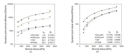
Fig.6.Evolution of equivalent dynamic joint stiffness for different normal stress levels.The lines superimposed on data points show the fitted equation: (a) Dynamic normal stiffness; and (b) Dynamic shear stiffness.The corresponding joint parameters are tabulated in the figure.
4.Numerical modelling
4.1.Modelling procedure
Complementary numerical simulations were conducted using the three-dimensional(3D)distinct element code(3DEC)to better understand how long-wavelength elastic waves propagate through bentonite-filled rock joints.The 3D model of the jointed rock specimen is shown in Fig.7.The model consists of 10 stacked rock discs of 51.5 mm diameter and 27.5 mm thickness to simulate the jointed rock specimens used in the QSRC tests.A linear elastic material model and an elastic joint model were assigned to the rock discs and rock joints respectively as the QSRC test only considered deformations within the elastic domain.The maximum element size and time increment were optimized in explicit time-marching scheme to guarantee numerical stability.For example, extremely large grid dimensions filter high frequencies, whereas extremely small grid dimensions cause numerical instabilities and require considerable computational cost (Villiappan and Murti, 1984;Saenger et al., 2000).In this study, the mesh grid size was set as 0.005 m and the time increment was calculated as Δt = 0.1 μs,satisfying the spatial and temporal Nyquist limits simultaneously(see Chong et al., 2021).
A reference 1.06 MPa stress was applied to the top of the specimen.For longitudinal wave propagation, non-reflective viscous boundaries were assigned to the joints in the joint plane direction to prevent wave reflections at the joint interface.The bottom boundary was fixed for shear wave propagation to simulated fixedfree boundary conditions.Longitudinal impact was applied at the top of the specimen using a half sine function of 0.14 ms period and a maximum force of 1.6 N to simulate the impact from the steel ball.Torsional shear excitation was applied at two diametrically opposite locations on the top of the specimen in the opposite direction to simulate free torsional vibrations.The torsional shear excitation is a linearly increasing half triangle function with a maximum force of 3.7 N,which was removed instantly at 0.1 ms.Both the longitudinal wave and shear wave excitation inputs were applied as transient load boundaries to their respective positions.The input material and joint parameters are listed in Tables 3 and 4.

Table 3 Material properties used in numerical analysis.

Table 4 Joint properties used in numerical analysis.
4.2.Numerical results
Fig.8 shows the time domain signals and frequency responses obtained from numerical analysis of the KURT granite specimen for different joint fill conditions at normal stress of 1.06 MPa.The longitudinal wave signals are normalized by the maximum amplitude of the received wave signal dry joint specimen.As expected,the longitudinal wave signals show faster arrival time with joint wetting and bentonite intrusion as shown in Fig.8a.Fig.8b displays the frequency-domain torsional shear wave signals.A clear peak resonant frequency is observed for all simulated joint fill conditions.The jointed rock specimen shows a decrease in peak frequency and an increase in autospectral density with joint wetting.The peak frequency increases with higher bentonite contents,implying changes in the torsional vibration modes of the specimen for different joint fill conditions.
Figs.9 and 10 present the longitudinal and shear wave velocity cascades in each rock disc for different joint fill conditions.For the longitudinal wave velocity, the colour-scale and the time-domain signals at the top and bottom discs show the wave energy transmission between the joint interfaces.The wave velocity propagating through the different joint surfaces displays a clear wave front (peaks and troughs) throughout the length of the specimen.The amplitude of the received signal at the bottom disc decreases with increased joint stiffness.For the shear wave velocity cascades,a clear shift in resonant frequency and a decrease in autospectral density are observed in the frequency-domain cascade.The peak frequency increases and the autospectral density decreases with increasing joint stiffness.
The longitudinal and shear wave velocities for different joint fill conditions obtained from the numerical simulation are compared with the experimental results (see Fig.11).The numerical analysis results show a good agreement with the experimental results.The average difference of 6% attributes to the idealized modelling of inherently heterogeneous rock joints and the characteristics of bentonite gel and paste.It is difficult to achieve perfectly smooth rock surfaces as minute asperities and imperfect joint contact conditions are formed during the manufacture process.Such joint conditions can affect the longitudinal wave velocity in the discstacked column specimen as the contact area between adjacent rock joint surfaces significantly influences the wave propagation characteristics in the jointed rock mass system.Additionally, the bentonite content-dependent viscosity within the rock joints affects the joint contact conditions and subsequent wave propagation characteristics.
4.3.Implications for HLW disposal
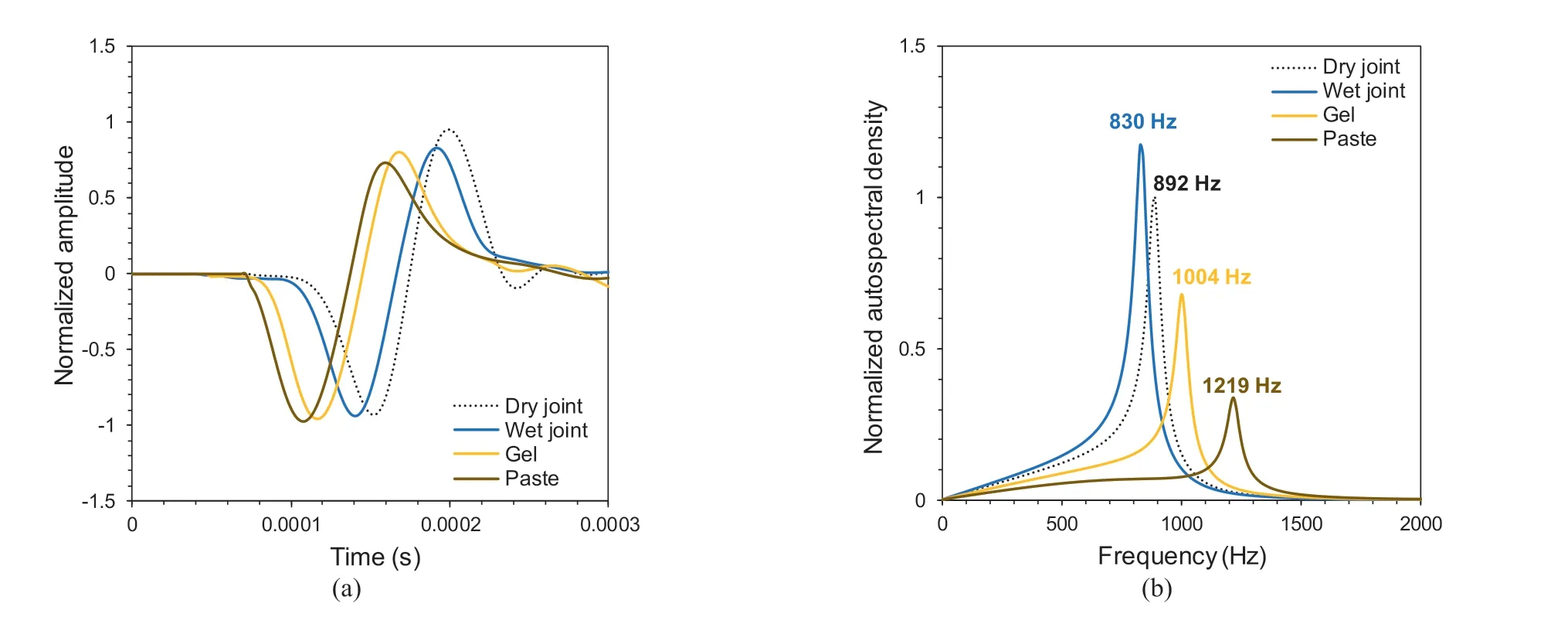
Fig.8.Wave signals and frequency responses obtained from numerical analysis of the KURT granite specimen for different joint fill conditions at the reference normal stress of 1.06 MPa: (a) Time-domain longitudinal wave signals; and (b) Frequency response obtained from the added time-domain shear wave signal.
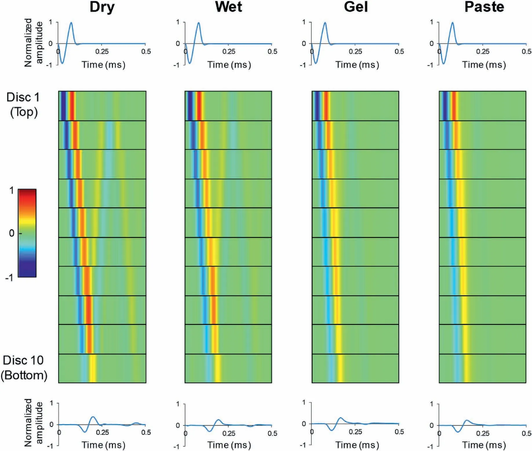
Fig.9.Longitudinal wave velocity cascade in each rock disc for different joint fill conditions.The colour scale represents the signal amplitude in each rock disc on a scale from-1 to 1,where red represents the peaks and blue represents the troughs.The time-domain data of the top and bottom discs are shown for reference.The amplitude of the time-domain data is normalized by the maximum amplitude of the wave signal in Disc 1 for each joint fill condition.

Fig.10.Shear wave velocity cascade in each rock disc for different joint fill conditions: (a) Time domain; (b) Frequency domain.
Considering HLW disposal,the proposed dynamic joint stiffness can be used to obtain the equivalent Young′s modulus and equivalent shear modulus of the EDZ for different bentonite joint fill conditions.In general, the EDZ is modelled using identical properties to the host rock.However, the presence of rock discontinuities in the EDZ will negatively affect its mechanical properties.By modelling the EDZ of the deposition tunnel and deposition hole using the equivalent moduli of jointed rocks, a more accurate assessment of long-term structural safety and stability of deep geological HLW disposal repositories can be considered.In addition,the mechanical degradation associated with bentonite erosion and intrusion can also be applied to the overall EDZ.Further tests considering different bentonite mass fractions in the joint fill material can help quantify the effects of bentonite intrusion on the overall mechanical characteristics of the EDZ.From a wave propagation prospective,the rock heterogeneity,in situ stress levels and complex rock joint systems with different joint scales need to be further considered in the numerical model (Fan and Sun, 2015; Ba et al., 2017; Fan et al.,2018; Fan et al., 2021).
5.Conclusions
In this study, experimental and numerical studies were performed to investigate the effects of bentonite infiltration on the long-wavelength elastic wave propagation characteristics of jointed rock masses.
(1) Joint surface wetting resulted in an average 14.2%increase in longitudinal wave velocity due to the coupling and stiffening effects of the joint fill fluid.Joint surface wetting also resulted in an average 8% decrease in shear wave velocity owing to fluid-induced lubrication and joint sliding.The effects of the joint fluid conditions were minimal at normal stress levels above 2 MPa.
(2) The longitudinal wave velocity was increased by an average 47.8% and 66.7% with bentonite gel and bentonite paste intrusion, respectively.The shear wave velocity was increased by an average 6.1% and 23.5% with bentonite gel and bentonite paste intrusion, respectively.
(3) The general velocity-stress relationship displayed a gradual increase in wave velocity and a decrease in stress sensitivity with joint saturation and bentonite intrusion.The shear wave velocity exhibited an initial decrease in wave velocity and an increase in stress sensitivity with joint surface wetting and lubrication.
(4) Numerical simulations using the dynamic joint stiffness values inferred from the wave velocity data showed a good agreement with the experimental results within 6% error.The velocity cascades were capable of replicating the changes in the long-wavelength wave propagation characteristics of jointed rock masses for different bentonite intrusion conditions.
(5) The equivalent moduli obtained from the experimental tests could be used as numerical input parameters for the longterm stability analysis of deep geological repositories for HLW disposal considering bentonite erosion and intrusion.
While Gyeongju bentonite and KURT granite were used in this study, the exact location of the deep geological disposal site in Korea and the type of bentonite used for the compacted bentonite buffer have yet to be determined.Generally, bentonites can be divided into sodium-type and calcium-type bentonites depending on the type of exchangeable cations, and these two types of bentonite display drastically different erosion characteristics.The erosion characteristics of bentonite are also dependent on the chemical composition of the groundwater, such as ion strength,salinity, and pH value.Further tests considering site-specific conditions should be conducted for a more accurate assessment of bentonite erosion.
Declaration of competing interest
The authors declare that they have no known competing financial interests or personal relationships that could have appeared to influence the work reported in this paper.
Acknowledgments
We acknowledge the funding support from the Nuclear Research and Development Program of the National Research Foundation of Korea (Grant Nos.2021M2E1A1085193 and 2020M2C9A1062949).
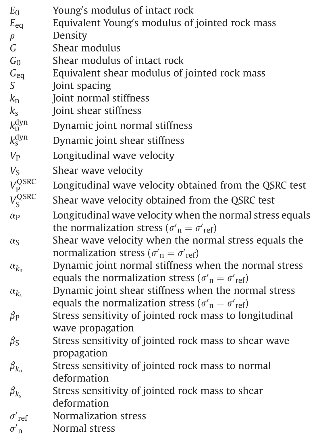
List of symbols
 Journal of Rock Mechanics and Geotechnical Engineering2023年10期
- Journal of Rock Mechanics and Geotechnical Engineering的其它文章
- Analytical solutions for the restraint effect of isolation piles against tunneling-induced vertical ground displacements
- Characterizing large-scale weak interlayer shear zones using conditional random field theory
- Displacement-based back analysis of mitigating the effects of displacement loss in underground engineering
- Mechanical properties of a clay soil reinforced with rice husk under drained and undrained conditions
- Evaluation of soil fabric using elastic waves during load-unload
- Effects of non-liquefiable crust layer and superstructure mass on the response of 2 × 2 pile groups to liquefaction-induced lateral spreading
