Analytical solutions for the restraint effect of isolation piles against tunneling-induced vertical ground displacements
Liqing Co, Xingsheng Chen, Xing-To Lin,*, Dong Su, Hungcheng Fng,Dechun Lu
a Institute of Geotechnical and Underground Engineering, Beijing University of Technology, Beijing,100124, China
b Underground Polis Academy, Shenzhen University, Shenzhen, 518060, China
c College of Civil and Transportation Engineering, Shenzhen University, Shenzhen, 518060, China
d Department of Civil and Environmental Engineering, The Hong Kong Polytechnic University, Hung Hom, Kowloon, Hong Kong, China
Keywords:
ABSTRACT This paper presents a simplified elastic continuum method for calculating the restraint effect of isolation piles on tunneling-induced vertical ground displacement, which can consider not only the relative sliding of the pile-soil interface but also the pile row-soil interaction.The proposed method is verified by comparisons with existing theoretical methods, including the boundary element method and the elastic foundation method.The results reveal the restraining mechanism of the isolation piles on vertical ground displacements due to tunneling, i.e.the positive and negative restraint effects exerted by the isolation piles jointly drive the ground vertical displacement along the depth direction from the original tunneling-induced nonlinear variation situation to a relatively uniform situation.The results also indicate that the stiffness of the pile-soil interface, including the pile shaft-surrounding soil interface and pile tip-supporting soil interface,describes the strength of the pile-soil interaction.The pile rows can confine the vertical ground displacement caused by the tunnel excavation to the inner side of the isolation piles and effectively prevent the vertical ground displacement from expanding further toward the outer side of the isolation piles.
1.Introduction
In recent years, the development of urban underground rail transit has made an important contribution to alleviating surface traffic and boosting the economy (Cao et al., 2018; Xu and Chen,2022; Di et al., 2023).Constrained by limited space resources on the ground, many infrastructures have been forced to move underground, a situation that is particularly prevalent in large cities,especially megacities (Li et al., 2019; Wang and Yin, 2022; Zheng et al., 2022).Therefore, the construction of rail transit, i.e.underground tunnels limited by route selection,often inevitably passes in close proximity to existing underground infrastructures such as storage depots, tunnels, pipelines, and pile foundations (Soomro et al., 2020; Cao et al., 2021).Ensuring the safety of the existing structures is related to an assessment of the construction quality and even the success or failure of newly built tunnels (Lin and Huang, 2019; Liang et al., 2020).This can be achieved by strictly controlling the ground deformation caused by tunnel construction and thus minimizing the disturbance to existing structures through the rational selection of tunneling parameters(Cao et al.,2020a;Lin et al., 2022).When a tunnel is particularly close to an existing structure and the robustness of the tunneling parameters is not sufficient,the safety of the existing structure can hardly be ensured.In this case, it is necessary to install protection measures between the newly built tunnel and the existing structure, such as embedded walls and isolation piles, both of which play a crucial role in protecting the existing structure, especially important and fragile structures (Ledesma and Alonso, 2017; Song and Marshall,2021).
When isolation piles are chosen as the protective measure, the designers need to first select the mechanical and geometric parameters of the piles to ensure that they are as economical as possible while providing adequate protection, and construction technicians need to reasonably calculate the tunneling-induced ground deformation to assess the safety risks.To achieve these goals, it is necessary to clarify the mechanics of isolation piles in service.Meaningful studies have been carried out by scholars who have explored the mitigation of tunneling-induced ground deformation by isolation piles (also including diaphragm walls) using centrifugal tests(Bilotta and Taylor,2005;Bilotta,2008;Chen et al.,2018; Song and Marshall, 2021), field measurements (Bai et al.,2014; Chen et al., 2016; Cao et al., 2020a; Zheng et al., 2020;Losacco and Viggiani, 2020), and numerical studies (Bilotta et al.,2006; Bilotta and Stallebrass, 2009; Bilotta and Russo, 2011;Rampello et al., 2016; Demeijer et al., 2018; Zheng et al., 2018;Rampello et al., 2019; Abdolhosseinzadeh et al., 2022; Lv et al.,2020).The related parameters of isolation piles, such as length,diameter, distance from the tunnel, weight and roughness, have also been preliminarily analyzed and assessed.However, most of the above studies focused on a specific case, and few of them explored the mechanism of isolation piles in service, which needs to be revealed by theoretical methods through the establishment of suitable mechanical models.
The pile-soil interaction model(PSIM)is the basis for analyzing pile-soil interactions and thus revealing the restraining mechanism of isolation piles on ground deformation.The PSIM includes two types: the continuum elastic beam model (CEBM) and the elastic foundation beam model (EFBM).The former model can consider not only the displacement compatibility condition at the pile-soil interface but also the continuity of ground deformation within a semi-infinite space (Cao et al., 2022), while the latter model can only consider the displacement compatibility condition at the pile-soil interface (Zheng et al., 2018).Therefore, strictly speaking, the latter model is a simplification of the former one.Scholars have carried out extensive and in-depth assessments of the displacement and internal forces of existing pile foundations caused by tunnel excavation using the above two models and have achieved many meaningful insights (Huang et al.,2009; Cao et al.,2021).However, few scholars have turned their attention to the study of ground displacements restrained by piles,which is crucial to revealing the mechanism of isolation piles to mitigate ground deformation.Here, CEBM must be used instead of EFBM, as the latter cannot consider the continuity of ground deformation.Ledesma and Alonso(2017) first proposed a theoretical method to calculate the tunneling-induced vertical ground displacement restrained by isolation piles under the plane strain state based on the superposition method,which can only consider the case where a pile is discretized into a finite number of elements.Franza et al.(2021) used the finite element method (FEM) to solve not only the restrained vertical ground displacement but also the lateral ground displacement.Cao et al.(2022)tried to solve the restrained vertical ground displacement using the superposition method considering the relative displacement of the pile-soil interface,which can affect the barrier efficiency of isolation piles (Bilotta et al., 2006; Rampello et al., 2019), and preliminarily analyzed the effect of isolation pile parameters on isolation efficiency under the plane strain state.However, none of the above studies fully revealed the mechanism of the isolation piles on vertical ground displacements due to tunneling, nor did they consider the spatial effect of tunnel excavation,i.e.the changing volume loss along the tunneling direction, which can lead to the nonuniformity of the restraint effect exerted by each pile element in a pile row system.
This paper presents a simplified elastic continuum method for calculating the restraint effect of isolation piles on tunnelinginduced vertical ground displacement, which can consider not only the relative sliding of the pile-soil interface but also the pile row-soil interaction.The proposed method is verified by comparisons with existing theoretical methods, including the boundary element method (BEM) and the elastic foundation method (EFM).Based on the proposed theoretical method, this paper reveals the mechanism of isolation piles in service and investigates the restraint performance of pile rows as isolation piles under different ground volume losses along the tunneling direction.The research provides useful references for the selection of parameters and the evaluation of restraint efficiency of isolation piles.
2.Methodology
To reveal the restraining mechanism of the isolation piles on tunneling-induced vertical ground displacements, it is necessary to rely on insights into the pile-soil interaction.To this end,tunneling-induced greenfield ground vertical displacements must first be obtained.Then, the mechanical model of the ground displacements caused by the unit force of the pile on the soil needs to be established.Furthermore, the mechanical model for pile-soil vertical interaction needs to be presented, and according to the displacement compatibility condition, the pile-interaction forces can be solved.Finally,the total vertical ground displacements can be obtained by superimposing the tunneling-induced greenfield displacements and pile-soil interaction-induced displacements.The logic diagram of the methodology is shown in Fig.1.In this paper, the single pile-soil interaction is first analyzed, and the isolation piles are usually served in the form of pile rows.Therefore, the pile group-soil (pile rows are a special case in the pile group) interaction is further analyzed based on the single pile interaction.The relative position and coordinate system of the tunnel and the pile group are shown in Fig.2.The origin of the coordinate system is the intersection of the tunnel face, the ground surface, and the axisymmetric plane of the tunnel.The x coordinate is along the tunneling direction, the y coordinate is horizontally to the right, and the z coordinate is vertically downward.The pile group system includes l piles in total.The number of piles is represented by m (m∈[1,l]).The length of the mth pile is Lpm, the diameter is Bpm, the distance from the tunnel axis is Dpm,the distance from the tunnel face is Cpm,and the elastic modulus is Epm.Other parameters in Fig.2 will be explained below.
2.1.Tunneling-induced greenfield ground vertical displacements
The reasonable evaluation of ground deformation induced by tunnel excavation is the basis for further analysis of pile-soil interactions.To analyze the pile-soil interaction analytically,the input initial ground deformation should also be directly calculated using a relatively mature and accurate formula.Among them, the L&P formula is widely used to predict ground deformation in clayey soils considering its simplicity and accuracy (Loganathan and Poulos,1998;Cao et al.,2020b;Franza et al.,2021),but it can produce relatively large errors in predicting ground deformation in sandy soils.To solve this problem,Loganathan et al.(2001)considered the influence of the friction angleof thesoil on the range of ground settlements and further promoted the application of the L&P formula to obtain a modified form(Eq.(1)).This paper will use the modified L&P formula to estimate the tunneling-induced ground deformation.
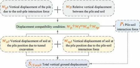
Fig.1.Logic diagram of the methodology.
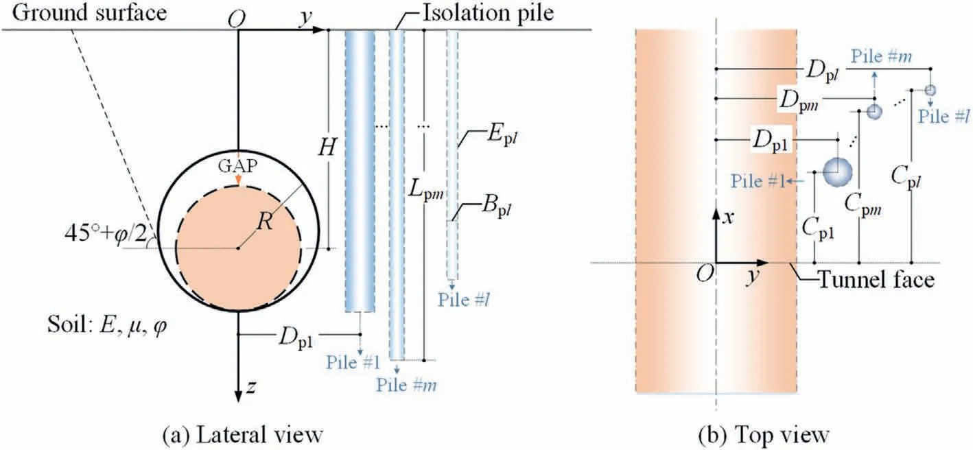
Fig.2.Layout of tunnel and isolation piles.
where Sz(y,z)is the vertical ground displacement at point(y,z),R is the excavation radius of the tunnel, H is the buried depth of the tunnel spring line(Fig.2),μ is the Poisson’s ratio of the soil,φ is the internal friction angle of the soil, and0is the ground volume loss caused by tunnel excavation.Ground volume loss can be calculated by
where Vsis the difference between the volume of the tunnel excavated per unit length along the tunneling direction and the volume after the excavation boundary converges, and GAP is the vertical displacement of the highest point of the excavation boundary (Lee et al.,1992; Cao et al., 2020a; Soomro, 2021).
The above-listed calculation formula of ground deformation is based on the plane assumption,i.e.the spatial effect of tunneling is not considered.Ground deformation induced by tunneling is a typical three-dimensional (3D) problem.For this reason, the twodimensional (2D) formula can be extended to the 3D state if the law of ground volume loss changes along the tunneling direction is obtained.According to this idea,3D vertical ground displacements Sz(x,y,z) at point (x,y,z) can be calculated by
where (x) is the ground volume loss at different positions along the tunneling direction.According to related research (Sagaseta,1987; Liang et al., 2015), this variable can be expressed by
As shown in Eq.(4),when x = 0,the ground volume loss at the tunnel face is half of the maximum stable volume loss (0), which means that the maximum ground settlement at the tunnel face is half of the maximum ground settlement far behind the tunnel face.In fact, this result is usually not supported by actual engineering data.For instance, measured data have found that ground settlements at the tunnel face are usually less than 50%of the maximum stable settlements(Standing and Selemetas,2013).In addition,field measurements have revealed that ground settlements at a position near the length of the shield machine from the tunnel face can almost reach 50% of the stable settlements (Wan et al., 2017).Therefore,it is necessary to modify Eq.(4)to match the actual cases,and the modified longitudinal ground volume loss can be expressed as
where x0is the position (longitudinal coordinate) at which the ground volume loss is half of the stable ground volume loss.For the case recorded by Wan et al.(2017),x0= -L,and L is the length of the shield machine.For the case x0→+∞, (x) =0,the 3D state is transformed into a 2D state.In this paper, these two cases will be used as the input of ground deformation to analyze the pile-soil interaction.
2.2.Solution of vertical displacements for the Mindlin problem
The pile-soil interaction is realized by the interaction force between the pile and surrounding soil.The force of the pile on the soil is equal to the force of the soil on the pile, but the direction is opposite.When the soil is taken as the research object,the force of the pile on the soil is regarded as the external load.In this case,solving the soil deformation can be modeled as a Mindlin problem(Fig.3a).The Mindlin problem can be simply described as follows:the deformation and stress of an elastic medium due to a concentrated force are applied to an arbitrary point within the elastic medium in semi-infinite space(Mindlin,1936,Fig.3a).The vertical displacement uzat point(x,y,z)due to a concentrated force P being applied at point (0,0,c) can be calculated by
where G is the shear modulus of the soil, L1is the distance of the action point of the concentrated force from the point to be evaluated,and L2is the distance of the mirror point of the action point of the concentrated force from the point to be evaluated (Fig.3a).These two distances can be calculated by
It can be seen in Fig.3a that Eq.(6)can only calculate the vertical displacement caused by a concentrated force acting on a certain point on the coordinate axis, which has certain limitations on the application of the solution.Therefore, this solution should be transformed into a general form.To this end, the following transformation relations are implemented (Fig.3b):
where (ξ,ζ,η) is the action point of the concentrated force after transformation.The value of the concentrated force P is converted into a unit concentrated force,and the shear modulus of the soil G is replaced by the elastic modulus E and Poisson’s ratio μ of the soil.Through the above transformation, the vertical displacement uz(ξ,ζ,η,x,y,z) at arbitrary point (x,y,z) caused by a unit concentrated force applied at another arbitrary point (ξ,ζ,η) can be calculated by
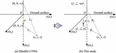
Fig.3.Mindlin problem.
where R1is the distance of the action point of the concentrated force from the point to be evaluated, and R2is the distance of the mirror point of the action point of the concentrated force from the point to be evaluated (Fig.3b).These two distances can be calculated by
When analyzing the pile-soil interaction to solve the unknown interaction forces, only the soil deformation at the position of the pile and the pile deformation need to be considered in the analysis process.Therefore,the applied point of the concentrated forces(the forces of the pile on the soil)and the point to be evaluated share the common abscissa and ordinate,i.e.x = ξ = Cp,y = ζ = Dp.The two distances can be simplified as R1= |z-η| and R2= |z + η|.The general form of Eq.(9)when the pile-soil interaction analysis is performed can be simplified as
The above equation is important in the following pile-soil interaction analysis.
2.3.Mechanical model for singe pile-soil vertical interaction
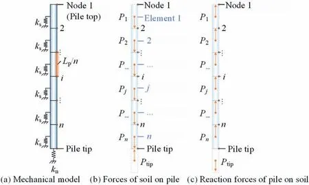
Fig.4.Mechanical model for pile-soil vertical interaction (schematic diagram).
The mechanical model for single pile-soil vertical interaction is shown in Fig.4a.The Lp-long pile is divided into n elements,and the length of each element is Lp/n.Therefore,there are a total of n+ 1 nodes on the pile,and the number of nodes ranges from 1 to n+ 1.The number of nodes is represented by i, the first node is the pile top,and the(n+1)th node is the pile tip.The pile-soil interaction is simulated by the pile shaft-surrounding soil springs(the stiffness of these springs is ks) and the pile tip-supporting soil spring (the stiffness of this spring is kn).The internal forces of the springs are the pile-soil interaction forces.The spring is located at the center of each element, where the shaft springs are located at the center of the 1 to nth element, and the tip spring is located at the center of the (n+1) th virtual element.Assuming that the surrounding soil moves downward on the pile,it will produce downward forces(P1,…,Pj,…,Pn, the number of forces is represented by j) on the pile shaft(Fig.4b and c).To maintain balance,the supporting soil at the pile tip will produce an upward force(i.e.Ptip= ∑nj=1Pj)(note that the direction of the actual forces depends on the relative motion of the soil and the pile; therefore, the direction of the interaction forces may be different from the assumption).If the calculated forces are represented by a negative number,then the direction of the forces are opposite to the assumed direction.
Ground movements induced by tunnel excavation will drive the isolation piles to move and deform.Synchronously, the isolation piles also resist dragging from the soil.Therefore, the dragging of the soil and the resistance of the pile together make the entire pilesoil system to a balanced state.Naturally, the pile and the soil satisfy the displacement compatibility condition at the arbitrary i th node(i ranges from 1 to n+ 1), which can be represented by
where the left side of the equation is the pile displacement at the ith node,and the right side of the equation is the soil displacement at the ith node.The pile displacements are composed of two parts;one is represented by the compression or tensile displacements of the pile wpi, and the other is represented by the compression or tensile displacements of the springs wfi.The soil displacements are also composed of two parts, one of which is the soil displacement induced by tunnel excavation wsti, and the second is the soil displacement caused by the forces of the pile on the soil wspi.These four variables can be calculated by
where wTis the vertical displacement of the pile tip;Njis the axial force of the jth element; Apis the area of the cross-section of the pile,which is equal to πBp2/4;ziis the z-coordinate of the ith node;and Sz(Cp,Dp,zi) is the ground vertical displacement due to tunneling at the ith node, which can be calculated by Eq.(3);ηjis the z-coordinate of the center of jth element;ηTis the z-coordinate of the (n+1) th virtual element; f(ηT,zi) is the ground vertical displacements at the ith node due to a unit concentrated force applied at the center of the(n+1)th virtual element;and f(ηj,zi)is the ground vertical displacements at the ith node due to a unit concentrated force applied at the jth element.
Expanding Eq.(12) at n+1 nodes to obtain n+1 equations,each of which contains the unknown parameter wT.Substituting the(n+1)th equation into the former n(from 1 to n)equations can eliminate wTand further obtain the following matrix equation,i.e.
where {P} is an n×1 column vector for the pile-soil interaction force, {P} = {P1,P2,…,Pj,…,Pn-1,Pn}T; {ψ} is an n× 1 column vector for the relative ground vertical displacements, {ψ} ={ψ1,ψ2,…,ψi,…,ψn-1,ψn}T;and[δ]is an n×n analogous flexibility matrix.The associated parameters in these vectors and matrix can be calculated by
where i∈[1,n], j∈[1,n], and zTis the z-coordinate of the (n+1) th node(pile tip).Reorganizing Eq.(14),the unknown column vector for the pile-soil interaction force can be obtained by
When the pile-soil interaction forces are obtained, the ground vertical displacements caused by the interaction forces can therefore be calculated.The total vertical ground displacements can eventually be calculated by superimposing the ground displacements due to the tunnel excavation.The total vertical displacements SzTotal(x,y,z) at arbitrary point (x,y,z) can be expressed by

2.4.Investigation of the case for the pile group
The above research focuses on the single pile-soil vertical interaction.In actual engineering,isolation piles are usually served in the form of pile rows (one form of the pile groups).Therefore,when tunnel excavation induces soil deformation, the deformed soil will interact with the entire pile row system.Describing the pile-soil interaction in this case and calculating the total vertical ground displacements are important.
To investigate a more general situation, the pile group-soil interaction model is established, as shown in Fig.5.The pile group system contains a total of l piles,each of which has a different length,diameter,and relative position to the tunnel.Similar to the single pile analysis, each pile in the pile system is divided into n elements(including the(n+1)th virtual element)and n+1 nodes.The z-coordinate of the first node of the m th (m∈[1, l]) pile is represented by zn(m-1)+1.By analogy, the z-coordinate of the i th node is represented by zn(m-1)+i, and the z-coordinate of the n th node is represented by znm.The z-coordinate of the(n+1)th node is represented by zTminstead of znm+1.The z-coordinate of the center of the first element of the k th(k∈[1,l])pile is represented by ηn(k-1)+1.By analogy, the z-coordinate of the center of the j th element is represented by ηn(k-1)+j, and the z-coordinate of the center of the n th element is represented by ηnk.The z-coordinate of the center of the (n+1) th virtual element is represented by ηTkinstead of ηnk+1.
Similar to the single pile-soil interaction, the pile group-soil interaction also needs to satisfy the displacement compatibility condition,i.e.the condition must be established at the same time at a total of l(n+1) nodes of l piles.Among them, the four relevant variables can be calculated by
where wTmis the vertical displacement of the m th pile tip and Apmis the area of the cross section of the m th pile, which is equal to πBpm2/4.Other variables can be explained by analogy with the previous variables.Expanding Eq.(18)at l(n+1)nodes of l piles to obtain l(n+1) equations in total; among them, a total of n+ 1 equations can be listed on each pile.On the m th pile,substituting the equations listed at the(n+1)th node into the former n(from 1 to n) equations can eliminate the unknown parameter wTm.Through further sorting, the following matrix equation can be obtained:

where m∈[1,l], k∈[1,l], i∈[n(m - 1) + 1,nm], j∈[n(k - 1) + 1,nk],and zTmis the z-coordinate of the (n+1) th node of the m th pile.Reorganizing Eq.(20),the unknown column vector for pile groupsoil interaction forces can be obtained by
Consistent with the previous approach,the total vertical ground displacements can eventually be calculated by

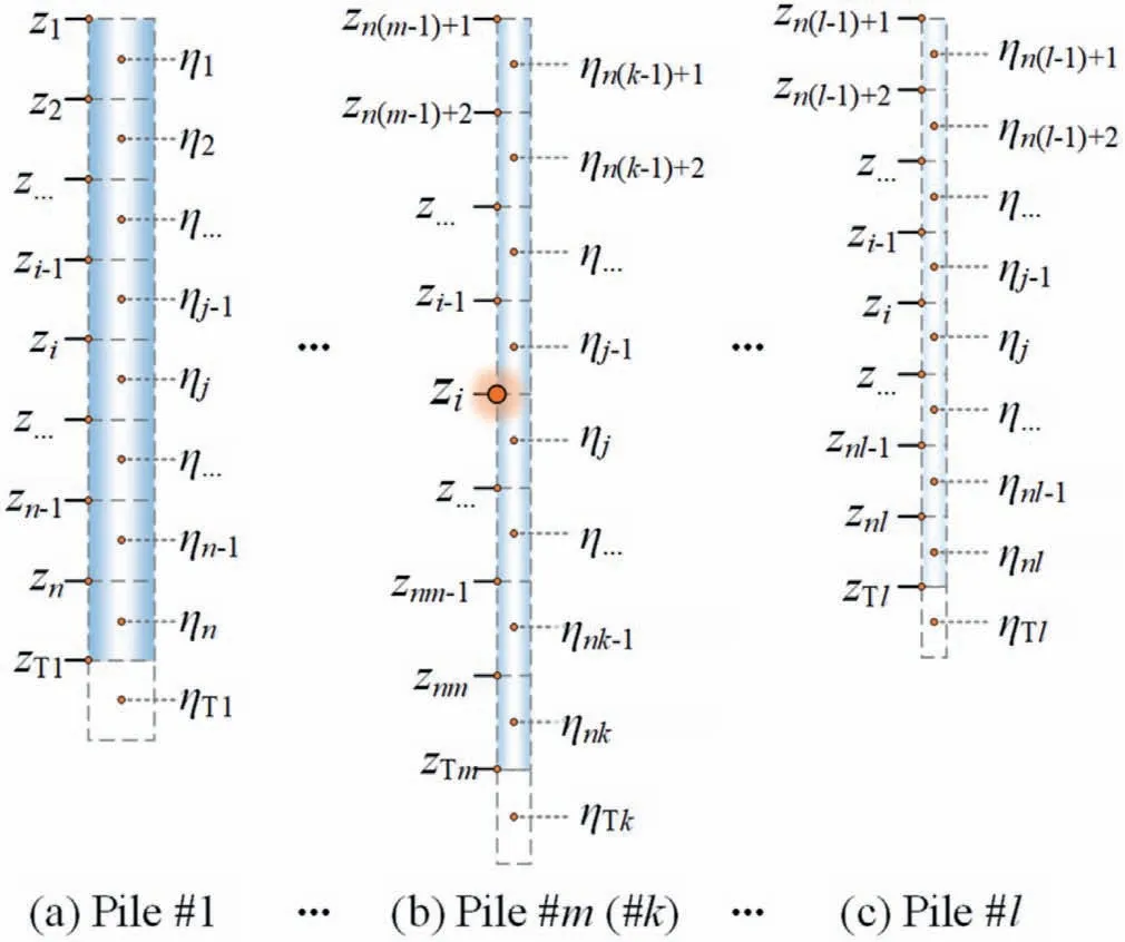
Fig.5.Calculation model for l-pile group (n elements for a pile, l piles in the pile group).
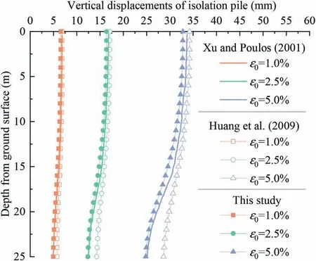
Fig.6.Vertical displacements of single pile.
3.Verification
To verify the proposed method in this paper, we compare the calculated results using the proposed method with those using the existing theoretical methods, including BEM and EFM.It is worth noting that the existing method only calculates the vertical displacement and axial force of the pile and does not take into account the vertical ground displacement at the pile position,let alone the displacement in semi-infinite space.However, according to the displacement compatibility condition, the vertical displacement of the pile is equal to that of the ground at the pile position (no slip exists at the pile-soil interface).Therefore, the proposed method can also be verified indirectly based on the displacement and internal force of the pile.To facilitate understanding,we analyze the conditions of a single pile and pile group separately.
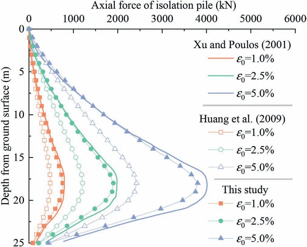
Fig.7.Axial forces of single pile.
3.1.Single pile condition
Xu and Poulos(2001)presented a case of a single pile affected by tunnel excavation and calculated the vertical displacement and axial force of the pile using the GEPAN program,which is based on BEM.The relevant parameters for this case are as follows: R =3 m, H = 20 m,0= 1%,3%,5%, E = 24 MPa, μ = 0.5, Bp=0.5 m, Lp= 25 m, Dp= 4.5 m, and Ep= 30 GPa.After that,Huang et al.(2009) estimated the vertical displacement and axial force of the pile based on the abovementioned case using EFM.For the proposed method in this study, additional parameters are also needed, such as x0→+∞(set to a large value), φ = 0°, ks=1020N/m,kn= 1020N/m,Cp= 5 m,and n = 25.The calculated vertical displacement and axial force of the pile among these three methods are shown in Figs.6 and 7, respectively.
The comparison shows that the results calculated by the proposed method are close to those calculated by Xu and Poulos(2001)using the GEPAN program, while the results calculated by Huang et al.(2009) have some deviation from those calculated by Xu and Poulos (2001).This is mainly because although the proposed method is more simplified than the BEM, both methods belong to the elastic continuum method.That is,not only is the displacement compatibility condition at the pile-soil interface considered, but the continuous deformation of the soil within the semi-infinite space is also considered.Therefore, the results calculated in this paper are closer to the results calculated by the BEM.EFM is an approximate method that only considers the compatibility condition at the pile-soil interface and does not consider the continuous deformation of the soil within the semi-infinite space.Therefore,there is a certain deviation between the results calculated by EFM and those calculated by the elastic continuum method.Based on the above analysis, it can be seen that the simplified elastic continuum method proposed in this paper is reasonable and can be used for the estimation of the mechanical responses of a single pile due to tunnel excavation.At the same time,in addition to the above two methods, the proposed method can calculate the vertical ground displacements after being restrained by the isolation pile,which is also the research theme and focus of this paper.
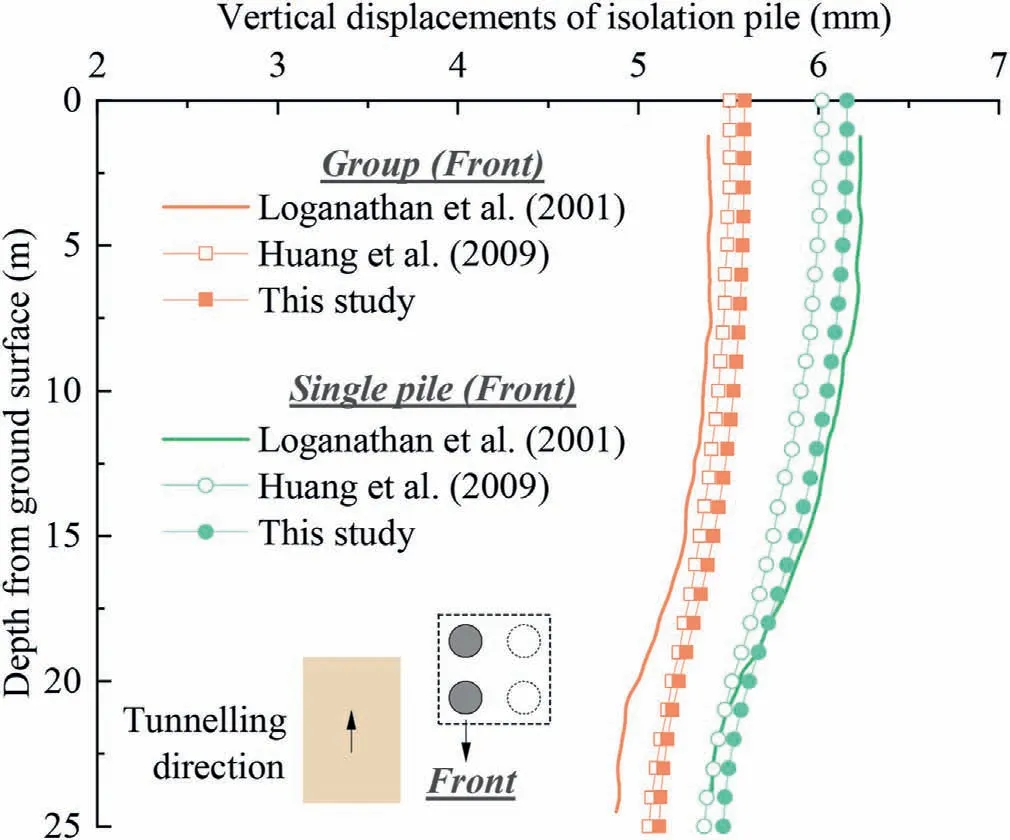
Fig.8.Vertical displacements of front pile in pile group.
3.2.Pile group condition
Loganathan et al.(2001) also presented a case of a 2×2 pile group affected by tunnel excavation and calculated the vertical displacement and axial force of the pile element using the GEPAN program.The relevant parameters for this case are as follows:R =3 m, H = 20 m,0= 1%, E = 24 MPa, μ = 0.5, Bp1= Bp2=Bp3= Bp4= 0.8 m, Lp1= Lp2= Lp3= Lp4= 25 m, Dp1=Dp2= 4.5 m, Dp3= Dp4= 6.9 m, and Ep1= Ep2= Ep3=Ep4= 30 GPa.Huang et al.(2009)also studied this case using the EFM and conducted a comparison with previous research.For the proposed method in this study, additional parameters are also needed: x0→+∞(set to a large value), φ = 0°, ks= 1020N/m,kn= 1020N/m,Cp1= Cp3= 5 m,Cp2= Cp4= 7.4 m,and n =25.The calculated vertical displacements of the front pile and rear pile among these three methods are shown in Figs.8 and 9,respectively.The calculated axial forces of the front pile and rear pile among these three methods are shown in Figs.10 and 11,respectively.
The results show that the vertical displacement and axial force of the pile in the form of a single pile are significantly larger than those of the pile in the form of the pile group at the same position.This is mainly because the additional loads caused by tunnel excavation borne by a certain pile element in the pile group can be shared by other pile elements, while the single pile needs to bear these additional loads alone.The results also indicate that the vertical displacement and axial force of the front pile are significantly larger than those of the rear pile in a pile group, which is mainly related to the tunneling-induced greenfield displacements.That is, the closer the distance to the tunnel, the greater the additional load imposed by the ground on the pile,and vice versa.The comparison of the three methods shows that the calculated results using the proposed method are close to those using the GEPAN program, but the deviation of the calculated results of EFM is relatively large.It can be seen from the analysis of pile group conditions that, as a simplified elastic continuum method, the proposed method can be verified.
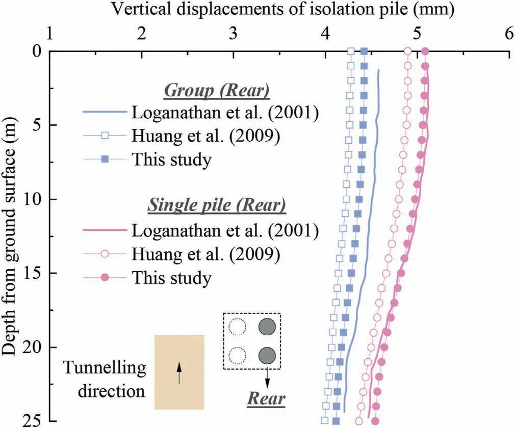
Fig.9.Vertical displacements of rear pile in pile group.
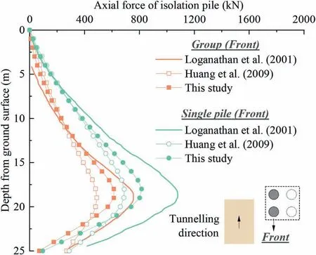
Fig.10.Axial forces of front pile in pile group.
4.Mechanism analysis
The above sections focus on the methodology and its validation.This section will analyze the restraint effect of the isolation piles on tunneling-induced vertical ground displacements to reveal the mechanism of the isolation pile in service.
4.1.Restraining mechanism of isolation piles on vertical ground displacements
In the process of analyzing the mechanism, the case of a single pile is taken as the object first, and then the case of row piles is analyzed.The relevant parameters of the case of a single pile are as follows: R = 5 m, H = 15 m,0= 1%, E = 100 MPa, μ = 0.5,Bp= 1 m,Lp= 20 m,Dp= 10 m,Ep= 200 GPa,x0→+∞(set to a large value),φ = 0°,ks= 1015N/m,kn= 1015N/m,Cp=5 m, and n = 20.The calculated 3D vertical ground surface displacements are shown in Fig.12,in which the displacements due to tunneling (Fig.12a), displacements due to pile-soil interaction forces(Fig.12b)and the total displacements after the superposition of the first two (Fig.12c) are demonstrated.The results show that the isolation piles restrain the downward movement of the ground by interacting with the soil,which causes the settlement trough to change from the original symmetrical shape about the tunnel axis to an asymmetrical shape.The soil at the location of the isolation pile is subjected to the greatest restraint effect, and the restraint effect decreases to zero when moving away from the isolation pile.
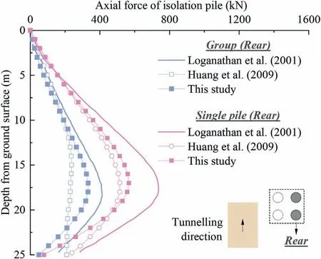
Fig.11.Axial forces of rear pile in pile group.
To further analyze the mechanism by which the isolation pile exerts its restraint effect, we demonstrate the vertical ground surface displacement on the cross-section at which the isolation pile is located,the vertical ground displacement along the pile shaft, and the pile-soil interaction force,as shown in Figs.13-15,respectively.As shown in Fig.13,the upward‘lifting effect’of the isolation pile on the soil is relatively obvious, and this effect can play an important role in restraining the vertical movement of the soil.In addition,as mentioned above, the settlement trough of the ground surface shows a certain asymmetry.
As shown in Fig.14, when isolation piles are not present, the greenfield ground vertical displacement shows a nonlinear decrease in general as it changes from the ground surface to the position at the tunnel invert.When isolation piles are present,the ground settlement above a certain position above the tunnel spring line is significantly restrained (i.e.upward restraint effect or positive restraint effect).This restraint effect is closely related to the greenfield settlement, i.e.the larger the greenfield settlement is,the greater the positive restraint effect of the isolation pile on ground settlement, reflecting the characteristics of the isolation pile, which is ’strong when it is strong’.On the other hand, the ground settlement below a certain position above the tunnel spring line is promoted downward (i.e.downward restraint effect or negative restraint effect); the smaller the greenfield settlement is,the greater the negative restraint effect of the isolation pile on ground settlement.The reason for this phenomenon may be that the ground settlement above the tunnel spring line is relatively large, which will drive the pile downward and cause compression deformation of the pile.As the deformation stiffness of the isolation pile is larger compared with the soil,it shows a more obvious rigid movement, as shown in Fig.14, showing a more obvious overall settlement(i.e.deformation is not so obvious).Therefore,when the overall settlement of the isolation pile is greater than the ground settlement below the tunnel spring line, the isolation pile will in turn hold down and promote the downward movement of the ground, thus increasing the ground settlement here.When the relative displacement is more obvious,the negative restraint effect is more obvious.
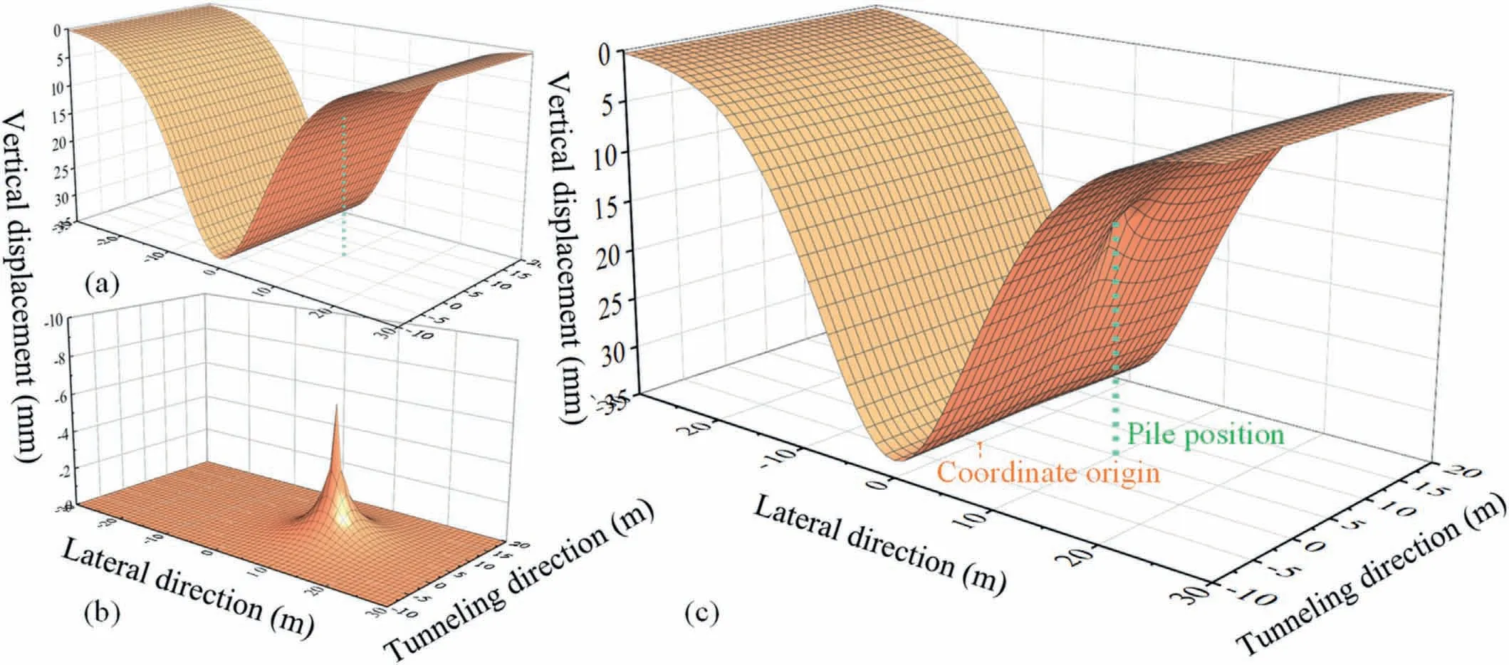
Fig.12.Calculated vertical ground surface displacement: (a) Displacement due to tunneling, (b) Displacement due to pile-soil interaction force, and (c) Total displacement.
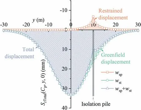
Fig.13.Vertical ground surface displacement on the cross-section at which isolation pile is located.
Furthermore, from the pile-soil interaction force shown in Fig.15, it can be seen that the force of the pile on the soil above a certain location above the tunnel spring line is upward, and therefore, the pile exerts an upward restraint effect on the soil(Zone A in Fig.15,i.e.positive restraint effect);the force of the pile on the soil below this location is downward,and therefore,the pile exerts a downward restraint effect on the soil(Zone B in Fig.15,i.e.negative restraint effect), which corresponds to the displacement results shown in Fig.14.In summary, the mechanism of the isolation pile in service can be summarized as follows: due to the notable difference in the deformation stiffness of the isolation pile and the soil, as well as the difference in their initial relative displacement at different positions, the isolation pile exerts a positive or negative restraint effect on the soil accordingly,and the positive and negative restraint effects jointly drive the ground vertical displacement along the depth direction from the original tunneling-induced nonlinear variation situation to a relatively uniform situation.
4.2.Stiffness of the pile shaft-soil interface ks on the restraint effect
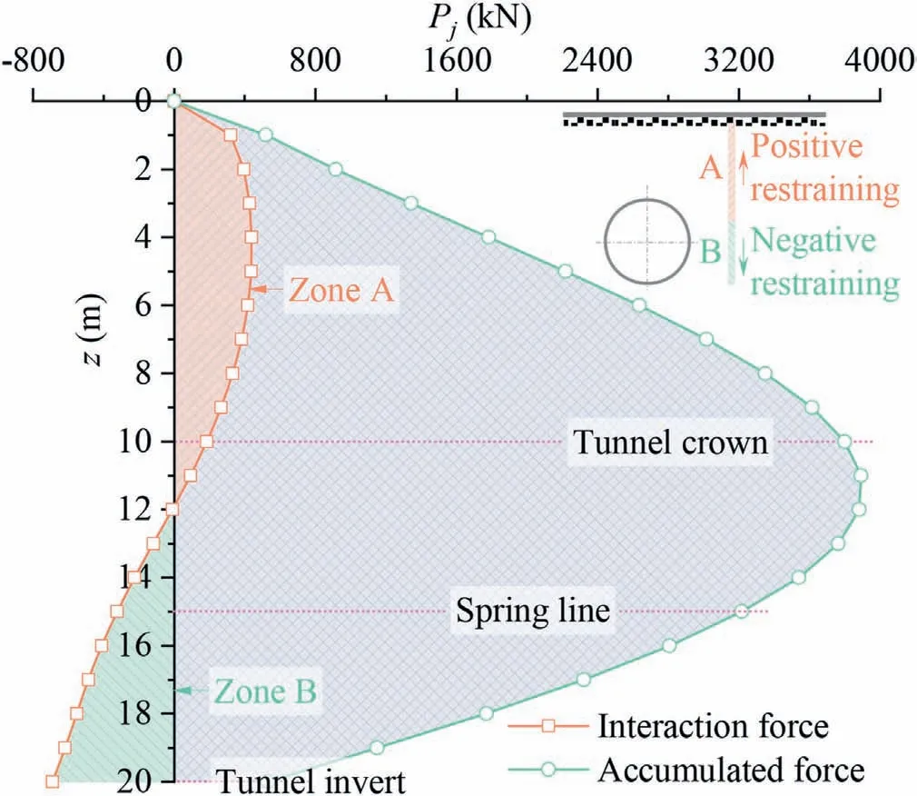
Fig.15.Pile-soil interaction force.
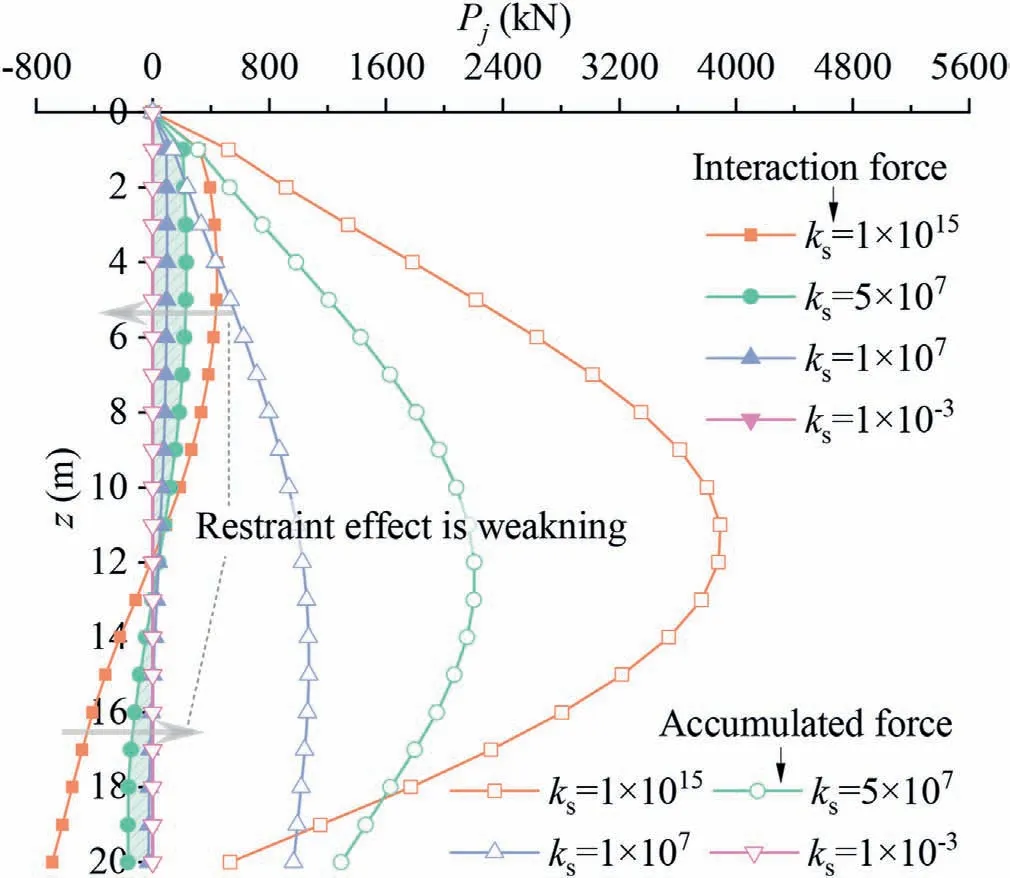
Fig.16.Pile-soil interaction force under different stiffnesses at pile shaft-soil interface.
Whether the deformation stiffness of the isolation pile-soil interface(manifested by the uncoordinated deformation of the pile and the soil at the same location)has an effect on the restraint role of the isolation pile needs further in-depth investigation.Among them,the interface includes two parts:the pile shaft-soil interface and the pile tip-soil interface.First, looking at the pile shaft-soil interface, the deformation stiffness ksis set to different values:ks= 1015N/m,ks= 5×10⁷N/m,ks= 1×10⁷N/m,ks= 1×10⁻³N/m, and other related parameters listed in Section 4.1 are kept constant.
The pile-soil interaction force under different stiffnesses at the pile shaft-soil interface is shown in Fig.16.The results show that as the stiffness of the pile shaft-soil interface kschanges from nearly infinite to nearly zero, the interaction force between the pile and the soil gradually decreases to zero,i.e.the interaction between the two gradually weakens, and both the positive and negative restraint effects of the isolation pile on the ground also show a trend of weakening.The vertical displacement of the ground and pile under different stiffnesses at the pile shaft-soil interface is shown in Fig.17.The results likewise indicate that as ksvaries from near infinity to near 0, the restraint effect gradually weakens, which leads to sliding between the pile shaft and the surrounding soil.When kstends to infinity,the pile shaft-soil interface is completely bonded(the deformation of the soil and the pile are the same,and the two curves in Fig.17 overlap).When kstends to 0,the pile and the soil are completely sliding;at this time,the displacement of the soil is still the greenfield displacement caused by the tunnel excavation,and the displacement of the pile is the overall displacement(the same as the displacement of the soil at the end of the pile)without compression deformation.Therefore, when ksis between infinity and zero, the displacement between the pile shaft and the surrounding soil is between completely coordinated and completely uncoordinated.
4.3.Stiffness of the pile tip-soil interface kn on the restraint effect
Then, looking at the pile tip-soil interface, the deformation stiffness knis set to different values: kn= 1015N/m, kn=109N/m, kn= 108N/m, kn= 10-3N/m, and other related parameters listed in Section 4.1 are kept constant.The pile-soil interaction force under different stiffnesses at the pile tip-soil interface is shown in Fig.18.The results show that when knvaries from near infinity to near 0,the pile shaft-soil interaction force in the local range near the pile tip gradually increases, and the negative restraint effect shows a trend of gradual strengthening.However, due to the gradual decrease in kn, the interaction force between the pile tip and soil is gradually reduced, and when knis close to 0, there is no interaction between the pile tip and the surrounding soil.The vertical displacement of the ground and pile under different stiffnesses at the pile tip-soil interface is shown in Fig.19.The results likewise indicate that because ksis large, then the pile shaft deforms in coordination with the surrounding soil,i.e.no relative slip occurs(the soil deforms in line with the pile,and the two curves in Fig.19 overlap).However, when kngradually decreases,the displacement of the pile tip is no longer consistent with the displacement of the supporting soil, and the pile will be embedded into the supporting soil.When the pile tip loses the support of the soil,the restraint effect will be weakened;therefore,ensuring the coordinated deformation of the pile tip and the supporting soil can enhance the restraint effect.
4.4.Restraint performance of pile rows as isolation piles
The isolation piles are usually in service in the form of pile rows,in which the pile elements are usually embedded in the ground at regular intervals along the tunneling direction before the tunnel excavation.When tunneling, there are differences in the ground deformation at different longitudinal positions from the tunnel face,which is the so-called spatial effect of ground displacement,as mentioned in Section 2.1.Therefore, there is a difference in the initial greenfield ground displacement at each pile element,which leads to a difference in the restraint effect exerted by each pile.To investigate the restraint performance of pile rows as isolation piles,two cases of constant volume loss and changing volume loss along the tunneling direction are assessed.The layout of the tunnel and pile rows is shown in Fig.20, and the relevant parameters are as follows: R = 5 m, H = 15 m,0= 1%, E = 100 MPa, μ = 0.5,Bpm= 1 m, Lpm= 20 m, Dpm= 10 m, Epm= 200 GPa, φ = 0°,ks= 1015N/m,kn= 1015N/m,Cpm= (m -1)s m,n = 20,l =5, m∈[1,l], and s = 2.5Bpm.For the case of constant volume loss,x0→+ ∞, and for the case of changing volume loss, x0= -L and L = 10 m.
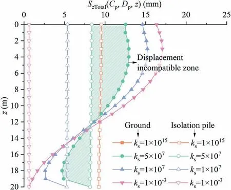
Fig.17.Vertical displacement of ground and pile under different stiffnesses at pile shaft-soil interface.
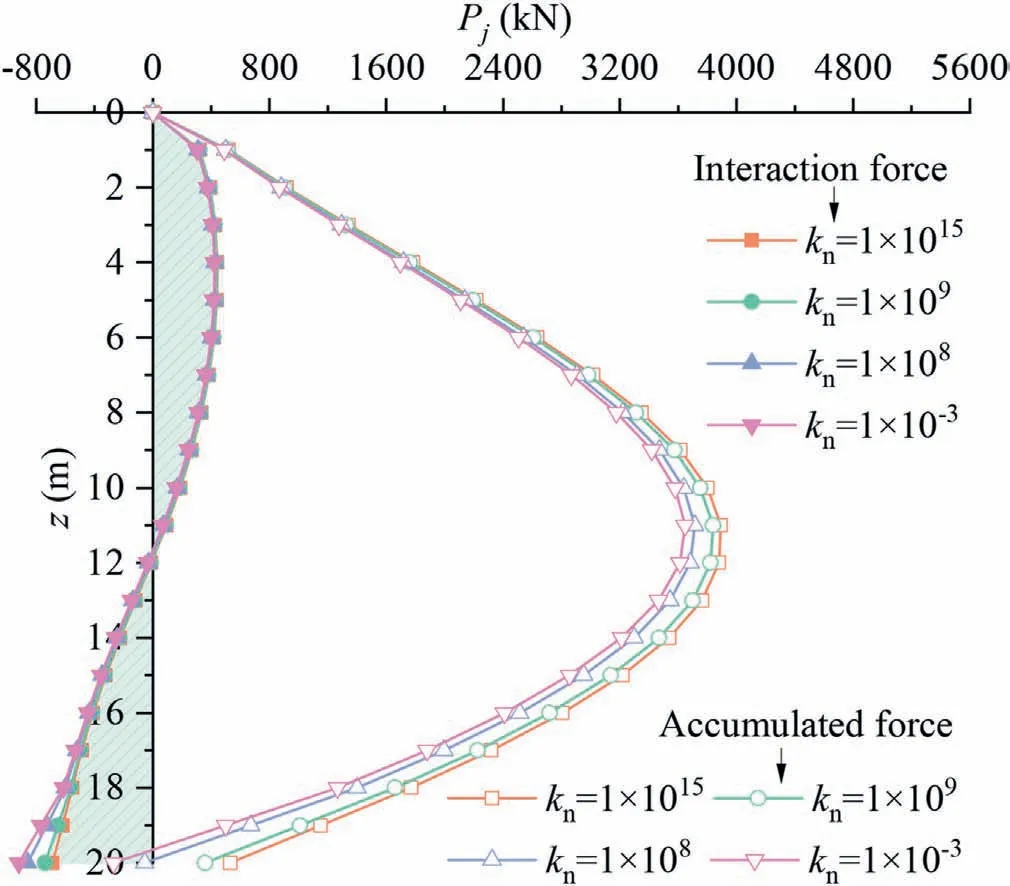
Fig.18.Pile-soil interaction force under different stiffnesses at pile tip-soil interface.
(1) Constant volume loss along the tunneling direction
The calculated contours of vertical ground surface displacement due to tunneling and due to pile-soil interaction force under constant volume loss conditions are shown in Fig.21a and 22a,respectively.The results show that since the volume loss is uniformly distributed along the tunneling direction, the vertical greenfield ground surface displacement also shows a uniform distribution pattern along the tunneling direction.Similarly, for the ground displacement caused by the pile-soil interaction force,with the lateral axis(y-direction)and the longitudinal axis(x-direction)passing through the intermediate pile (pile #3) as the symmetry axes,it is also symmetrically distributed,where the displacement is the largest at the intermediate pile (pile #3) and gradually decreases away from it.The calculated contour of the total vertical ground surface displacement is shown in Fig.23a.The results clearly showed that the pile rows confined the vertical ground displacement caused by the tunnel excavation to the inner side of the isolation piles and effectively prevented the vertical ground displacement from expanding further toward the outer side of the isolation piles.Therefore, as a protective measure, the isolation piles can effectively protect the existing structures on the outside of the isolation piles.
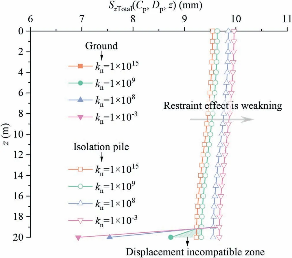
Fig.19.Vertical displacement of ground and pile under different stiffnesses at pile tipsoil interface.
(2) Changing volume loss along the tunneling direction
The calculated contours of vertical ground surface displacement due to tunneling and due to pile-soil interaction force under changing volume loss conditions are shown in Fig.21b and 22b,respectively.Compared to the constant volume loss condition,since the volume loss is no longer uniformly distributed along the tunneling direction, the vertical greenfield ground surface displacement no longer shows a uniform distribution pattern along the tunneling direction.As a result, the vertical ground displacement caused by the pile-soil interaction force is no longer symmetrically distributed with the lateral axis (y-direction) through the intermediate pile (pile #3) as the axis of symmetry.The law is that the closer the pile element is to the tunnel face,the greater the greenfield ground displacement, and the greater the ground displacement is restrained by the pile, and vice versa.
The calculated contour of the total vertical ground surface displacement under changing volume loss conditions is shown in Fig.23b.Compared to the constant volume loss condition,since the greenfield ground displacements at different locations in front of the tunnel face are relatively small and different under the changing volume loss condition, the pile-soil interaction is weak,which results in the isolation piles not exerting their full restraint capacity, i.e.the ground displacement caused by the tunnel excavation was not effectively confined to the inner side of the isolation piles.As the tunnel face gradually advances, the restraint capacity of the isolation piles will be continuously developed, and the ground displacement caused by the tunnel excavation is similarly confined to the inner side of the isolation piles when the volume loss is kept stable.
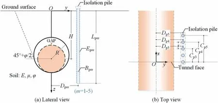
Fig.20.Layout of tunnel and pile rows.
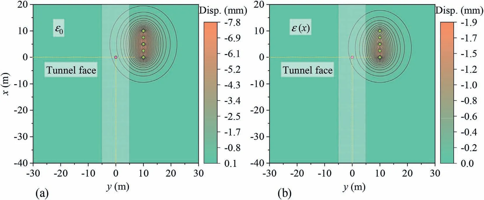
Fig.22.Calculated contour maps of vertical ground surface displacement due to pile-soil interaction force under(a)constant volume loss condition,and(b)changing volume loss condition.
In this paper,we mainly elaborate on the restraining mechanism of isolation piles on vertical ground displacements due to tunneling and perform a preliminary analysis of the restraint performance of the pile rows as isolation piles.In fact,the most fundamental goal of isolation piles is to protect existing underground structures,such as existing tunnels, existing pipelines and existing pile foundations.Therefore, subsequent studies should focus on the coupling analysis between the isolation piles and the protected structures, as well as the nonlinearity of the soil and the soil-structure interface,which deserve to be studied in depth but are beyond the scope of this paper.
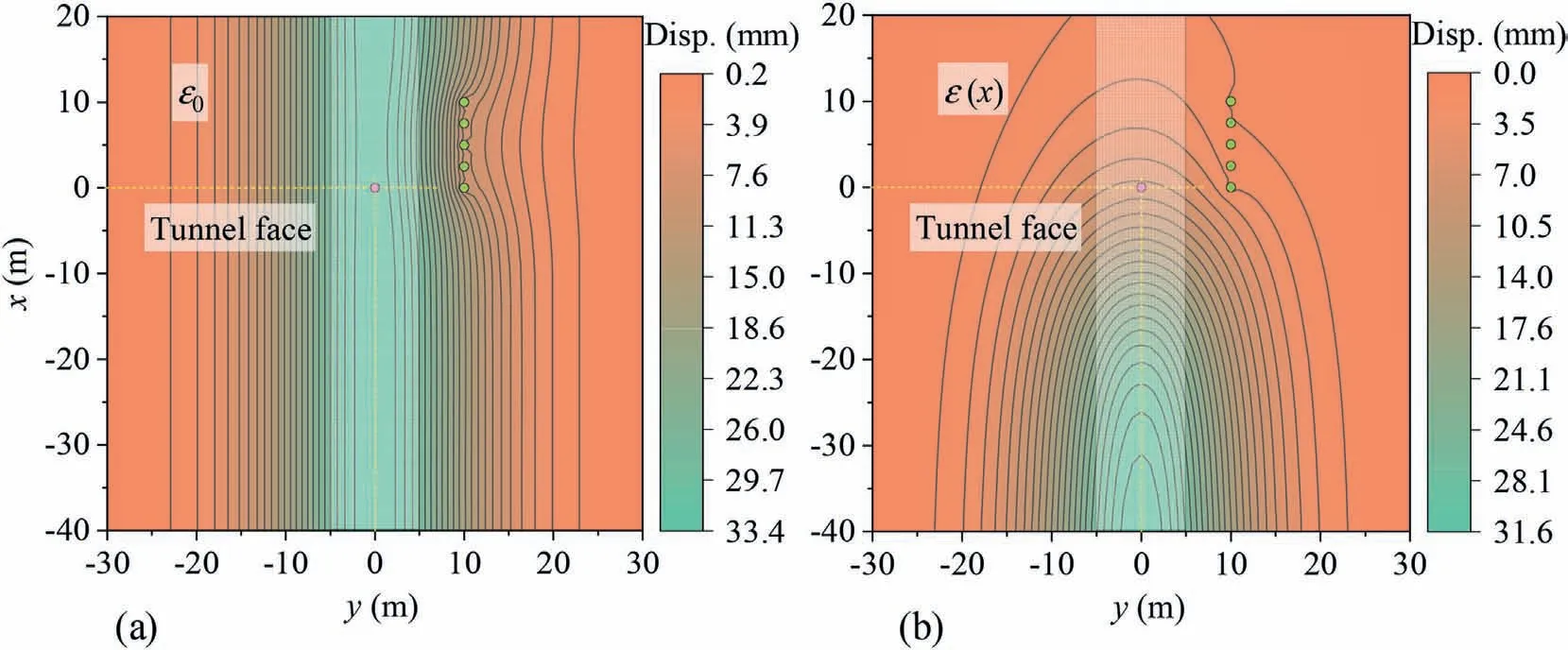
Fig.23.Calculated contour maps of total vertical ground surface displacement under (a) constant volume loss condition, and (b) changing volume loss condition.
5.Conclusions
This paper presents a simplified elastic continuum method for calculating the restraint effect of isolation piles on tunnelinginduced vertical ground displacement, which can consider not only the relative sliding of the pile-soil interface but also the pile row-soil interaction.The proposed method is verified by comparisons with existing theoretical methods, including BEM and EFM.Based on the proposed theoretical method, the paper reveals the mechanism of isolation piles in service and investigates the restraint performance of pile rows as isolation piles under different ground volume losses along the tunneling direction.The main conclusions obtained are as follows:
(1) The mechanism of the isolation pile in service can be summarized as follows: due to the notable difference in the deformation stiffness of the isolation pile and the soil,as well as the difference in their initial relative displacement at different positions, the isolation pile exerts a positive or negative restraint effect on the soil accordingly, and the positive and negative restraint effects jointly drive the ground vertical displacement along the depth direction from the original tunneling-induced nonlinear variation situation to a relatively uniform situation.
(2) The stiffness of the pile-soil interface, including the pile shaft-surrounding soil interface and pile tip-supporting soil interface, describes the strength of the pile-soil interaction.The smaller the stiffness of the pile-soil interface is, the smaller the pile-soil interaction force,the larger the relative displacement between the pile and the soil,and the smaller the positive and negative restraint effects exerted by the isolated piles.In the actual project,the bonding between the pile and the surrounding soil and the supporting capacity of the soil at the pile tip should be enhanced as much as possible, which will help to improve the overall restraint performance of the isolation pile.
(3) When the ground volume loss changes along the tunneling direction, the pile rows in front of the tunnel face cannot exert their full restraint capacity due to the insignificant greenfield ground displacement.As the tunnel face gradually advances, the pile rows can continuously develop their restraint capacity to confine the vertical ground displacement caused by the tunnel excavation to the inner side of the isolation piles and effectively prevent the vertical ground displacement from expanding further toward the outer side of the isolation piles.
Declaration of competing interest
The authors declare that they have no known competing financial interests or personal relationships that could have appeared to influence the work reported in this paper.
Acknowledgments
The authors gratefully acknowledge the financial support by the National Natural Science Foundation of China(Grant Nos.52108376 and 51908371) and China Postdoctoral Science Foundation (Grant No.2022T150436).
 Journal of Rock Mechanics and Geotechnical Engineering2023年10期
- Journal of Rock Mechanics and Geotechnical Engineering的其它文章
- Characterizing large-scale weak interlayer shear zones using conditional random field theory
- Displacement-based back analysis of mitigating the effects of displacement loss in underground engineering
- Investigation of long-wavelength elastic wave propagation through wet bentonite-filled rock joints
- Mechanical properties of a clay soil reinforced with rice husk under drained and undrained conditions
- Evaluation of soil fabric using elastic waves during load-unload
- Effects of non-liquefiable crust layer and superstructure mass on the response of 2 × 2 pile groups to liquefaction-induced lateral spreading
