Combined load bearing capacity of rigid piles embedded in a crossanisotropic clay deposit using 3D finite element lower bound
Ardavan Izadi, Reza Jamshidi Chenari
Department of Civil Engineering, Faculty of Engineering, University of Guilan, Rasht, Guilan, Iran
Keywords:Rigid pile Cross-anisotropy Clay Combined loading Three-dimensional finite element lower bound
ABSTRACT In this study, an iterative-based three-dimensional finite element lower bound in association with the second-order cone programming method is adopted to evaluate the limit load of a single pile embedded in cross-anisotropic soils under general loading condition.The lower bound solutions of the pile embedded in an anisotropic soil deposit can be found by formulating the element equilibrium, equilibrium of shear and normal stresses along discontinuities, boundary conditions, yield function, and optimizing the objective function through the second-order cone programming method in conjunction with an iterative-based update procedure.A general loading condition is considered to profile the expansion of the safe load in the vertical-horizontal-moment (V-H-M) space.The results of this study are compared and validated against three different cases including an isotropic lateral loading, anisotropic end bearing capacity, and a pile embedded in an isotropic soil deposit under general loading condition.A parametric study is conducted to evaluate the impact of different influencing factors.It was found that the effect of anisotropy on the variation of lateral limit load of a single pile is more pronounced than the corresponding vertical and bending moment limit loads, whereas the interface properties have more significant effects on the vertical and bending moment limit loads in comparison to the lateral limit load.
1.Introduction
Application of pile foundations in transmission of superstructure loads to the deep layers of soil is considered as one of the most versatile solutions for supporting axial,lateral and combined loads of bridge piers, wind turbines, offshore platforms, abutments and high-rise buildings (Keawsawasvong and Ukritchon, 2020; Izadi and Jamshidi Chenari, 2021, 2022).As these superstructures and their corresponding deep foundations should be designed for severe circumstances with axial loads mainly induced from the dead loads, compressive forces, uplift actions, lateral loads predominantly from wind, wave, earthquakes, and overturning moments due to eccentricity, the supporting system including piles is rarely subjected to a single loading component.Therefore, concurrent consideration of axial, lateral and moment loads, originating from different sources, seems inevitable (Arany et al., 2017; Li et al.,2020).Consequently, the prediction of pile response to the combined horizontal-vertical-moment loading is a challenging problem in the field of geotechnical engineering, which needs due consideration.
Over the last several decades,great attention has been devoted by many researchers to calculate the individual limit load of either vertically or laterally loaded piles via various numerical, analytical and experimental methods.In most of the existing solutions, the axial and lateral loads as well as bending moments of piles were considered separately by neglecting their possible interactions.Instead, piles are independently designed for each action without considering the interaction between different loadings.The studies of Broms(1964),Meyerhof et al.(1981),Murff and Hamilton(1993),Klar and Randolph (2008), Khatri and Kumar (2009), Georgiadis and Georgiadis (2010), Veiskarami et al.(2011), Yu et al.(2015),Zhang et al.(2016), Keawsawasvong and Ukritchon (2016),Ukritchon and Keawsawasvong(2018b,2020),Mortazavi Bak et al.(2021a,b),and Izadi and Jamshidi Chenari(2021,2022)are some of the most well-known solutions among many.However, this hypothesis would lead to an imperfect design,and in practice,it is notexpected to accurately simulate pile behavior, when combined loading matters (Hussien et al., 2014; Hazzar et al., 2017).
Mere and individual consideration of different loading components leaves a question about the way different loading components interact with each other.Hence, a plethora of analytical methods,numerical simulations,scaled and full-scale experimental modellings have been conducted to shed more light on this issue.The studies of Meyerhof and his co-workers are some of the earliest documents reported in the literature on the problem of pile behavior under combined loadings (Meyerhof and Ranjan, 1972;Meyerhof,1981; Meyerhof and Yalcin,1984; Meyerhof and Sastry,1985).To address the simultaneous actions of axial and lateral loads with overburden moment,they applied an inclined load with eccentricity in their small-scale pile load tests and demonstrated that the non-axial bearing capacity of the pile was strongly contingent upon the deformation characteristic of soil and pile,and the failure mechanism generated along the pile length was more complex in comparison to the individually laterally or axially loaded piles.The study of Anagnostopoulos and Georgiadis (1993)is among the first solutions on the influence of vertical load on lateral response of pile embedded in clay by using two-dimensional(2D) finite element analysis.As the interaction of soil and pile is a three-dimensional (3D) problem in nature, the accuracy of their solutions is open to question.To overcome this limitation,Yang and Jeremic(2005)conducted 3D finite element analyses to address the effect of the third dimension on the interaction effects of soil-pile interface and vertical load on the lateral behavior of piles.Li et al.(2005) conducted a parametric analysis of the impacts of different influencing factors including soil-pile interface, soil unit weight, and pile inclination angle on the combined bearing capacity of a pile embedded in single and multilayer soils.Karthigeyan et al.(2006,2007)studied combined loading effects on piles embedded in both homogeneous cohesive layers as well as non-cohesive soil layers.It can be concluded from the findings of these studies that, in the presence of vertical load, the lateral load bearing capacity of pile decreased and increased in cohesive and non-cohesive soils, respectively.They also assessed the impacts of associated and non-associated flow-rules to simulate the stressstrain behavior of soil through their finite element analyses.They further evaluated the effect of soil density on the behavior of piles under combined loading.Achmus and Thieken(2010)conducted a series of finite element analyses to evaluate the pile response in frictional soil under combined vertical and lateral loads by commercial finite element software ABAQUS.They showed that at the initial steps of vertical load application, the lateral stiffness of soil increased and consequently yielded an increase of the combined limit load of the pile.After a threshold value,the increasing vertical load brought about a significant increase of the lateral soil deformation and the soil stiffness exhibited an abrupt decrease.Lee et al.(2011)investigated the effect of soil density on the behavior of pile embedded in sand using small-scale model tests; they reported that the lateral movement of the pile under combined loading was approximately 28% higher than the corresponding purely lateral load condition.Using simplified 2D finite element analyses,Hussien et al.(2012) found that the lateral bearing capacity of the pile embedded in a sandy soil slightly increased in the presence of vertical load.They attributed this phenomenon to the increase of the confining pressure in the upper portion of the soil layer surrounding the pile length.Conte et al.(2016) pointed out the inaccuracy involved in the equivalent rigid pile method to simulate the response of piles with different flexibility indices under combined loadings.By deploying the commercial finite element software ABAQUS,they corroborated that the locations of the pivotal points,acquired from the equivalent scheme of analysis, deviated significantly from their numerical finite element results.By application of the Winkler springs, Prendergast and Gavin (2016) and Wu et al.(2018) reported the deformation response of piles under the joint action of vertical and lateral loadings, showing that the lateral displacement of piles increased with increasing vertical load.Ukritchon and Keawsawasvong (2018b) studied the undrained bearing capacity of rectangular piles under general loading using finite element limit analysis software OptumG2, and corroborated the superiority of rectangular piles over circular piles in sustaining higher lateral load and bending moment.By implementation of the finite element limit analysis software OptumG3,Graine et al.(2018,2021) calculated the undrained limit load of a short rigid pile embedded in a homogeneous clay subjected to vertical-lateral and moment loadings.Different combinations of possible loading paths were examined and the failure envelopes were reported.Furthermore,closed-form expressions were proposed and compared with their numerical finite element limit analysis equivalents.The overwhelming majority of the above-mentioned studies reported combined loading behavior of piles in mechanically isotropic soil deposits.This means that the directionality of soil strength/stiffness parameters in combined loading analysis of piles has not yet been well addressed.The current study aims at substantiating the impact of mechanical anisotropy on the failure behavior of piles subjected to general loading condition.
2.Mechanical anisotropy
Natural soil deposits exhibit different degrees of anisotropy in their mechanical properties including shear strength and stiffness parameters.The anisotropic behavior of soils can be attributed to the initial fabric, structure and particle placement during sedimentation and depositional processes in its virgin state before applying any loadings, which is called inherent anisotropy.Stressinduced anisotropy, which can occur in both isotropic and inherent anisotropic materials, introduces a secondary source of directionality in different soil properties.Overall, consideration of the mechanical anisotropy gives rise to different values of stiffness and shear strength parameters in different directions(Cassagrande and Carillo,1944;Barden,1963;Lo,1965;Bishop,1966;Ladd,1991;Abelev and Lade, 2003).Mechanical anisotropy, recognized as an inevitable characteristic of natural soil deposits, poses a serious question around the procedure to address the directionality of soil strength and stiffness properties in geotechnical stability problems.Recently,great attention has been devoted by many researchers to the effects of anisotropy on different geotechnical engineering problems including shallow foundations (Azami et al., 2010;Jamshidi Chenari and Mahigir, 2014; Veiskarami et al., 2017;Ukritchon and Keawsawasvong, 2018a, 2019; Pakdel et al., 2019,2021), retaining soil structures including slopes and walls instability (Jamshidi Chenari and Behfar, 2017; Veiskarami et al., 2019;Foroutan Kalourazi et al., 2020; Jamshidi Chenari et al., 2020;Fathipour et al.,2021),tunnels(Yang et al.,2015;Liang et al.,2017),immediate and permanent soil settlements(Jamshidi Chenari et al.,2019; Jamali et al., 2021), and wave propagation (Hemmati Masouleh et al., 2019).
The above-mentioned studies have corroborated the substantial impacts of anisotropy on different geotechnical engineering problems; however, the potential impact of this very characteristic on the limit load of piles driven in anisotropic soil deposits demands more elucidations.By scrutinizing the literature studies on the limit combined load of deep foundations, it can be observed that there seem to be few/if any published documents on the effects of anisotropy on this problem.Furthermore,a very limited number of studies, adopting anisotropic soil strength conditions, mainly focused on the sole action of vertical, lateral, or bending moment loads.Indeed,the scope of previous attempts have been limited toeither sole consideration of combined loading or the anisotropy effect under individual loading conditions.To the best of the authors’ knowledge, the undrained limit load of a pile embedded in cross-anisotropic clay under combined loading including vertical and lateral loads as well as the bending moment has not yet been investigated.With the interest of gaining insights into this issue,sets of 3D finite element lower bound (FELB) limit analyses on a single pile embedded in a cross-anisotropic soil are conducted under combined loading condition.
3.Problem definition
This paper aims to study the effect of mechanical anisotropy on the undrained limit load of a circular rigid pile subjected to a combination of vertical, lateral and bending moment loads by 3D FELB method in association with the second-order cone programming method.
Fig.1 demonstrates a circular rigid weightless pile with geometric parameters including embedment length L and pile diameter D placed in a cross-anisotropic clay deposit, under the simultaneous actions of axial, lateral and bending moment loads.The soil is assumed to behave as rigid perfectly plastic.Furthermore,it is assumed to be cross-anisotropic.In this type of material,an axis of symmetry exists and the isotropy can be found only in a plane perpendicular to axis of symmetry.Hence,the properties in X and Y(horizontal)directions are the same while different values are assigned to the Z (vertical) direction.According to the direction dependency of the soil strength parameters, the required parameters to simulate the cross-anisotropic soil are the soil undrained cohesion values in horizontal direction cuh, vertical direction cuv,and the angle of major principal stress direction to the vertical axis θ (Fig.2).In this study, the term “anisotropy degree” denotes the ratio of the undrained shear strength in the horizontal direction to the corresponding value in the vertical direction, i.e.β = cuh/cuv; a range of 0.6-1.3 was reported in the literature for the mechanical anisotropy ratio (Lo,1965; Davis and Christian,1971).
A rational approach to capture the simultaneous actions of axial and lateral loads with overburden moment is to consider an inclined load with eccentricity.It is noteworthy that,the eccentricity,in this study,is solely assumed in the X direction;therefore,Myyis the only moment load component considered in this research;mutual consideration of Mxxand Myyis left for further refinement.The pile was considered to be fully embedded in cross-anisotropic soil, i.e.the pile length was limited to the soil surface.

Fig.1.Problem definition including geometry, notation and sign convention.
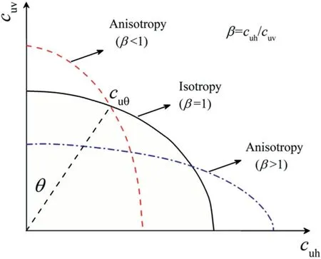
Fig.2.Schematic illustration of the variation of anisotropic undrained shear strength.
In this study,the results are reported in form of bearing capacity factor or dimensionless limit load factors for different combinations of horizontal, vertical and moment loads.The undrained shear strength factor, adhesion factor, degree of anisotropy, the inclination angle and eccentricity of the applied load with respect to the center of the pile in XZ plane are considered as the influencing factors denoted with cu/(γD),α,β,ω and e/D, respectively.
4.Method of analysis
4.1.Finite element limit analysis
The lower bound of the actual load in geomechanics can be reached by maximizing an objective function if any statically admissible stress field would exist, while satisfying a three-pronged set of requirements; the equilibrium conditions within the elements are to be met; the continuity constraints in stress discontinuities to be assured by applying the stress boundary conditions in prescribed nodes; and the state of stresses nowhere violating the yield criterion.
Fig.3 illustrates a typical finite element mesh discretization of the soil deposit into four-noded tetrahedral elements utilized in this study to evaluate the limit load of the pile embedded in an anisotropic clay deposit.To obtain more accurate solutions, finer meshes are used in the vicinity of the pile, and the mesh size increases by moving farther from the pile in horizontal direction.The extents of the domain are considered to be sufficiently large in all directions(with the radius of Rsoil=15D and height of Hsoil=2L)to eliminate boundary effects.These values were selected after conducting several trial-and-error analyses until the limit load of the pile seemed unwavering with further extension of the domain.Similar domain sizes have been reported by others.Hazzar et al.(2017), Keawsawasvong and Ukritchon (2020), and Graine et al.(2021) adopted 32D × 16D × (L + 6D), 10D × 5D × 1.4L, and 30D × 10D × (L + 5), for their pile bearing capacity studies,respectively.It can be seen that the assumed dimensions for the semi-infinite space of the current study (30D × 15D × 2L) are in close correspondence with those reported in the literature.By exploiting the advantage of the geometric symmetry, only half of the whole domain and pile is simulated to effectively reduce the computational time and efforts.The stress boundary conditions along the interfaces of soil and pile,the ground surface,and borders of the domain are shown in Fig.3.
Four-noded tetrahedral elements were used to discretize the soil domain in association with the 3D right-handed Cartesian coordinate system.Each node of the domain has six nodal unknownstress components including σxx, σyy, σzz, τxy, τyz, τzx, as shown in Fig.4a.In this study, the tensile stresses are taken to be positive.

Fig.3.FELB mesh discretization:(a)XY plane,(b)3D view in symmetry plane,and(c)3D view in other direction.
The state of stresses is considered to vary linearly within the elements.Therefore, the unknown nodal stress components constraint can be written as follows:
where Niis the linear shape function of the tetrahedral element.The equilibrium conditions within the tetrahedral elements are written as follows:
where γ is the soil unit weight.By substituting the stress variation equations within the element (Eqs.(1)-(3)) into the equilibrium equations (Eqs.(4)-(6)), the first set of nodal constraints are rendered as follows:
where[Aequil]is the multiplier matrix of equilibrium equations;and{bequil} and {σ} are the vectors of equilibrium equations and unknown nodal stresses, respectively.
Additional degrees of freedom in the lower bound theorem of limit analysis are introduced by defining the stress discontinuities.This is substantiated by having some nodes with the same coordinates but different states of stress (Fig.4b); it is deemed to improve the accuracy of the results by increasing the number of variables in mathematical optimization procedure (Shiau et al.,2011; Foroutan Kalourazi et al., 2019; Izadi et al., 2021; Izadi and Jamshidi Chenari, 2021, 2022).These extra degrees of freedom,although increasing the number of unknown nodal stress variables in the lower bound of limit analyses, increase the accuracy of the actual solution.This is imputable to the fact that by increasing the number of discontinuities, the states of stress can change more smoothly through the whole domain.In other words,higher stress gradients can more efficiently be adapted through the adoption ofsuch discontinuities.To satisfy the static admissibility of the stress field,the continuity constraints in all nodes in the shared planes of adjacent tetrahedral elements should be defined for normal and shear stresses,as shown in Fig.4c.For each pair of front points,the normal and shear stresses should be equaled:

Fig.4.FELB mesh discretization: (a) Nodal unknown stresses in tetrahedral element, (b) Typical illustration of numbering nodes in lower bound, (c) Stress discontinuity, and (d)Boundary condition.
where the normal and shear stresses in Eq.(8)can be found using stress transformation equations(Izadi and Jamshidi Chenari,2022),and the second set of nodal constraints is yielded as the following form:
where[Adisc]is the multiplier matrix of discontinuity equations,and{bdisc} is the vector of discontinuity equations.
For all the nodes, which are placed on the border of the mesh domain, as well as all the nodes, which are placed on the plane of symmetry, stress boundary conditions should be defined by enforcing their prescribed values.Fig.4d illustrates the allocation of prescribed values (tai, tbiand tciwhere i = 1-3) to the nodal boundary conditions.Fig.3 shows the stress boundary conditionsfor nodes placed on the borders and plane of symmetry.The third set of unknown nodal stress constraints, which are related to the boundary conditions, is written as
where[Abound]and{bbound}are the matrix and vector of boundary conditions, respectively.
In this study, two different cases are considered for soil-pile interface, including perfectly smooth and fully rough soil-pile interfaces.For the case of a perfectly smooth interface, the interface nodes cannot undergo either shear stresses or tensile stresses.In the fully rough soil pile interface, the interfacial nodes can sustain the full shear strength of the soil, i.e.α = τ/cu= 1, whereas the interfacial nodes have no resistance to the tensile forces (Graine et al., 2021; Izadi and Jamshidi Chenari, 2021, 2022).To simulate the adhesion impacts along the pile length, an inequity boundary condition of τ ≤αcushould be considered (Fig.3).
To let the soil separate from the back of the pile,the tension cutoff constraint is considered for all the nodes placed at the pile-soil interfaces.There are two major tension cut-off rules in the literature including constant and linear criteria, which can be seen in Fig.5.In the constant criterion, a separation takes place when the major principal tensile stress along the pile length exceeds the tensile strength of the soil.In the linear criterion,a separation arises if the major principal tensile stress exceeds the minimum of tensile strength and the value of tensile strength × (1 + lateral principal stress/compression strength).Note that the tensile and compression strengths are denoted by ftand fc, respectively.As the tensile strength of soil was assumed to be zero (Keawsawasvong and Ukritchon, 2020; Graine et al., 2021; Izadi and Jamshidi Chenari,2021), the separation of soil from the back of the pile and consequently the tension cut off behavior can be coded by preventing the state of stress in the direction of load application from being tensile,i.e.σx> 0 is forbidden (σx≤0 is allowable) (Izadi and Jamshidi Chenari, 2021, 2022).
The fourth set of nodal constraints is related to the yield criterion.The state of stresses in each node is enforced to be lower than the yield limit in which the quadratic constraints of the secondorder cone programming method (Qc) are satisfied, simultaneously.The von Mises yield function has the privilege of addressing the effect of intermediate principal stress over the Tresca criterion.Hence,the accuracy of calculating limit load in 3D stability problems by the von Mises yield function is expected to be higher than that of the Tresca yield function.To define the intended yield function into the standard form of the second-order cone programming method,mandatory conditions of auxiliary variables z1-z7and particular sign convention for normal stresses(due to the different sign conventions in FELB formulation and second-order cone programming method) should be applied:
where
By the combination of the above-mentioned 3D undrained yield criterion and mandatory condition of auxiliary variables z1-z7for conic quadratic constraint, the fourth set of nodal constraints of tetrahedral elements in the FELB theorem is generated as
where
where [Asocp] is the matrix of yield function in second-order cone programming method; [I] is the identity matrix; and {zsocp} and{bscop} are the vectors of auxiliary variables z1-z7and yield function equations,respectively.For a more detailed description of the 3D undrained yield criterion and mandatory condition of auxiliaryvariables z1-z7for conic quadratic constraint, readers are referred to Ukritchon and Keawsawasvong (2019).
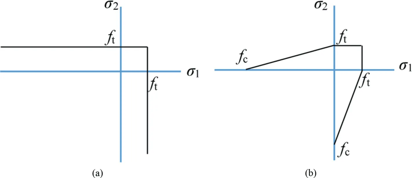
Fig.5.Tension cut-off rules: (a) Constant criterion, and (b) Linear criterion.
The effect of combined loading is examined in this study to account for the contributions of load eccentricity(e)and inclination(ω)in limit state of a pile subjected to the combined loadings.With a typical load combination exerted on the pile foundation, as depicted in Fig.1, the equilibrium equations for axial and lateral loads and moment along the soil-pile interfaces must be satisfied.The force equilibrium equations in the horizontal and vertical alignments are as follow:
where pi(i=x,y,z)is the stress in i direction and can be found as follows:
and n is the outward unit normal vector of the interfacial surfaces.Dividing Eq.(15) by Eq.(16) and manipulations lead to the following correlation:
It is evident that the horizontal and vertical bearing capacities are correlated with each other.The moment equilibrium equation along the soil-pile interface surfaces yields
where
where d is the distance of the interface nodes to the point of load application, and i = x, y, z.Therefore, the amount of the eccentrically inclined load(Q)is correlated to the lateral load H=Qsinω,the vertical load V=Qcosω,and M=Qecosω,respectively,and the fifth set of nodal constraint is defined in the matrix form as below:
where[Ainc],[Aecc]and{binc},{becc}are the matrices and vectors of inclined and eccentrically inclined loads,respectively.Note that Eq.(21a)is only used for the inclined load applied at the top center of the pile, while Eq.(21b) is composed of the multiplier of the simultaneous actions of the load inclination and eccentricity.
The objective function of FELB should be maximized subjected to five constraints set forth in the above-mentioned bundles of mathematical equations.Based on the aims of analysis, the lateral or vertical limit load of the pile can be selected as the objective function to find the maximum lower bound solution of either lateral or vertical loads.By maximizing the objective function, the values of other load components can be found through their correlations:
where[Aobj]is the matrix of objective function related to the area of the elements and H or V is the lateral or vertical limit load of the pile.By assembling the constraint equations and the objective function throughout the domain and deploying MOSEK as a primaldual interior-point algorithm(Andersen et al.,2003),the limit load of the pile under combined loading can be found in the following form:
subjected to
4.2.Incorporating the anisotropy by an iterative procedure
The above-mentioned formulations are resorted to calculate the undrained limit load of the pile under isotropic conditions.For capturing the effect of anisotropy on the limit load of pile, an iterative procedure is utilized.Indeed,the results of the current study are based on the von Mises yield function with an iterative procedure to address the effects of the anisotropy and directionality of the undrained shear strength of the soil.In the first round of analysis, the limit load of the pile embedded in an isotropic soil is calculated subjected to the adopted equality and inequality constraints.The states of stresses in all nodes are written in matrix form.Subsequently, the major principal stresses and their directions can be found by calculating the eigenvalues of the stress matrices.At this step,the undrained shear strength of the soil in all of the nodes is updated with respect to the anisotropy degree β,direction of the major principal stresses relative to the vertical axis θ, and the following linear, sine and cosine functions, which are widely used for the undrained shear strength anisotropy based on the experimental studies of Cassagrande and Carillo (1944), Lo(1965), Davis and Christian (1971), Siddiquee et al.(2001), and Gao and Zhao (2012):
According to the transverse isotropy, the undrained shear strength parameters of the soil in π/2-π are equal to the intended values in 0-π/2.
Again, the nodal constraints are defined and the limit load is calculated based on the updated values of shear strength.Then the convergence criterion is checked for successive iterations.The iteration-based update procedure ceases when the convergence criterion is satisfied for successive solutions as follows:
where Prand Pr-1are the successive solutions in the iterations of r and r-1,respectively,with the allowable convergence tolerance of ε = 1%.The details of the iterative computational procedure employed in this study to calculate the limit load of the pile embedded in cross-anisotropic soil under combined loading are illustrated in a flowchart in Fig.6.
5.Verification
Before conducting parametric study on the limit load of the pile embedded in the cross-anisotropic soil deposit under combined loading, the aptitude of the proposed iterative 3D finite element limit analysis method is verified against three different cases.To this end,lower bound theorem of limit analysis in association with the second-order cone programming method is deployed.The first case corresponds to the calculation of the undrained bearing capacity ratio of a laterally loaded pile; the second case verifies the end-bearing capacity of a shallow circular pile embedded in crossanisotropic soils;and the third one belongs to the limit load of a pile embedded in isotropic soil subjected to the inclined load.
5.1.Case 1: Undrained lateral limit load of a pile under purely horizontal load
Table 1 shows the variation of the undrained lateral limit load of a pile placed in cohesive soil with different embedment length ratios L/D,different soil unit weight factors of n=γL/cu,and fully rough soil-pile interface α = 1.The results of the current study were compared with those of Broms (1964), Meyerhof et al.(1981), Murff and Hamilton (1993), Georgiadis et al.(2013), Yu et al.(2015), and Keawsawasvong and Ukritchon (2020).It can be seen that the results of these studies and those of the current study are in general agreements.However,the deviations could be attributed to the inherent differences between the methods of analysis adopted in each study,their underlying assumptions,and the optimization approach invoked in each method.To be morespecific, the studies of Murff and Hamilton (1993) and Yu et al.(2015) are based on the upper bound (UB) limit analysis method, which explains the notable deviations between the results.For the rest of the cases, especially for Keawsawasvong and Ukritchon (2020), which is based on finite element method(FEM)-based strain-strain analyses, good level of correspondence is observed with the current study.It is also worth mentioning that some of the cases, Georgiadis et al.(2013) for example, are predicated on the assumption of plain strain geometric idealization, which could introduce another source of deviation between the results.

Table 1Validation of the lateral limit load of a pile under purely horizontal load.
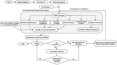
Fig.6.Flowchart for the iterative update of the FELB limit analysis method used for cross-anisotropic soils.
5.2.Case 2: Undrained end bearing capacity of a pile in crossanisotropic soil
To validate the iterative procedure of the proposed formulations and in the scarcity of any reported literature on the limit load of piles under combined loading, the results of this study are compared with those of Ukritchon and Keawsawasvong (2020) on the ground of end-bearing capacity of a shallow circular pile embedded in a cross-anisotropic soil deposit.Based on the experimental investigations,they extended the von Mises yield function to the case of anisotropic condition and proposed an anisotropic undrained yield criterion, which is called the UK yield function.Fig.7 demonstrates the variation of the undrained end-bearing capacity factor based on the iterative 3D FELB limit analyses.The iteration-based isotropic von Mises yield criterion of this study is validated against the modified von Mises yield function (UK yield function) of Ukritchon and Keawsawasvong (2020) under axisymmetric geometric idealization.
Comparative study corroborates the consistency of the results in the estimation of anisotropic undrained end-bearing capacity;hence,bearing witness to the efficacy of the iterative procedure and different anisotropy functions adopted herewith.The deviation between the two studies remains always less than 15%, which is deemed sensible due to the inherent differences between the formulations and assumptions of the iterative isotropic 3D lower bound theorem of this study and the 2D anisotropic UK yield criterion adopted by Ukritchon and Keawsawasvong (2020).
But unfortunately, in spite of all her care, he grew so vain and frivolous10 that he quitted his peaceful country life in disgust, and rushed eagerly after all the foolish gaieties of the neighbouring town, where his handsome face and charming manners speedily made him popular
5.3.Case 3: Undrained normalized limit load of a pile under inclined loadings
Fig.8 demonstrates the variation of the normalized limit load of a smooth pile for the case of embedment length ratio of L/D=6 in isotropic soil with the undrained shear strength of cu=50 kPa.It isworth mentioning that the limit loads of the pile under purely horizontal and vertical loads are denoted with H0and V0, respectively,and the superscript‘+’above V0means that the compressive vertical load was considered as positive, i.e.V+0is compressive vertical load.Ten different inclination angles were considered for the applied inclined load.As the limit load of the pile with an inclination angle of ω is equal to the corresponding value for its double angle -ω, the normalized limit load curves are symmetric with respect to the vertical axis.Note that for an inclination angle lower than 45°, the objective function is the vertical limit load,while for ω ≥45°,the lateral limit load was chosen as the objective function.
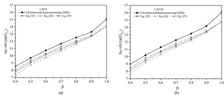
Fig.7.Verification of the results of the current study for end bearing capacity factor (Nc) of a shallow pile in anisotropic soils against Ukritchon and Keawsawasvong (2020).

Fig.8.Comparison of the results of the current study with the results of normalized inclined limit load reported in the literature (α = 0, L/D = 6, cu = 50 kPa).
Meyerhof and Yalcin (1984) conducted load tests on smooth piles fully embedded in cohesive soils and measured the limit load of piles subjected to the inclined loading and proposed a semiempirical elliptic failure envelope based on different combinations of the loading components.Eq.(29) shows their suggested formulation for calculating the normalized limit load:
Graine et al.(2021)calculated the lateral limit load of the pile in the presence of a vertical loading component.Different levels of vertical loading component were chosen so as to reflect a portion of the maximum vertical limit load of the pile under study.As shown in Fig.8,the results of this study have acceptable consistency with those reported in the literature.
6.Results and discussion
In this section, the limit load of a pile embedded in a crossanisotropic soil deposit is reported, by adopting a combined loading scheme,in both V-H and V-H-M spaces,with the latter to incorporate eccentricity as well.A parametric study is conducted with dimensionless parameters according to Table 2.
It is widely reported by many researchers that the soil unit weight has a negligible impact on the bearing capacity of the pile embedded in cohesive soils(Keawsawasvong and Ukritchon,2020;Graine et al., 2021).The validation results of the current study presented in Table 1 cross-confirmed this fact.Hence,the soil unit weight was kept constant through all the analyses(γ=20 kN/m3).Based on the computational procedure of bound theorems of limit analysis, the accommodation of pile rigidity is considered to be a limitation of this method.However, it is worth noting that short piles predominantly behave like a rigid pile, whereas long piles mostly act as flexible elements.Therefore, the limit load of rigid piles can be found by finite element limit analysis, as long as they could be assumed rigid.Hence, to obtain more accurate and rigorous solutions, the embedment length to diameter ratio of the pile is limited to L/D = 10.

Table 2Dimensionless input parameters of the current study.
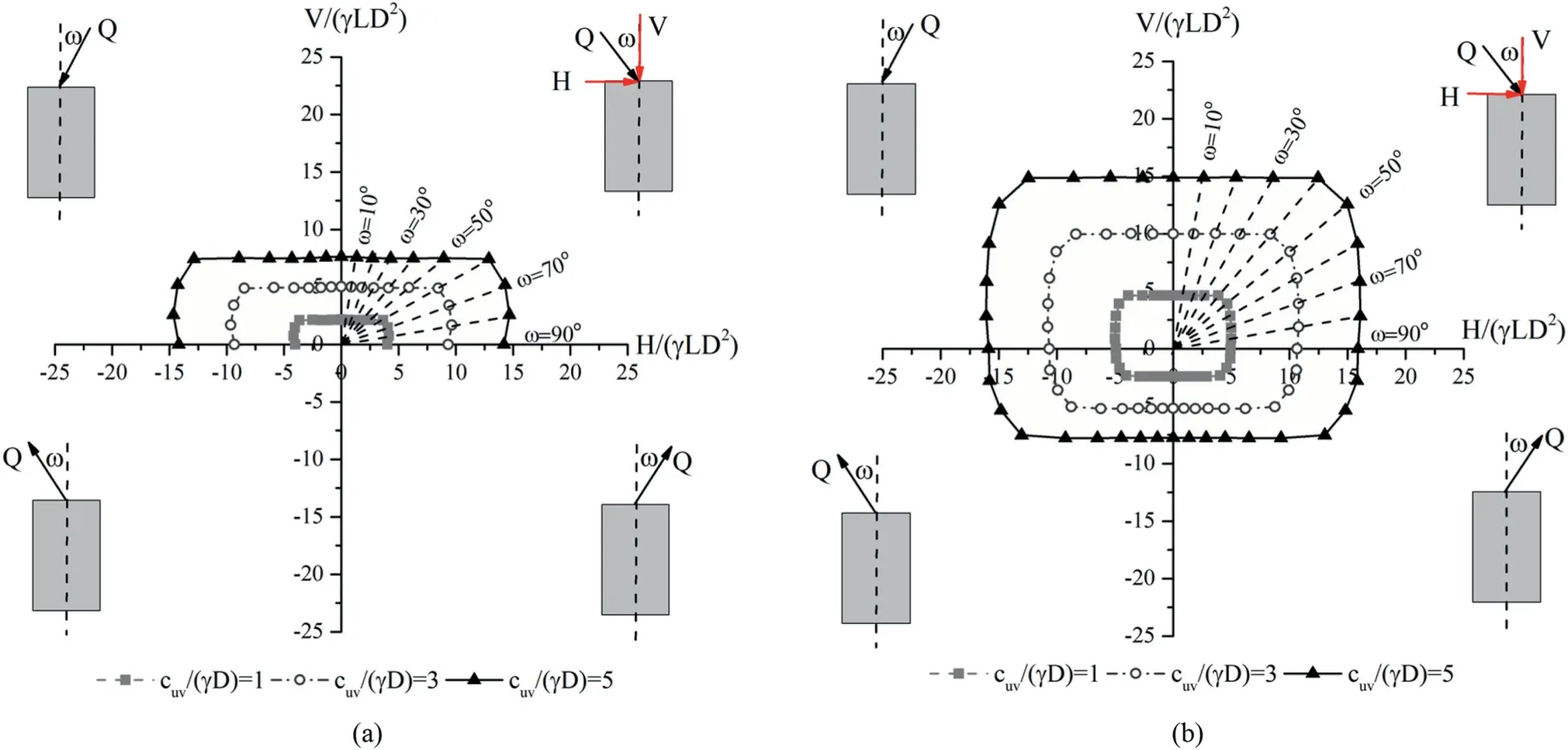
Fig.9.Limit load curves of the pile versus different undrained shear strengths of soil: (a) Perfectly smooth and (b) Fully rough interfaces (L/D = 10, β = 1).
6.1.Limit load of pile in V-H space
In this section,the limit loads of a short rigid pile under inclined loading (e = 0, M = 0) for both perfectly smooth (α = 0) and fully rough (α = 1) interfaces are reported.For this purpose, it was assumed the load inclination angle (ω) to range from 0°to 360°,with 10°steps;the inclined load is applied on the center of the pile head.A parametric study is conducted to capture the effects of the undrained shear strength of the soil, and the mechanical anisotropy.Furthermore,the uplift limit load of the pile is also studied for a fully rough interface.
6.1.1.Effect of undrained shear strength on the limit load of pile
The inclined limit load of the pile embedded in soil with different dimensionless undrained shear strengths is depicted in Fig.9 for both perfectly smooth (α = 0) and fully rough (α = 1)interfaces.Only the highest embedment length ratio of L/D=10 is illustrated as similar trends can be observed for all other embedment length ratios.Due to the symmetry of the problem with respect to the vertical axis,only half of the load paths are needed to profile the trajectories in the V-H space(i.e.0°-90°for smooth and 0°-180°for rough interfaces).Therefore,by covering solely the first and fourth quadrants,the whole failure envelope can be drawn for different cases.As expected,the limit load of the pile increases with increases in the undrained shear strength and adhesion factor.It is also evident from Fig.9 that,for piles with fully rough interface,the shear strength of the surrounding soil continues to be mobilized even during the pull-out action.Furthermore, it can be easily deduced from Fig.9 that the compressive limit loads of the pile are higher than the tensile part.This observation arises from the fact that in the compressive cases,the shaft resistance and end-bearing capacity count together towards the overall limit load.On the contrary, the effect of end-bearing capacity is eliminated for pullout loading condition.
It can be seen from Fig.9 that a sudden drop in vertical limit load is expected when the inclination angle(ω)exceeds 60°and 50°for perfectly smooth and fully rough interfaces,respectively.However,for lower inclination angles, the lateral limit loads of the pile start decreasing abruptly.This is the core finding of this study, which is ascribed to the fact that deep foundations, due to their slender geometry, mobilize the soil shear strength either laterally or vertically.Therefore, by increasing the load inclination, only the maximum lateral limit load mobilizes; the vertical loading component, in this case, does not contribute significantly to the lateral limit load of the pile.However, it is confirmed that in subhorizontal loading condition (ω = 80°for smooth and ω = 70°for rough interfaces),the maximum combined horizontal limit load is slightly higher than the sole lateral limit load.
On the other hand, for lower inclination angles, it is only the axial bearing capacity of the pile,which is triggered due to the shaft and tip resistances.Exerting additional horizontal loading, in this case, does not contribute more to the axial limit load.Indeed, the augmented lateral stresses are not translated into additional shaft resistance in undrained loading condition.Again, the highest calculated vertical limit loads are obtained when the inclination angle is ω = 0°.However, in the absence of any evidence to the contrary,it is expected the failure envelopes to undergo changes in drained loading condition, due to the importance of both the adhesion and normal stress in shaft resistance mobilization.
6.1.2.Effect of mechanical anisotropy on the limit load of pile
The expansion of the safe loads of piles embedded in an anisotropic soil deposit is depicted in Figs.10 and 11 as functions of the anisotropy degree and principal stress rotation for smooth and rough soil-pile interfaces, respectively.Note that the numericalfinite element limit solutions,plotted in Figs.10 and 11,are related to the pile embedment length ratio of L/D=10 and constant vertical undrained shear strength ratio of cuv/(γD)=5.Similar observation was made for all other embedment length (L/D <10), and undrained shear strength ratios adopted.It is noteworthy that in the anisotropy degree equation (β = cuh/cuv), the value of undrained shear strength in the vertical direction is kept constant and used for the sake of presentation of dimensionless parameters, while the undrained shear strength in the horizontal direction is selected as the variable parameter in the anisotropy degree equations.
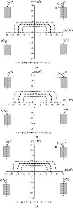
Fig.10.Failure curves in the V-H space for different anisotropy degrees, smooth interface and different anisotropy functions: (a) Linear function (Eq.(25)), (b) Sine function (Eq.(26)), and (c) Cosine function (Eq.(27)).
It can be seen from Figs.10 and 11 that the limit load of the pile increases with increases in anisotropy degree and adhesion factor.As expected, an increase of the anisotropy degree results in an increase of the soil resistance acting along the border of piles and consequently brings about a rise of the limit load of the pile.In other words, by increasing the anisotropy ratio, the undrained shear strength of the soil in the horizontal direction increases,and consequently the lateral limit earth pressures augment and reach the ultimate passive lateral resistance along the pile length (i.e.passive condition is more prone to occur).It is also noted that the effect of mechanical anisotropy is more pronounced in the lateral limit load of the pile in comparison to the axial limit load.This effect has embodied as more elongated (anisotropic) failure envelopes in comparison to their isotropic counterparts.
Apropos of the anisotropy function,an observation can be made by comparing different curves of Fig.12;for soils with an anisotropy degree lower than 1,the sine anisotropy equation suggests a more conservative lateral limit load,while the cosine anisotropy equation renders higher values.For the cases of anisotropy degree higher than 1,the sine anisotropy equation yields higher lateral limit load estimations and the linear anisotropy equation renders the lowest values.
6.2.Limit load of pile in V-H-M space
In this section, the limit load curves of the short rigid pile embedded in cross-anisotropic soil deposit under eccentrically inclined loads are calculated for both perfectly smooth and fully rough interfaces.To this end,it was assumed that the inclined load with inclination angle ω ranging from 0°to 360°and interval step of 10°is being applied with an eccentricity ratio (e/D) ranging from -1/2 to 1/2 and the interval step of 1/6 (Fig.1).A series of parametric analyses is conducted to address the effects of eccentricity,anisotropy degree,and rotation of principal stress direction.As a non-limiting example,the results of the short rigid pile under general loading condition are reported for embedment length ratio of L/D=10 and constant vertical undrained shear strength ratio of cuv/(γD) = 5.
6.2.1.Effect of eccentricity on the limit load of pile
The FELB solutions of all different load paths of the pile under general loading conditions are presented as 3D failure surfaces in Fig.13 for smooth and rough interfaces.For the sake of better illustration, the variations of axial, lateral, total bearing capacity factors as well as over-turning moment factor are depicted in Figs.14 and 15 in the form of radar charts for smooth and rough interfaces, respectively.
Due to the symmetry of the problem with respect to the vertical axis, the lateral and vertical bearing capacity curves for negative eccentricity ratio are quite similar to the corresponding values for positive eccentricity ratio.Analogous to the case of the pile under inclined loading, no pullout capacity was observed for the smooth soil-pile interface,while the utilization of shear strengths of the soil even during the pull-out action results in pull-out capacity for the fully rough interface.By comparing different parts of Figs.13-15,itcan be seen that the compressive limit loads are relatively 1.7 times the uplift limit loads.The over-turning moments for negative and positive eccentricity ratios have almost the same absolute values.It can be also seen from Figs.13-15 that the lateral, axial and total limit loads of pile decrease with an increase of eccentricity ratio,while the sustainable bending moment increases.
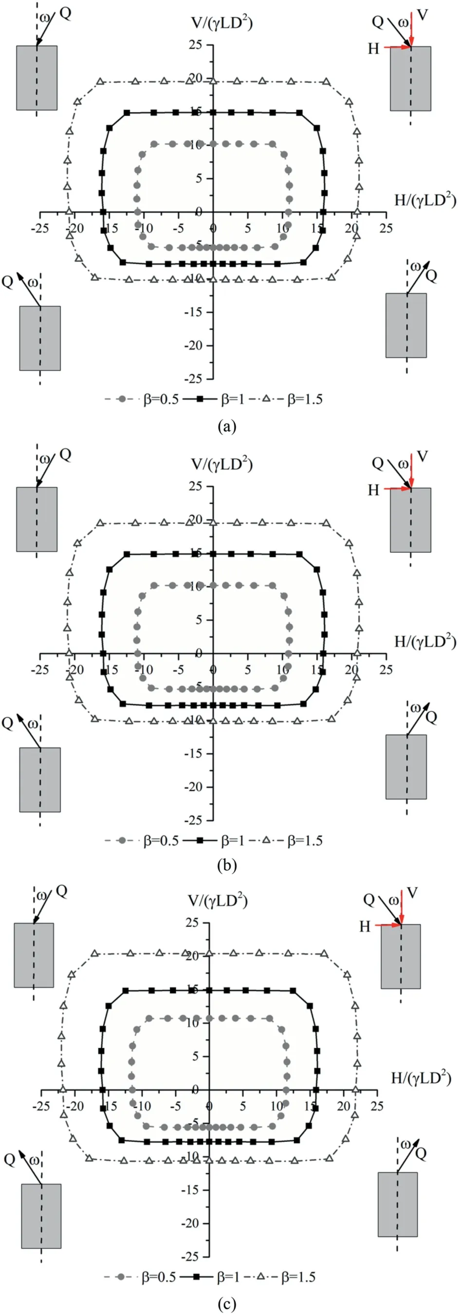
Fig.11.Failure curves in V-H space for different anisotropy degrees, rough interface and different anisotropy functions:(a)Linear function(Eq.(25)),(b)Sine function(Eq.(26)), and (c) Cosine function (Eq.(27)).
Another observation from Figs.13-15 is that the adhesion factor plays a vital role in both vertical limit load and bending moment capacities.For instance, the vertical and bending moment capacities of the smooth pile are about 49%and 55%of the corresponding values of the rough pile while the differences between the results of lateral bearing capacity in smooth and rough interfaces are less pronounced.
In order to shed more light on the issue of load eccentricity and its contribution to different limit load bearing capacity components, more observations are extracted from the provided illustrations (Figs.13-15).It is noted that in the absence of load inclination,increasing the load eccentricity will bring about a slight reduction in the vertical limit load.The moment load is the joint contribution of two counteracting contributors, i.e.the eccentric vertical load component and the eccentricity itself.An increase in the eccentricity, while increasing the moment load directly, will bring about a slight reduction in the vertical limit load.However,the overall contribution of the load eccentricity is to increase the limit moment loading borne by the pile.
6.2.2.Effect of mechanical anisotropy on the limit load of pile
The 3D safe load curves of the pile under general loading conditionsinthe V-H-M space asfunctions of different anisotropy degrees and eccentricity ratios are presented in Fig.16 for smooth and roughinterfaces.Note that the numerical finite element limit solution plotted in Fig.16 is related to the pile embedment length ratio of L/D = 10, constant vertical dimensionless undrained shear strength ratioofcuv/(γD)=5,and only the sineanisotropyequation asthe most sensitivefunctionwhich wascorroboratedinthe previoussection.For the sake of brevity and ease of understanding the simultaneous impacts of anisotropy and eccentrically inclined load,the limit loads of pile in the V-H and H-M spaces are depicted in Figs.17 and 18 for all different anisotropy degrees,anisotropy functions and only the positive eccentricity ratios for smooth and rough soil-pile interface,respectively.Due to the symmetry,the limit load curves in the V-H space are almost the same,while the corresponding curves in the HM space have almost the same absolute values.

Fig.12.Failure envelopes in V-H space for different anisotropy degrees and functions:(a)Smooth interface,β=0.5;(b)Smooth interface,β=1.5;(c)Rough interface,β=0.5;and(d) Rough interface, β = 1.5.

Fig.13.3D failure curves of a short rigid pile under general loading condition: (a) Smooth interface and (b) Rough interface.
By comparing different parts of Figs.16-18,it can be concluded that the lateral and vertical limit loads of pile increase with an increase in the anisotropy degree, adhesion factor, and reduction of eccentricity ratio.However,the effect of anisotropy in the variation of the lateral limit load of pile is more pronounced than the vertical and bending limit loads,which is due to the fact that an alteration of anisotropy degree directly changes the lateral soil resistance acting along the pile length.On the other hand, the interface properties have more significant effects on the vertical and bending limit loads in comparison to the lateral limit load component.
Furthermore,it can be seen from Figs.16-18 that for soils with an anisotropy degree lower than 1, the sine anisotropy equation suggests a more conservative lateral limit load, while the cosine anisotropy equation renders higher values; for the cases of anisotropy degree higher than 1,the sine anisotropy equation yields higher lateral limit load estimations and the linear anisotropy equation leads to the lowest values.
7.Conclusions
In most practical cases,piles are rarely subjected to purely axial,lateral, or bending moment loads individually.Therefore, consideration of different combinations of axial,lateral,as well as bending moment loads and their interactive effects is indispensable.Furthermore, most natural soil deposits exhibit some degrees of anisotropy in their mechanical properties including shear strength and stiffness and the effects of anisotropy on geotechnical stability problems have been paid less attention.To shed more light on the problem of deep foundation embedded in anisotropic soils under general loading conditions, a set of iterative-based 3D FELB analyses associated with second-order conic programming have been conducted.To address the effect of anisotropy, three different anisotropy functions were exploited.Furthermore, the limit load was calculated for different possible combinations of contributing components and the results are calculated using an iterative-based procedure sought to incorporate the directionality of shear strength parameter(s).A parametric study was also conducted to capture the impacts of different influencing factors including the undrained shear strength of soil, adhesion factor, anisotropy degree, rotation of major principal stress direction, load inclination, and eccentricity.The following conclusions were made through comparison of different outcomes:
(1) The general takeaway from this research is that the limit load of pile increases with an increase of undrained shear strength of the soil, adhesion factor, and anisotropy degree for both smooth and rough interfaces.
(2) By exceeding the load inclination angle from 60°to 50°for perfectly smooth and fully rough interfaces,respectively,the vertical limit load of the pile significantly diminishes.In such cases, the lateral load bearing capacity of the pile governs and the response of the pile is more similar to the pile under pure lateral loading.However, once the load inclination angle falls below 60°and 50°for perfectly smooth and fully rough interfaces, respectively, the lateral limit load of pile decreases abruptly and the main response of the pile becomes axial.
(3) By increasing the anisotropy degree, the lateral soil resistance acting along the pile length increases accordingly,and the lateral earth pressures augment and reach the ultimate passive lateral resistance accordingly.Therefore, the lateral bearing capacity increased more pronouncedly in comparison to the vertical limit load component.
(4) For soils with an anisotropy degree lower than 1,the use of a sine anisotropy function leads to err on the side of caution,while the cosine anisotropy equation renders the largest predictions.On the other hand, for the cases of anisotropy
degree higher than 1, the sine anisotropy degree function yields higher lateral limit load estimations and the linear anisotropy degree function leads to lower values.
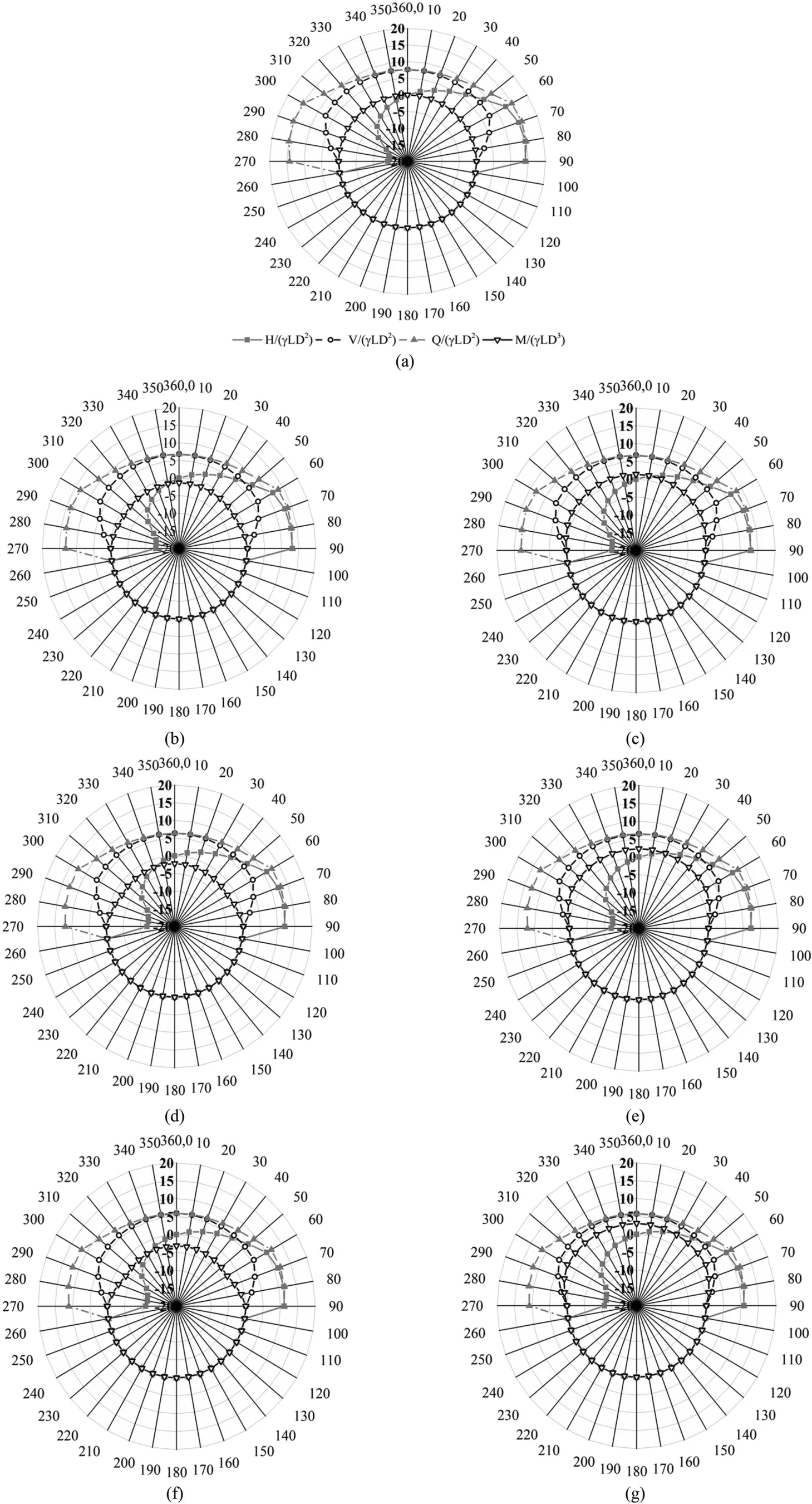
Fig.14.Expansion of limit eccentrically inclined load curves for the smooth soil-pile interface:(a)e/D=0,(b)e/D=-1/6,(c)e/D=1/6,(d)e/D=-1/3,(e)e/D=1/3,(f)e/D=-1/2,and (g) e/D = 1/2.The numbers around the circle are in degree.
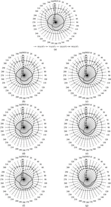
Fig.15.Expansion of limit eccentrically inclined load curves for the rough soil-pile interface:(a)e/D=0,(b)e/D=-1/6,(c)e/D=1/6,(d)e/D=-1/3,(e)e/D=1/3,(f)e/D=-1/2,and (g) e/D = 1/2.The numbers around the circle are in degree.

Fig.16.3D failure curves of short rigid piles under general loading condition:(a)Smooth,β=0.5;(b)Smooth,β=1;(c)Smooth,β=1.5;(d)Rough,β=0.5;(e)Rough,β=1;and(f)Rough, β = 1.5.
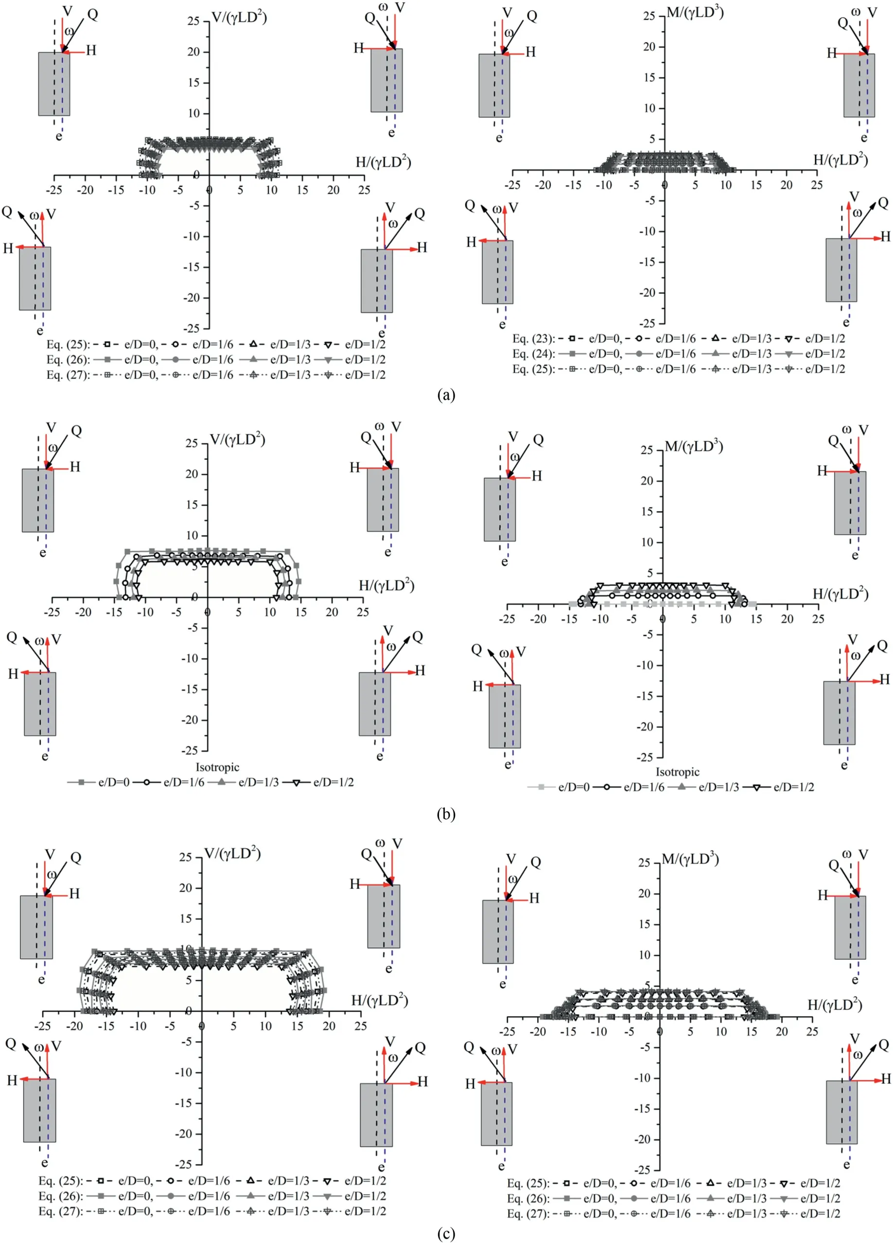
Fig.17.Failure curves in V-H and M-H spaces for different anisotropy degrees and eccentricity ratios for smooth interface: (a) β = 0.5, (b) β = 1, and (c) β = 1.5.

Fig.18.Failure curves in V-H and M-H spaces for different anisotropy degrees and eccentricity ratios for rough interface: (a) β = 0.5, (b) β = 1, and (c) β = 1.5.
(5) Comparative studies showed that the vertical limit load of pile would exhibit slight decrease with an increase of the eccentricity, while the sustainable bending moment augments accordingly.
Declaration of competing interest
The authors declare that they have no known competing financial interests or personal relationships that could have appeared to influence the work reported in this paper.
 Journal of Rock Mechanics and Geotechnical Engineering2023年3期
- Journal of Rock Mechanics and Geotechnical Engineering的其它文章
- Calibration of an elastoplastic model of sand liquefaction using the swarm intelligence with a multi-objective function
- Predicting and validating the load-settlement behavior of large-scale geosynthetic-reinforced soil abutments using hybrid intelligent modeling
- Effects of biochar-amended alkali-activated slag on the stabilization of coral sand in coastal areas
- Development of mathematically motivated hybrid soft computing models for improved predictions of ultimate bearing capacity of shallow foundations
- Long-term decay of the water pressure in the osmotic tensiometer
- Numerical simulation of fatigue crack propagation in heterogeneous geomaterials under varied loads using displacement discontinuity method
