Numerical simulation of fatigue crack propagation in heterogeneous geomaterials under varied loads using displacement discontinuity method
Rezvn Alizdeh, Mohmmd Ftehi Mrji,*, Aolfzl Adollhipour,Mehdi Pourghsemi Sgnd
a Department of Mining and Metallurgical Engineering, Faculty of Engineering, Yazd University, Yazd, Iran
b School of Mining Engineering, College of Engineering, University of Tehran, Tehran, Iran
Keywords:Fatigue life Crack coalescence Interface Incorporation technique Variable amplitude loading
ABSTRACT Heterogeneous brittle geomaterials are highly susceptible to cyclic loads.They contain inherent flaws and cracks that grow under fatigue loads and lead to failure.This study presents a numerical model for analyzing fatigue in these materials based on the two-dimensional (2D) boundary element method and linear elastic fracture mechanics.The process is formulated by coupling the displacement discontinuity method with the incorporation technique of dissimilar regions and the governing equations of fatigue.The heterogeneous media are assumed to consist of materials with different properties, and the interfaces are assumed to be completely bonded.In addition,the domains include multiple cracks exposed to constant and variable amplitude cyclic loads.The stress intensity factor is a crucial parameter in fatigue analysis,which is determined using the displacement field around crack tips.An incremental crack growth scheme is applied to calculating the fatigue life.The growth rate values are employed to estimate the length of crack extension when there are multiple cracks.The interaction between cracks is considered,which also includes the coalescence phenomenon.Finally,various structures under different cyclic loads are examined to evaluate the accuracy of this method.The results demonstrate the efficiency of the proposed approach in modeling fatigue crack growth and life estimation.The behavior of life curves for the heterogeneous domain was as expected.These curves illustrate the breakpoints caused by utilizing discrete incremental life equations.At these points, the trend of the curves changed with the material properties and fatigue characteristics of the new material around the crack tips.
1.Introduction
Developing numerical methods for solving complex geomechanical problems through realistic modeling has received scholars’ attention over the past two decades.In particular,research on modeling fatigue under cyclic loads provides promising contributions.Brittle materials undergo fatigue failure at stresses below their ultimate strength under cyclic loads.These materials,such as rock and concrete,contain inherent flaws and cracks.These cracks grow and lead to failure due to fatigue.Predicting the crack growth path and fatigue life is essential to prevent catastrophic events in these materials.When fatigue crack growth occurs in complicated domains, these predictions encounter many challenges.Therefore, it is crucial to develop fatigue growth modeling for brittle, heterogeneous regions through numerical methods since most real-life media are complex.Brittle materials, such as rocks, are inherently cracked heterogeneous media.These heterogeneous regions can also be created artificially,as with the contact of rock and concrete structures.
Experimental methods have been the pioneering approach for developing numerical methods.Accordingly, numerous experimental and analytical studies have been conducted to examine the fatigue process of heterogeneous media.Many experimental investigations studied fatigue crack behavior near the interface,which is considered to be either perpendicular to the cracked plane(Suresh et al.,1992; Jiang et al., 2003) or inclined (Kolednik et al.,2010).Most studies reduce the complicated heterogeneous structures to bi-material systems(Slowik et al.,1998;Shah et al.,2014).Milan and Bowen(2003)and Sugimura et al.(1995)examined the influence of relative mechanical properties adjacent to the interface.They also evaluated the change of crack propagation for softto-hard or hard-to-soft material transitions.The behavioral characteristics of the interface are also influential factors in crack extension.For instance,thin,compliant and soft interlayers reduce the crack driving force and lead to the retardation of fatigue crack growth(Kolednik et al.,2016;Sistaninia et al.,2018).Despite all the advantages, experimental methods are available only for a limited group of geometric combinations and boundary conditions;therefore,it is essential to use numerical methods for fatigue crack growth modeling in heterogeneous domains.The finite element method (FEM) has been on the front line of numerical simulation techniques for several decades and has been successfully used to model fatigue crack growth in heterogeneous domains (Kolednik et al., 2009; Moslemian et al., 2011; Alshoaibi and Fageehi, 2021).To use FEM for the iterative crack growth scheme, extremely fine meshing is required around crack tips to calculate the high-stress gradient; moreover, each increment of the analysis requires remeshing.Moës et al.(1999) investigated this challenge and introduced the extended FEM (XFEM) that exploits local enrichment functions to model cracks independently of the finite element meshes.Pathak et al.(2013) extended fatigue crack growth in an inhomogeneous structure using XFEM.
In recent years, meshless methods have also been applied to developing numerical models of fatigue procedures in heterogeneous materials.The element-free Galerkin method (EFGM)(Belytschko et al.,1994), free mesh method (Yagawa and Yamada,1996), meshless local Petrov-Galerkin (Lin and Atluri, 2001), and reproducing kernel particle method (Liu et al.,1997) are meshless methods for fatigue and crack analysis.The EFGM is a robust method to solve fracture mechanic problems.Muthu et al.(2016)used it to study crack growth in heterogeneous structures.Moreover,a new version of EFGM has been introduced to simulate crack propagation under mechanical and thermo-elastic cyclic loads(Pathak et al., 2014).Sladek et al.(2005) employed a meshless method based on the Petrov-Galerkin approach to model crack propagation in anisotropic heterogeneous materials.
The boundary element method (BEM) has become wellrecognized for modeling fracture, especially for crack growth(Aliabadi and Rooke, 1991).BEM is more efficient than other numerical methods where stress changes rapidly.In this method,only the boundaries of the structures and cracks need to be discretized.Consequently,the dimension of the problem is decreased,which is more economical and remarkably reduces the data required for analysis.BEM-based techniques provide a more accurate description of singular fields of crack tips, leading to a precise estimate of the stress intensity factor (SIF), which is significant in solving problems with fatigue crack phenomena.The fatigue crack growth rate has been introduced by a power-law function of the SIF;thus,decreasing errors in evaluating the SIF leads to more reliable life estimates.Ingraffea et al.(1983)pioneered the automatic modeling of crack propagation under mixed-mode conditions.
Doblare et al.(1990) used the quarter-point elements in the multi-region method to simulate crack propagation in materials.BEM was also developed to calculate SIFs for cracks near the interfaces of dissimilar materials(Ryoji and Sang-Bong,1989).Alaimo et al.(2013) employed BEM coupled with the multi-domain technique to study the fracture behavior of heterogeneous structures.Yu et al.(2015) extended BEM to evaluate the fatigue crack growth of inhomogeneous structures.Portela et al.(1993)and Mi and Aliabadi(1994) developed the dual BEM (DBEM) for two-dimensional (2D)and three-dimensional (3D) crack propagation problems, respectively.An advantage of DBEM is that the crack extension can be created simply by new elements.DBEM has been extended to simulate 3D cracks in layered and graded areas(Xiao et al.,2019).In addition to DBEM, the indirect BEM has been developed with the principle of superposition.It includes the fictitious load method(FLM) and displacement discontinuity method (DDM).Due to the characteristics of the displacement discontinuity parameters of the crack surface,DDM is suitable for solving crack problems.Indeed,it expresses the stresses and displacements of a particular point through the displacement discontinuity of defined elements.Crouch and Starfield (1983) proposed the 2D DDM to analyze crack problems of homogeneous materials.Shen et al.(2014) also formulated the 2D DDM for different homogeneous materials in multiple regions.The DDM with constant elements has been used to solve many problems in fracture mechanics(Ling and Suaris,1991;Scavia,1991).Yan (2007) modeled fatigue crack growth in homogeneous materials using constant ordinary and crack tip elements.This method has been extended using linear and quadratic elements for a more reliable predicting of stresses and displacements at the field points adjacent to the boundaries(Peirce,2010;Fatehi Marji,2015a).The DDM was coupled with other methods to solve elastodynamics,hydro-mechanical and thermo-hydro-mechanical problems in geomechanics (Fan et al., 2011; Abdollahipour et al., 2013;Abdollahipour, 2015; Lak et al., 2019a,b; Abdollahipour and Fatehi Marji, 2020).The higher-order DDM was modified to solve many problems in rock fracture mechanics, hydraulic fracturing, and fatigue crack growth (Fatehi Marji et al., 2007; Fatehi Marji, 2015b;Abdollahipour et al.,2016;Alizadeh et al.,2021).The DDM was also extended for modeling complicated heterogeneous materials.The initial effort for this purpose was an extension of the DDM principle to model various heterogeneous mining problems (Diering, 1980).Shou and Napier (1999) applied the 2D DDM with a novel superposition scheme to study multi-layered elastic media.Also, a 3D formulation of the method was developed by Xiao and Yue (2011).Siebrits and Peirce (2002) introduced a planar 3D DDM algorithm based on a fixed-mesh approach to model fracture propagation in multi-layer materials.Long and Xu (2016) combined the direct boundary integral method and DDM for crack propagation in heterogeneous elastic media.The extended DDM was developed to analyze interface cracks of arbitrary shapes in transversely bimaterials (Zhao et al., 2017).Fan et al.(2019) employed a new general solution with Fourier transforms to analyze interface cracks in 2D quasicrystal materials.
The present study proposes a new version of DDM to model the simultaneous growth of several fatigue cracks in heterogeneous brittle media.The DDM and the incorporation technique(Crouch and Starfield,1983) of homogeneous and isotropic sub-regions are used to develop a heterogeneous system.The DDM analysis, in combination with Walker and Paris laws as the governing equation of fatigue, is applied to modeling the incremental propagation and life estimations.Finally, three numerical examples evaluated the proposed method.The remaining parts of this paper are arranged as follows.In Section 2,the principle of the DDM and its development based on the incorporation technique are explained.The fatigue-DDM procedure is described in Section 3.The simultaneous growth and coalescence of cracks in heterogeneous material are examined in Section 4.Section 5 describes the process of fatigue cracks growth modeling via the given algorithm.Numerical examples to validate the proposed approach are presented in Section 6.Finally, Section 7 discusses the main contributions and concluding remarks.
2.Incorporation technique of dissimilar materials with DDM
The BEM is a semi-analytical technique.Analytical solutions are estimated for singular problems, which approximately meet the boundary conditions of the problem.Numerical procedures are developed through these solutions.The DDM is also an indirect BEM.It is widely used to solve fracture problems based on linear elastic fracture mechanics (LEFM).The DDM develops a discrete approximation of a continuous distribution of displacement discontinuity(DD)along a segment.Based on the DDM principle,the opening DD and shearing DD in the discretized boundary are computed as a part of the solution for each element.An incorporation technique in higher-order DDM is developed to analyze heterogeneous structures which consist of dissimilar materials.This research examines heterogeneous regions as a combination of homogeneous sub-regions.Fig.1a represents a medium with two sub-regions,λ1and λ2.Each sub-region is separated by specific boundary contours (b1,b2) and attached through the interface.Each boundary consists of several boundary segments.They are consecutively interconnected through segment points.Fig.1a also includes interface segments(δ+,δ-).The local coordinate of boundary contours is oppositely directed all along the interface(η1,n1and η2,n2).
In this heterogeneous domain,all segments are discretized.The discretized boundary consists of Mλ1+M'λ1elements along b1and Mλ2+M'λ2along b2.The number of the elements of two boundary segments composing the interface is assumed to be equal and completely compatible.Both higher-order ordinary displacement discontinuity (HODD) elements (Mλ1and Mλ2) and higher-order crack tip displacement discontinuity (HCTDD) elements(M'λ1and M'λ2)are used simultaneously in discretization(Fig.1b and c).These elements are divided into four same-size sub-elements(2a1= 2a2= 2a3= 2a4).The general DD distribution of these elements (D(oorc)) is represented in Appendix A.The displacements and stresses of each element in the homogeneous and isotropic sub-region are defined based on the principles of elasticity theory as follows (Crouch,1976):
where μ is the shear modulus;ϑ is the Poisson’s ratio;and h,y,h,xx,k,x, k,yy, … are the partial derivatives of the single harmonic functions (h(x,y) and k(x,y)) with respect to x and y.These potential functions for an element with 2a length are obtained as

Fig.1.Representation of (a) Discretized heterogeneous domain, (b) Cubic collocation for ordinary displacement discontinuity element, and (c) Cubic collocation for crack tip displacement discontinuity element.
The numerical procedure for the isotropic and homogenous subregion is created by substituting these harmonic functions.Therefore, this heterogeneous domain is introduced as two separate boundary value problems; one for sub-region λ1and one for subregion λ2.These problems are linked through an interface.Accordingly,the numerical procedure is implemented such that the displacements and stresses in each sub-region would be dependent on only the DD of the same sub-region.The interface elements act as intermediates.Their boundary conditions are affected by the elements belonging to all the sub-regions corresponding to the interface.To develop the system of algebraic equations for the composite problem,normal and shear boundary conditions(birnand birη) for each sub-element "ir" ((i= 1to(Mλ1+ M'λ1+ Mλ2+M'λ2)and(r= 1tonumberofsub- element)) corresponding to element [i] are described in terms of the DD components at the element[j](j= 1to(Mλ1+M'λ1+Mλ2+M'λ2));finally,by considering the reference coordinate(X-Y),a system of 8(Mλ1+M'λ1+Mλ2+M'λ2)simultaneous linear equations and 8(Mλ1+M'λ1+Mλ2+M'λ2) unknowns will be obtained as
where i and i*represent the two coincident interface boundary elements, and influence coefficients depend on the mechanical properties of the corresponding superscript (λ1,λ2).
Boundary conditions for this heterogeneous domain are defined by the displacement and stress conditions along the free portion of boundary contours (b1,b2); however, the system (Eq.(3)) is indeterminate due to two pairs of coincident elements belonging to the interface.Therefore, the continuity conditions of deformation and internal forces are utilized to achieve the solutions (Eqs.(5) and(6)).
These equations must be applied as boundary conditions for elements along the interface.One of them is used to set up equations on one side of the interface,and the other is used similarly for the elements on the other side (Eq.(7)))Crouch et al.,1983)
3.Fatigue-DDM procedure
The fatigue crack growth rate (da/dN) is a complicated nonlinear equation, where a is the crack length, and N is the number of loading cycles.Practical experiments and observations under cyclic loading conditions have shown that the crack growth rate depends on the crack length, stress state, material properties,environmental parameters,and temperature(Sobczyk and Spence,1992).Hence, various empirical relationships have been proposed in the literature.This study addresses macrocrack growth under constant and variable amplitude loading (CAL and VAL),and crack growth behavior is described by the relationship between cyclic crack growth rate(da/dN)and SIF range.Therefore,in this research,Paris law is applied to simulating the fatigue crack propagation(Eq.(8)) (Paris and Erdogan,1963):
where C and m are the material constants, and ΔKfis the range of critical SIF.ΔKfis determined considering the loading conditionsand the DDM-based calculations.In this work, the cyclic loading system is assumed to be a stationary load history reflected in a repeated loading sequence of a finite length.Moreover,the growth of a particular cycle is not affected by the prior history,i.e.sequence effects are neglected.Regarding the loading type,each load history is assumed to consist of either single or multiple load stages(Fig.2).Each load stage consists of two load parts representing the maximum and minimum values of a load cycle.Shear and normal SIFs around crack tips are determined through the displacement field of each load part analysis (Eqs.(9) and (10)) (Schultz,1988):
where KIand KIIare the SIFs of opening and shearing modes,respectively; and Dy(a) and Dx(a) are the normal and shear DD values in the middle of the crack tip element.Finally, the effective SIF range(ΔKeff),corresponding to mixed-mode loading,is defined based on empirical results (Tanaka,1974):
where ΔKIand ΔKIIare the SIF ranges dependent on the opening and shearing modes, respectively, and they are determined as the difference between SIFs corresponding to the load parts of each cycle.In the case of CAL,ΔKeffis employed as the critical SIF(ΔKf)in the fatigue equation of cracks.Additionally, when the stress levels are not constant and include several load stages, the Walker equation (Walker, 1970) is used to coordinate load stages with different values of stress ratio (R):
where C0is the Paris equation constant for R = 0,ζ is the Walker constant, andis an equivalent zero-to-tension (R = 0) effective SIF range that causes the same growth rate as the actual load(R and ΔKeffcombination).In this case, if the increment in the crack length for any cycle of each load stage is assumed to bethe total rise in the crack length during one repetition can be found by summing all the increments(Dowling,2013).Hence,if the load history contains Ntcycles as the sum of several cycle sets (f)belonging to different load stages,the average growth rate per cycle during one repetition of the history can be calculated by
Since C0is a constant,if Eq.(13)is rewritten based on the Paris law, the equivalent SIF ΔKeqfor VAL history is derived as
ΔKeqcan be expounded as an equivalent SIF range (zero-to-tension), which leads to the same crack growth as the VAL history applied for the same number of cycles Nt, and finally used as the critical SIF in the equation governing the fatigue behavior.The crack growth process is designed incrementally, and the σ-criterion(Erdogan and Sih,1963)is employed to distinguish the propagation path.Accordingly, the crack will grow in the direction corresponding to the maximum circumferential stress,and the values of the growth angle are calculated by
where θeffrepresents the growth angle of each load stage.The critical crack propagation angle(θf)is calculated for VAL conditions by taking the weighted average of angles corresponding to each load stage and using N() as the weight values (Eq.(16)).
The following integral is utilized to determine the fatigue life using the Paris equation as the governing law:
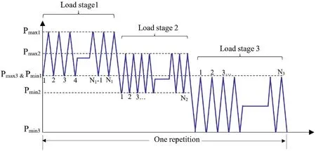
Fig.2.One repetition of variable amplitude loading history.
where Δai+1is the increment length (Δai+1= ai+1- ai); κ and γ are the constants based on a combination of the Paris constant;and Δkf(i+1)and Δkf(i)are the values of ΔKfat the lengths of ai+1and ai,respectively.
Δkf(i+1)is undefined in the DDM calculation when the crack tip collides with the other boundary segments and growth stops(Fig.3b).Nevertheless,in this case,to improve the reliability of life estimation, Δkf(i+1)is predicted by assuming the same variation trend for the two last consecutive growth steps.Life estimation for the heterogeneous domains where the crack tip intersects the interface(as shown in Fig.3c)follows the same equation governing the homogeneous media, except that fatigue life is calculated discretely and proportional to the increment size corresponding to each material(Ni+1= (Ni+1)1+(Ni+1)2).In this case,the SIF range for the intersection is obtained by
where α and β(α+β=1)are the fractions of the growth increment(Δai+1).
4.Simultaneous growth and coalescence of cracks in heterogeneous media
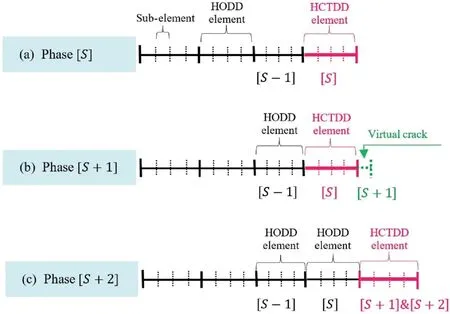
Fig.4.Representation of propagation for crack with low growth rate:(a)Real growth,(b) Virtual growth, and (c) Virtual growth change to real growth.
It is crucial to enable the numerical modeling of crack growth in heterogeneous domains containing several cracks.Each crack tip exhibits different SIF values under fatigue cyclic load,depending on its position and geometry.Therefore, this leads to various growth rates for each crack under the same loading conditions.The difference in growth rate values is modeled by assigning different growth increment values to each crack tip.In the DDM analysis,each growth increment is assumed to be a crack tip element.The size of the reference increment (Δamax) is assumed to be the maximum value of the growth length and corresponds to the crack tip with the highest growth rate ((GR)max) at each analysis step.Consequently,the growth increment size for other crack tips(Δa)is proportional to their growth rates(GR),and is selected as a fraction of Δamax:
This procedure performs well in the fatigue modeling of structures with multiple cracks.However,as the difference between the growth rates increases, the increment for crack tips with low growth rates will be very short and lead to difficulties in boundary element analysis.Hence, the principle of virtual crack growth is considered in the modeling process (Price and Trevelyan, 2014).Accordingly, incremental propagation for a domain with multiple cracks should meet two criteria.In BEM, heterogeneous and inconsistent elements adjacent to each other would be challenging.Therefore, the length ratio of adjacent elements should keep a convenient value during crack extension.The maximum ratio was selected to be 2.5.Furthermore, a minimum length (Δamin) is also assumed for the crack extension,and the increment’s length should be higher than the minimum length.
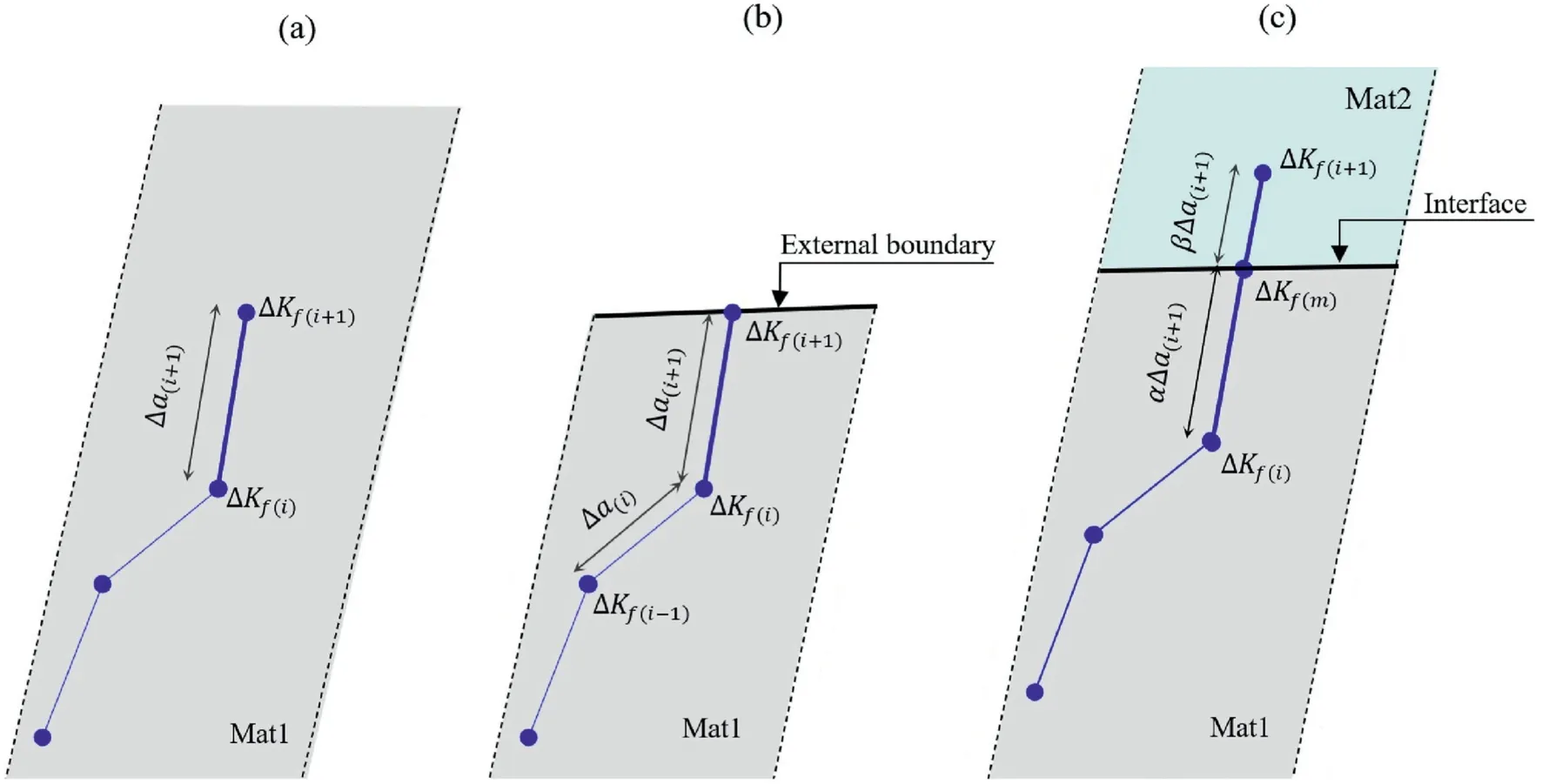
Fig.3.Incremental crack growth in (a) a homogeneous domain, (b) a homogeneous domain and intersection with external boundaries, and (c) a heterogeneous domain and intersection with an interface.
When the crack can grow, the crack tip develops based on the corresponding increments,and a new increment acts as the crack tip element in the calculations.Fig.4a exhibits this process for the growth step [S], in which a new increment is updated as an actual increment.Nevertheless, crack growth stops if the increment size does not meet the growth criteria.In this case,an increment is added to the crack tip, and its coordinates are updated.However, this growth is virtual,and the new increment is not applied as a crack tip element.Under these conditions, analyses are based on the last actual crack tip (ΔaS), and the new growth increments (ΔaS+2) are calculated accordingly (Fig.4b).This virtual growth process continues until the total distance between the virtual and real crack tips meets the growth criteria.Hence,the whole virtual interval(ΔaS+1+ΔaS+2)is applied as a crack tip element in the calculations(Fig.4c).Consequently,cracks with a low growth rate are modeled.
Coalescence and crack intersection with other segments are modeled for each growth step.Therefore,in order to maintain the convergence of crack paths, a circular area of a given radius dcis defined around each crack tip based on the characteristic length theory (Baˇzant and Pijaudier-Cabot,1989) to maintain a minimum distance between the crack tips and the other boundary segments.Radius dcis assumed to be equal to the maximum growth increment (Δamax).In the process, before each new growth step, the characteristic circle and model segments are specified.The crack tip’s intersection and coalescence conditions are met if the circular area around each crack tip meets the other boundary segments(Fig.5a).
When the crack tip collides with the external and internal boundary segments or another crack,the crack propagation will be stopped.Thus,the growth increment’s size depends on the distance of the crack tip from the coalescence location.Since crack growth termination does not apply to the crack tip-interface collision, the growth increment is initially extended up to the collision borderline in the calculated direction.If the calculated growth increment exceeds the traversed distance, the crack growth continues in another sub-region (Fig.5b).
When it was burning brightly the little hare said to the rabbit, Rabbit, my friend, throw me into the fire, and when you hear my fur crackling, and I call Itchi, Itchi, then be quick and pull me out
Crack growth in each growth step adds new elements to the DDM analysis.These elements are equal to the number of actual growth increments.In the case of crack coalescence, if the intersection point is an element point or segment point, it is used as a segment point in the analysis(Fig.6a,c and e).Furthermore,a new crack extension may intersect a pre-existing element in the boundary mesh.This point and both element points at its ends are utilized as segment points.Thus, the intersected element is modified, and two new elements are created.The influence coefficients and boundary conditions of the dissociated element are altered in calculations (Fig.6b, d and f).
5.Crack growth algorithm
This section describes the fatigue crack growth process through a specific algorithm(Fig.7).This algorithm consists of incremental growth, and a small crack advance is defined at each phase.It is used in Section 6 to model the numerical applications.
(1) The fatigue crack growth problem in heterogeneous media is solved under VAL and CAL by determining the geometric data, boundary conditions, elastic parameters, and material fatigue.The boundaries of the heterogeneous model are discretized based on the governing conditions.In this process, the elements of each segment should have the same length to improve computational accuracy.The initial crack tip element is assumed to be equal to the reference increment and nearly half the size of the HODD elements.Each phase of the analysis is proportional to one step of crack growth.
(2) In every analysis phase,a system of equations with multiple unknowns is formulated for each load part.The SIFs are calculated for each crack tip through the normal and shear displacement fields obtained by the mechanical solution of equations.These values are compared to the specific SIF.If they are higher than material toughness, unstable crack growth occurs.It is identified as a rupture, and the analysis stops.Once both load parts have been completed, the SIF range and a proper propagation angle are obtained for eachload stage.A simple scheme based on the equivalent SIF range is also employed for the VAL condition.
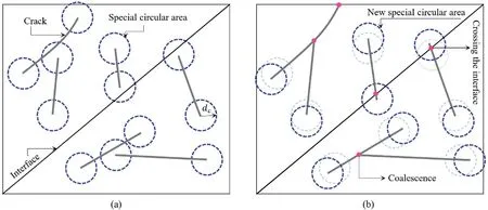
Fig.5.(a) Dissipation circle area for phase S, and (b) New dissipation circle area and coalescence point for phase S+ 1.

Fig.6.Representation of the change in a discretized domain when cracks intersect with(a)element point of external boundary,(b)pre-existing element of external boundary,(c)segment point of another crack, (d) pre-existing element of another crack, (e) element point of interface, and (f) pre-existing element of the interface.

Fig.7.Diagram for fatigue crack growth and life estimation of heterogeneous media.

Fig.8.(a) Dimensions and boundary conditions of the tensioned heterogeneous specimen with a horizontal single edge crack, and (b) Discretization of boundary using HODD elements and HCTDD element.
(3) To calculate the structural life, the number of cycles corresponding to the crack tip with the highest growth rate in the previous phase is assumed as the reference for each growth phase(Eq.(18)).The crack grows when the SIF range of each crack tip is higher than the threshold (ΔKth).The growth rates higher than the critical level (CL) (nearly 0.5-1 mm/cycle) are regarded as structural failure, which stops the analysis.
(4) As mentioned in Section 3,especially for multiple cracks,the relative growth rates and the crack coalescence affect the growth increment size in the next phase.Each increment is determined by considering all of these factors.Finally, it is updated based on its length as an actual/virtual increment.Moreover,adding increments as new linear segments to the crack tip leads to changes in the structure of the original segments,and the actual growth increments are meshed as a crack tip element or an ordinary element.Therefore, the model proceeds to the new phase by starting again from step(2).
6.Numerical applications
In this section, three applications of fatigue crack propagation are presented to demonstrate the efficiency and robustness of the procedure described in the previous sections.The heterogeneous domains have been affected by CAL and VAL.In these examples, it has been tried to gradually increase the complexity of applications to show the competencies and capability of the proposed method step by step.The first example simulates the fatigue crack growth in a heterogeneous specimen with an inclined interface.The fatigue crack growth in the heterogeneous domain under VAL conditions is examined in the second example.Finally, the last application evaluates the proposed method’s efficiency for fatigue propagation of multiple cracks in the heterogeneous structure.
6.1.Fatigue crack growth in a heterogeneous specimen with an inclined interface
This example presents a simple specimen to validate the efficiency of the proposed method in analyzing a 2D heterogeneous domain.This structure is composed of two materials (I and II),which are bonded together through an inclined interface.A rectangular plate with a width of 2w = 20 mm and a height of 2l = 80 mm is considered for numerical modeling.The angle of the interface is 30°relative to the horizon surface.The specimen contains a single horizontal edge crack with an initial length of 2a = 2 mm in the sub-region I.Fig.8a illustrates the geometry of the structure and crack location.A cyclic tensile load with a maximum value of 10 MPa and stress ratio R = 0 is applied to the upper and lower boundaries of the specimen.The Poisson’s ratio for two materials is the same and equal to ϑ = 0.3.Two elastic moduli of 10 GPa and 40 GPa are considered.The results are obtained for two distinct analyses,once with E1/E2= 4 and another with E1/E2= 1/4.The constant parameters of fatigue law (Paris and Erdogan,1963) are defined as C1= C2= 1.67×10⁻¹²and m1= m2= 3.23 (da/dN in mm/cycle and ΔK in MPa m0.5).The boundaries and the cracks are discretized into 10 linear segments (Fig.8b).The length of the crack tip segment(S9)is equal to 0.5 mm,which is assumed as the maximum size of the growth increment.
Fig.9 illustrates the crack growth path and the normalized SIFs against the crack length for both scenarios (E1/E2= 4 and 1/4).The crack propagation process is represented by 24 increments with a length of 0.5 mm.As can be seen,when the elastic modulus of sub-region I is lower than that of sub-region II,the crack growth is limited to sub-region I(Fig.9a).In this case,the crack first grows in the straight direction, the crack growth path changes when the crack tip approaches the interface,and then it continues to grow inline with the interface of two materials instead of entering subregion II.As shown in Fig.9b, the shearing mode of SIF (KII) is too small in this scenario and has an almost constant value in the entire crack propagation process.However,the opening mode of SIF(KI)is relatively higher, and this parameter is increased uniformly with the crack growth.The growth conditions are based on the opening mode;nevertheless,it should be noted that the ratio of|KII|to KIis not zero and takes a value between 0.0009 and 0.02.
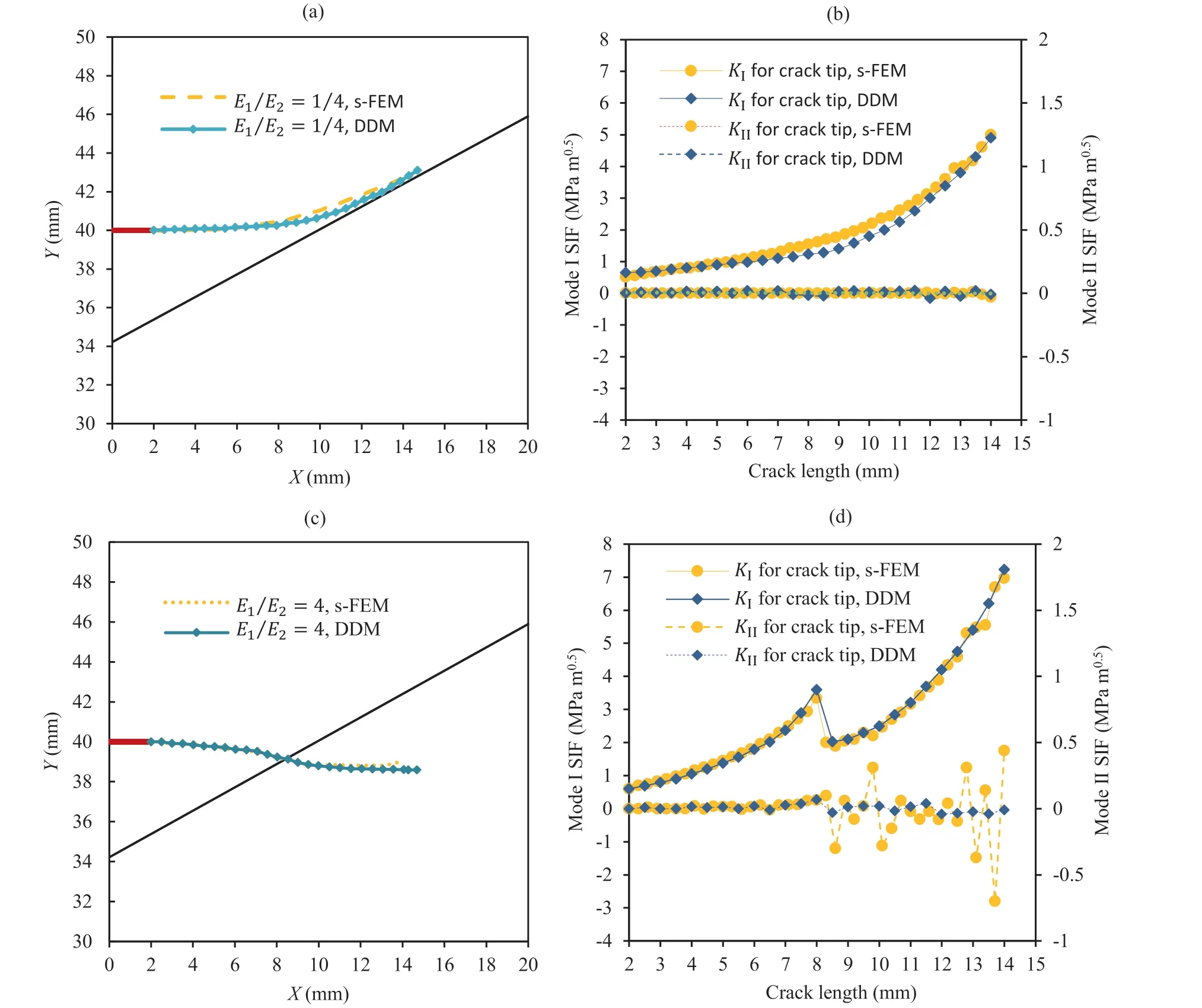
Fig.9.Numerical results of the heterogeneous specimen with a single edge crack: (a) Propagation path when E1/E2 = 1/4, (b) Distribution of SIFs when E1/E2 = 1/4, (c)Propagation path when E1/E2 = 4, and (d) Distribution of SIFs when E1/E2 = 4.
In the second scenario,where the elastic modulus of sub-region I is greater than that of sub-region II (E1/E2= 4), the crack propagates in sub-region I.It passes through the interface and enters sub-region II (Fig.9c).This process of crack growth and its associated changes can be observed in SIF curves (Fig.9d).At the beginning of crack growth up to 8 mm length,the variation trend of SIF curves(KIand KII)is similar to the first scenario(E1/E2= 1/4).The ratio of|KII|to KIis in the range of 0.007-0.02.When the crack length reaches 8.5 mm,the changes in the material surrounding the crack tip cause changes in SIF values.The graphs represent an obvious reduction in the values of KIand KII.Following the crack growth in sub-region II, the value of KIincreases gradually while the value of KIIremains nearly constant.However, KIIcanoccasionally exhibit negative values,indicating that the crack tends to change its path and grow perpendicular to the cyclic stress.The s-version FEM (s-FEM) analysis results of this example (Kikuchi et al., 2014) are also presented in Fig.9.As can be observed, the results of crack growth path curves are in good agreement.
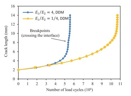
Fig.10.Life prediction result at the heterogeneous specimen with a single edge crack for two scenarios (E1/E2 = 4 and 1/4).
Finally, Fig.10 demonstrates the structural life prediction for studied scenarios.The number of cycles has been calculated concerning SIF values.In the case where the elastic modulus of subregion I is higher than that of sub-region II, the life estimation is about 5.5 × 10⁶, which is half of the other scenario.A specific increment corresponds to an inflection point on the life curve for second scenario (E1/E2= 4).This increment is correlated with crossing the interface and entering sub-region II, which has resulted in a sudden shift in SIF and life cycles.
6.2.Heterogeneous specimen containing edge crack under VAL condition
The second example investigates the fatigue crack growth in the heterogeneous medium under VAL conditions.The model is made of two dissimilar materials (I and II) bonded by a vertical interface.Details of this specimen can be seen in Fig.11a.The length of both sub-regions is the same and equal to 2l = 48 mm.The width of these sub-regions is w1= 8.2 mm and w2= 3.8 mm,respectively.The specimen comprises a single edge crack with 2a = 6 mm length in sub-region I.The crack direction is perpendicular to the loading.The domain is fixed on the lower boundary in both x and y directions,and a variable amplitude load is applied on its upper edge.The maximum and minimum stress values and the number of load cycles associated with each load stage are indicated in Fig.11b.The stress ratio for both load stages is R=0.1.The mechanical properties,including Poisson’s ratio and elastic modulus, and the parameters associated with the fatigue law (Walker, 1970) in each region are presented in Table 1(da/dN in mm/cycle and ΔKeqin MPa m0.5).

Table 1Mechanical and Fatigue parameters for each sub-region of heterogeneous specimen.
For the initial discretization of the model, sub-regions and the crack were modeled with 10 linear segments.They involved the tip,crack body,external boundaries and interface.The crack tip element with length of 0.5 mm was utilized as the reference increment size.In addition, two other lengths were used to evaluate the impact of growth increment size on SIFs and their associated life.
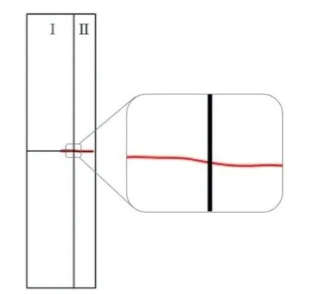
Fig.12.Crack growth path of heterogeneous edge cracked specimen under VAL condition.
Fig.12 depicts the crack growth path during nine increments.Initially, the crack follows a short straight path and then deviates slightly from that path.After crossing the interface, the tip enters the sub-region II and gradually propagates in its original direction.In this example, the crack path deviation is insignificant.The evolution of the SIF during the crack propagation process is shown in Fig.13.As can be seen, the fifth increment (for Δa = 0.5 mm),which corresponds to the crack tip that traverses the interface,exhibits abrupt variations in SIF.It indicates that the medium surrounding the crack tip has changed.In this figure, the analysis results with increments of Δa = 0.3 mm and 0.8 mm are alsodisplayed.It is evident that the SIF range of Δa = 0.3 mm demonstrates a minimal difference from the results obtained with Δa =0.5 mm,except in the immediate proximity of the interface.These results also apply to the 0.8 mm increment.Differences in the SIF range are crucial when they result in substantial life estimation changes.The ultimate life for three increment sizes is about 14,000 cycles (Fig.14).In fact, the difference between the results is negligible.These results demonstrate that using higher-order elements improves computational accuracy,and the necessity of using smallsize increments is disregarded.
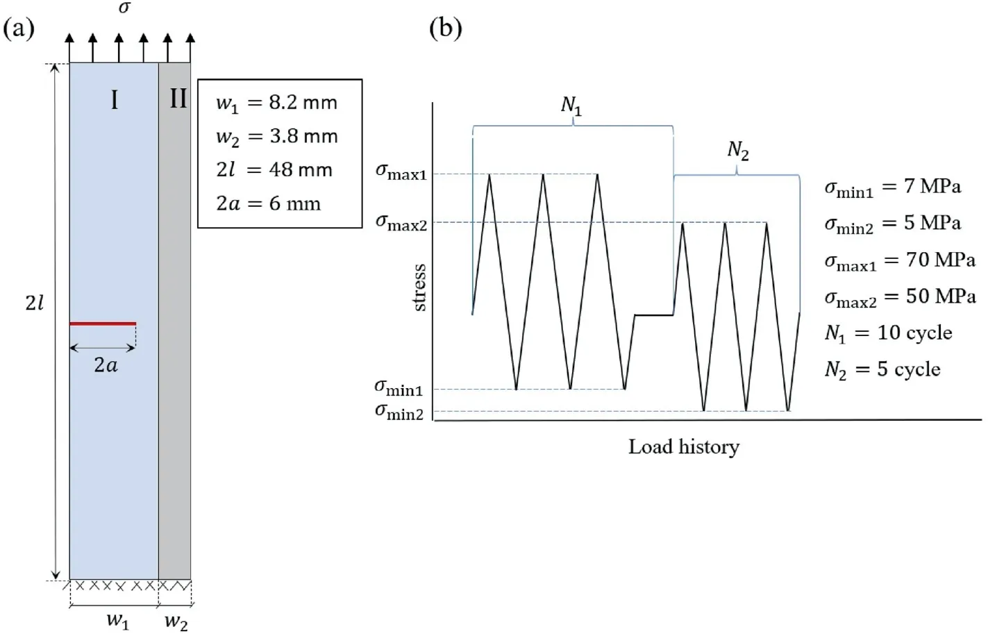
Fig.11.(a) Dimensions and boundary conditions for heterogeneous edge cracked specimen subjected to VAL, and (b) Schematic scheme of cyclic load history.

Fig.13.Variations of the SIF range with the crack length for edge cracked specimen under VAL condition.

Fig.14.Life prediction for three increment sizes of edge cracked specimen under VAL condition.
6.3.Fatigue in the heterogeneous specimen with multiple cracks
The last example examines the specimen,which is composed of dissimilar materials and evaluates the efficiency of the proposed method for fatigue phenomenon in a heterogeneous region with multiple cracks.The numerical model considers a rectangular specimen with a length of 2l = 200 mm and a height of 2h = 100 mm.It is a heterogeneous specimen with two different materials,and boundary δ as the interface between two sub-regions is specified at the height of h = 50 mm.Fig.15 illustrates the geometrical details of this medium.The specimen has two circular holes of r =10 mm in diameter along the centerline, and the left end of the domain is fixed in both directions.A cyclic load with R=0 is applied to the medium’s right edge, and its components in the x- and ydirections are 9 MPa and 1 MPa, respectively.A total of 15 cracks with an average length of 3 mm are distributed in sub-regions I and II, and four cracks emanate from the holes.The Poisson’s ratio for both sub-regions is ϑ = 0.3.The elastic modulus of sub-region I is 30 GPa,and simulations have been conducted for three scenarios of(1) E1/E2= 1, (2) E1/E2= 1/3, and (3) E1/E2= 3.Constant parameters of fatigue law (Paris and Erdogan, 1963) are defined as C2=C1= 10-9and m2=m1= 2.6 for both materials (da/dN in mm/cycle and ΔK in MPa m0.5).The external and internal boundaries, interface and cracks are specified with 51 segments.The length of each initial crack tip element is assumed as the maximum increment and equal to 0.75 mm.The minimum length increment is 0.3 mm in fatigue analysis, and the maximum value for the allowable length ratio of neighboring elements is 2.5.This model’s cracks propagate under cyclic loading due to the fatigue phenomenon.
Fig.16 presents the results of crack evolution during the cyclic loading process for three scenarios.The crack growth in scenario 1,which represents the homogeneous condition, is illustrated in Fig.16a.In this case,the cracks that exhibit a greater growth rate are close to the bottom edge of the structure.These results are in line with expectations because these cracks are more stressed due to the tensile and bending effects of the applied load.In the initial phases,crack 1 is critical,with the highest growth rate.Afterward,crack 5 becomes predominant.It is placed in a region with higher stress.This crack initially moves toward the lower edge and intersects it.Then,it propagates upward and crosses the interface.In the growth path,crack 6 also coalesces with this crack.Finally,after 120 growth phases, it reaches the upper edge of the domain.The evolution procedure of crack growth for scenario 2 is shown in Fig.16b.As mentioned before,sub-region II inherently has a higher stress level in the homogeneous case.In this scenario, the higher elastic modulus acts as an additional factor that increases this stress level.In this case, crack 5 is also critical and goes through a path similar to scenario 1.Nevertheless, the growth rate for cracks of sub-region I is significantly lower than sub-region II, and in most analysis phases, their growth is virtual.Ultimately, the crack growth was analyzed for the case in which the elastic modulus of material I is higher than that the material II(case 3),and the results are presented in Fig.16c.In this scenario, the sub-region I experiences a higher stress level, and crack 3 has the maximum growth rate as the critical crack in the structure.Cracks 2 and 3 grow and deviate towards each other after 15 progressive steps.Therefore,after 23 phases,crack 3 coalesced with crack 2.Then crack 4 grows as the dominant crack in the remaining analysis steps and reaches the upper structural boundary after 37 growth phases.
Fig.17 demonstrates the SIF range against the cumulative crack length for the critical crack tip at each growth phase.For case 1,the curve in the first two phases (up to 1.5 mm length) is associated with crack 1, and the remaining part is related to crack 5.A small change around the 11th phase is observed in the SIF range when the crack tip intersects the lower edge.The behavior of the curve for case 2 is similar to case 1 because their critical cracks are the same.However, the SIF values for case 2 are greater due to the higher stress levels in region 2.This curve exhibits an abrupt reduction at the length of 41 mm.It represents the material change surrounding the crack tip.The curve trend after the crack tip penetrates to subregion I almost agrees with the homogeneous case, as theremaining conditions are the same for both scenarios.For case 3,the response corresponds with crack 3.Its curve with lower SIF relative to other cases is specified in 23 phases.Despite the relatively uniform slope of this curve, an increase in the length of 12 mm is observed because cracks 2 and 3 become closer to each other, and consequently, coalescence occurs.
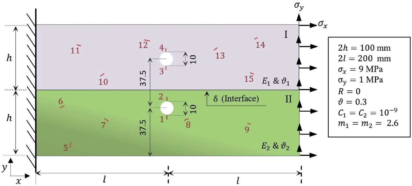
Fig.15.Dimensions and boundary conditions for an heterogeneous domain with multiple cracks.
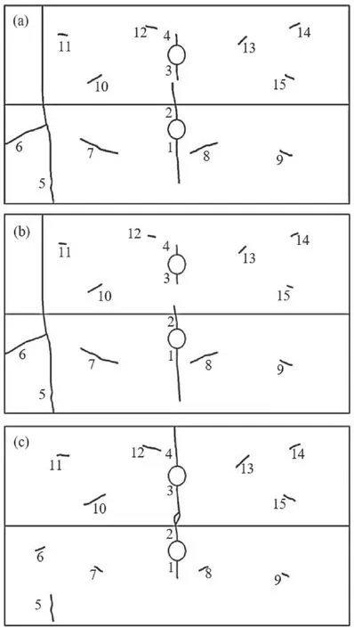
Fig.16.Crack propagation for multiple cracks at heterogeneous domain: (a)E1/ E2 =1, (b) E1/E2 = 1/3, and (c) E1/E2 = 3.
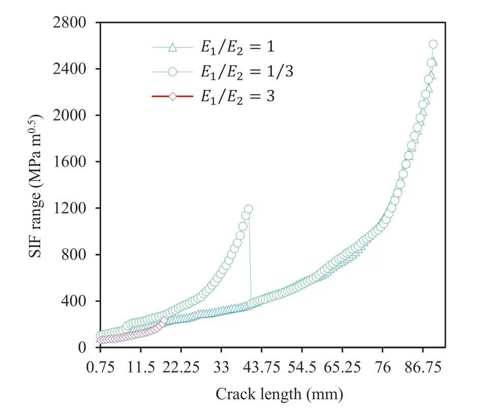
Fig.17.Variations of SIF range with crack length at the heterogeneous domain with multiple cracks.
Fig.18 shows the evolution of crack growth versus life(in cycles)for three scenarios.These curves have been calculated using the values of SIFs associated with the critical crack at each progressive step.Scenario 2 displays the lowest values for the structural life.The life estimation depends on the SIF range.This parameter is the only variable in different scenarios of this example,and considering its values in Fig.18,these results are not far-fetched and agree with the expected results.This example demonstrates the efficiency of the proposed method in modeling fatigue crack growth and life estimation for heterogeneous media with multiple cracks.Moreover, this numerical method performs well in simulating the intersection and coalescence phenomena.
7.Conclusions
Brittle materials undergo fatigue failure at stresses below their ultimate strength under cyclic loads.These materials, such as rock and concrete, contain inherent flaws, and cracks are inevitable defects.Predicting the crack growth path and fatigue life is essential to prevent catastrophic events in these materials.The present study proposed a higher-order DDM to model the simultaneous growth of several fatigue cracks to analyze fatigue in heterogeneous brittle geomaterials.The numerical process was established by integrating LEFM principles,fatigue laws,and the incorporationtechnique of sub-regions with the primary concepts of DDM.Cubic variations of DD were simultaneously used in both ordinary and crack tip elements to improve the accuracy of life analysis.Walker and Paris laws were used as the governing equation of fatigue to model incremental propagation and life estimations of structures.Finally, three numerical examples were presented to evaluate the proposed method.Various applications were addressed to examine the proposed technique;the complexity of the examples gradually increased to evaluate the efficiency and effectiveness of the DDMbased method.
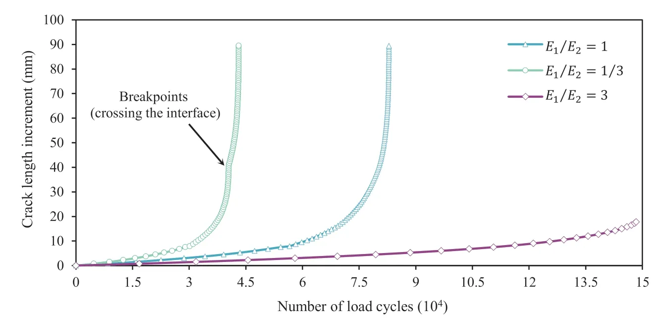
Fig.18.Life prediction results in an heterogeneous domain with multiple cracks.
The effects of various material properties on crack growth behavior were well demonstrated.These effects manifested in both the crack propagation path and growth rates.However,crack path deflection where a crack tip traverses material interfaces was neglected.The variation of the SIF range was evident in the results when the crack propagated from one sub-region to another.In the simulation of the heterogeneous domains, the life curves showed the breakpoints caused by utilizing discrete incremental life equations defined for transition situations.At these points, the trend of the curves changed with the material properties and fatigue characteristics of the new medium surrounding the crack tip.The domains were influenced by both CAL and VAL.The VAL conditions were modeled using the equivalent SIF range.In these investigations,the sequence effect and overload were also ignored.In the analysis of domains containing multiple cracks, the difference in the growth rate of cracks in various positions was successfully represented.In addition, growth behaviors were described by considering cracks’ interaction and coalescence phenomena.Except near the interfaces of heterogeneous domains, the differences between the SIF ranges of various increments were insignificant due to the use of cubic elements.However, these differences did not significantly impact the life calculations,and the necessity of using small increments is eliminated.
The concepts and techniques presented in this study can be extended to hydro-fracture topics.Furthermore,future studies can consider the behavior of the fracture process zone and address its influence on fatigue crack growth behavior in a brittle material.
Declaration of competing interest
The authors declare that they have no known competing financial interests or personal relationships that could have appeared to influence the work reported in this paper.
Appendix A.Supplementary data
Supplementary data to this article can be found online at https://doi.org/10.1016/j.jrmge.2022.12.001.
 Journal of Rock Mechanics and Geotechnical Engineering2023年3期
- Journal of Rock Mechanics and Geotechnical Engineering的其它文章
- Development of mathematically motivated hybrid soft computing models for improved predictions of ultimate bearing capacity of shallow foundations
- Effects of intermediate stress on deep rock strainbursts under true triaxial stresses
- A post-peak dilatancy model for soft rock and its application in deep tunnel excavation
- Combined load bearing capacity of rigid piles embedded in a crossanisotropic clay deposit using 3D finite element lower bound
- Long-term decay of the water pressure in the osmotic tensiometer
- Predicting and validating the load-settlement behavior of large-scale geosynthetic-reinforced soil abutments using hybrid intelligent modeling
