Coseismic site response and slope instability using periodic boundary conditions in the material point method
Abdelrahman Alsardi, Alba Yerro
Department of Civil and Environmental Engineering, Virginia Tech, Blacksburg, 24060, Virginia, USA
Keywords:Coseismic site response Periodic conditions Time integration Material point method (MPM)
ABSTRACT This paper proposed the explicit generalized-α time scheme and periodic boundary conditions in the material point method (MPM) for the simulation of coseismic site response.The proposed boundary condition uses an intuitive particle-relocation algorithm ensuring material points always remain within the computational mesh.The explicit generalized-α time scheme was implemented in MPM to enable the damping of spurious high frequency oscillations.Firstly,the MPM was verified against finite element method (FEM).Secondly, ability of the MPM in capturing the analytical transfer function was investigated.Thirdly, a symmetric embankment was adopted to investigate the effects of ground motion arias intensity(Ia),geometry dimensions,and constitutive models.The results show that the larger the model size, the higher the crest runout and settlement for the same ground motion.When using a Mohr-Coulomb model, the crest runout increases with increasing Ia.However, if the strain-softening law is activated,the results are less influenced by the ground motion.Finally,the MPM results were compared with the Newmark sliding block solution.The simplified analysis herein highlights the capabilities of MPM to capture the full deformation process for earthquake engineering applications,the importance of geometry characterization, and the selection of appropriate constitutive models when simulating coseismic site response and subsequent large deformations.
1.Introduction
During earthquakes, soils are subject to irregular and multidirectional cyclic vibrations.Depending on the site characteristics,seismic waves can be either amplified or attenuated at site-specific frequencies.The reliable evaluation of wave propagation is important to understand manifestations in soils and infrastructure.During slow intensityearthquakeshaking,soilbehaviorcan beapproximated to be linear and material damping is approximated to be negligible.One-dimensional(1D)wave propagation closed-form transfer functions are available for these small-strain wave propagation problems(Kramer,1996).However,under more intense shaking,soil behavior can be extremely nonlinear.As such,the equivalent-linear approach was developed as a simple way to handle nonlinear soil behavior.The stiffness modulus and damping ratio are varied in an iterative manner to obtain an“effective”strain induced in a soil layer using the linear elastic closed-from solutions (e.g.Idriss and Seed, 1968; Schnabel et al., 1972).Although this approach is computationally efficient compared to other numerical techniques, the secant stiffness modulus and damping ratio are implicitly assumed to remain constant for the entire duration of the shaking.This particularly represents an important limitation of the method because it fails to reflect accurate soil behavior.Additionally,the equivalent-linear approach is incapable of considering case scenarios that involve soil-waterstructure interaction,staged construction,and complex geometries.
The rigid sliding block solution was proposed by Newmark(1965) to assess slope performance and to obtain the incurred runout due to seismic loading.Newmark(1965) assumed that soil behaves in a rigid-perfectly plastic manner across a well-defined slip surface, with no dynamic site response or strength loss due to shaking.The sliding mass exhibits displacement episodes when the factor of safety goes below unity.This model provides a simple method that requires only two input parameters, namely (a) yield coefficient(ky),as proxy for the threshold of dynamic resistance in units of g=9.81 m/s2,and(b)the acceleration-time history of the ground foundation.Practitioners often employ the pseudo-staticlimit equilibrium analysis to quantify the value of ky.For these reasons, the scope of the Newmark (1965) method is restricted to simple constitutive behaviors and geometries.Various researchers employed Newmark's approach to propose simplified regression equations which facilitate the calculation of permanent displacement, although all of Newmark's crude assumptions are retained(e.g.Jibson,2007;Saygili and Rathje,2008;Hsieh and Lee,2011;Lee and Green, 2015).To overcome some of the limitations, the“decoupled”approach was developed to overcome the rigid sliding mass assumption and to take into account the effect of dynamic response due to shear wave(S-wave)propagation upon permanent slip of the sliding mass (e.g.Makdisi and Seed, 1978; Lin and Whitman, 1983; Jibson, 1993; Bray and Rathje, 1998; Bray and Travasarou, 2007; Rathje and Antonakos, 2011; Bray et al., 2018).The most important limitation of the decoupled procedure is that the computation of the seismic response of the potential sliding mass is decoupled from the subsequent slip.For this,the“coupled”approach was developed to consider the role of internal shear deformation of the sliding mass upon the permanent displacement accumulation (e.g.Rathje and Bray, 2000; Bray and Travasarou,2007; Bray et al., 2018).The coupled approach solves the equation of motion using simplified viscoelastic-perfectly plastic elements which simulate the 1D deformation of the flexible sliding mass during the landslide.Besides the dynamic site response, the coupled approach inherits the other limitations of the Newmark and decoupled approaches (i.e.simple geometries and soil behavior).In contrast to Newmark's original approach, the decoupled and coupled simplified regressions provide only the final magnitude of permanent displacement with no indication of the time of sliding initiation or final mass stabilization.
Alternatively, numerical methods are often employed in geotechnical engineering to simulate coseismic site response using nonlinear constitutive models and complex geometries.Advancements in numerical mesh-based techniques incorporate nonlinear soil behavior that can successfully model small-strain boundary value problems associated with site response.However, these mesh-based techniques have limited capabilities when simulating large strains associated with post-failure deformations induced by strong-motion shaking (Alsardi et al., 2021).This is because of excessive mesh entanglement and distortion.Examples of such large strain applications include coseismic landslides, tunnel collapses, and liquefaction.To address large deformation in multiphase problems, in the last decade, the geotechnical engineering community has widely adopted the material point method(MPM)(e.g.Bandara and Soga, 2015; Yerro et al., 2015; Soga et al., 2016;Kularathna and Soga,2017;Alonso,2021;Feng et al.,2021;Salgado and Bisht, 2021).However, the MPM has been rarely used for the study of earthquake-triggered failures.Most of the current state-ofthe-art models of large deformations rely on simulating small-scale shaking table experiments where fully reflective boundaries are generally accepted (e.g.Bhandari et al., 2016; Alsardi and Yerro,2021).When using fully-reflective boundary conditions, there are inherit numerical limitations which prevent the study of coseismic site response.This is because of the artificial wave reflections across the boundaries of the numerical domain.The 1D wave propagation solution using periodic boundary conditions plays an important role in simulating in situ free-field conditions in numerical simulations(Zienkiewicz et al.,1989a,b).This setup is depicted in Fig.1,whereby a free-field soil layer overlies bedrock.Periodic boundary conditions simulate a representative unit of the free-field soil layer.Recently,Feng et al.(2021)extended the use of MPM with free-field boundary conditions to simulate the Lower San Fernando Dam case study although there was no verification conducted to assess the implemented periodic conditions that serve to calculate the 1D free-field wave propagation solution.It should be noted that the numerical results using free-field boundary conditions are highly dependent on the accuracy of the used 1D wave propagation solution when using periodic boundary conditions(Nielsen,2006).As such, rigorous element-level verification of periodic boundary conditions in MPM is required to ensure that performance of the free-field columns is consistent with the results of analytical and other numerical techniques.

Fig.1.Schematic of in situ conditions to be simulated using periodic boundary conditions in a numerical model.
The MPM is well suited to simulate large deformations,but it is more computationally expensive than mesh-based approaches such as finite element method (FEM).This is due to the back-andforth information mapping between the nodes from the computational mesh and the material points(i.e.integration points).Also,the use of the MPM is traditionally accompanied with the explicit forward Euler-Cromer (MPM-EC) time integration scheme which may result in spurious high-frequency numerical oscillation when simulating earthquake engineering problems such as coseismic landslides (Kontoe et al., 2008a; Tran and Solowski, 2019).Recent advancements in time integration schemes offer user-controlled high frequency numerical noise elimination to stabilize these oscillations (Chung and Hulbert, 1993; Hulbert and Chung, 1996;Kontoe et al., 2008a).Notably, the explicit generalized-α time integration scheme was developed by Hulbert and Chung (1996)and was adapted for MPM by Tran and Solowski (2019).This time scheme is second order accurate, self-staring, and enables usercontrolled damping.The generalized-α scheme is a more general implementation of the commonly employed Newmark-β scheme in earthquake dynamics (e.g.Chopra, 2007).To the authors’ knowledge, the use of periodic boundary conditions and explicit generalized-α time scheme in MPM has never been verified for site response against element-level FEM soil column and the linear analytical site response solution.This is a crucial step to simulate free-field earthquake engineering problems accurately.
The objective of this paper is to propose a verified MPM framework capable of accurately simulating the full deformation process of earthquake-triggered failures.To achieve this goal, periodic boundary conditions together with the explicit generalized-α time integration scheme were implemented.Contrary to the implementation of Feng et al.(2021), the periodic boundary conditions proposed herein were attached to a moving mesh and were equipped with a particle relocation algorithm to improve the accuracy of the solution.The paper is organized as follows.Firstly,the implementation of the periodic boundary conditions and the MPM computational cycle in the explicit generalized-α time scheme(MPM-GA) were presented.Secondly, the numerical model of a linear-elastic column was used to verify the MPM-GA implementation with periodic boundary conditions against the FEM using Plaxis software(Brinkgreve et al.,2016).The MPM results were also compared with an analytical linear site response solution in the frequency domain.Thirdly, the periodic boundary conditions were leveraged to conduct a parametric analysis to investigate the effect of the ground motion intensity, model dimensions, and material brittleness on the coseismic slope instability of a symmetric slope embankment.Finally, the numerical results were compared against Newmark rigid sliding-block solution (Newmark,1965).
2.Advancements in MPM for earthquake-triggered site response
The MPM is a particle-based numerical tool whereby a continuum is discretized into a set of Lagrangian points,each so-called a material point (MP) (Sulsky et al.,1994).The MPs move within an Eulerian computational mesh and represent the deformation of the continuum.Fig.2 summarizes the MPM computational cycle usually integrated explicitly in time and it involves:
(a) Interpolating state variables from MPs to nodes,
(b) Solving the governing dynamic momentum balance equations at the nodes,
(c) Remapping the nodal solution back to the MPs,and
(d) Updating the final MP positions and state variables.
The computational mesh does not usually store any information and can be moved or regenerated after each time step.In the MPM framework,the boundary conditions can be applied on the nodes or on the MPs.Some of the numerical limitations of the original MPM framework include the generation of spurious noise when integrating upon the mobile MPs that cross from one element to another (i.e.cell-crossing noise) (Bardenhagen and Kober, 2004;Dhakal and Zhang,2016).This is because of the discontinuity in the shape function derivatives when using lower-order elements.Several MPM variations have been proposed to alleviate the cellcrossing noise errors (e.g.Bardenhagen and Kober, 2004;Sadeghirad et al.,2011;Moutsanidis et al.,2020),including the use of mixed MPM-Gauss-Point integration, which allows the computation of an averaged incremental stress using optimally positioned Gauss points (Jassim, 2013).Another limitation of the use of advanced absorbing boundary conditions in MPM when the deformations are large can be the sporadic incidents of MPs leaving the background computational mesh, which often terminates the numerical simulations.Recent developments for earthquakeinduced shaking include the advancement of boundary conditions to prescribe seismic action in terms of acceleration, velocity, and displacement (e.g.Bhandari et al., 2016; Ering and Babu, 2016;Alsardi and Yerro, 2021; Alsardi et al., 2021) or traction (e.g.Feng et al., 2021).In particular, for this research, an in-house version of the Anura3D open-source software was used (Anura3D, 2021).Details of the MPM one-phase formulation and implementation in Anura3D can be found in Fern et al.(2019).Recent advancements in the simulation of seismic shaking implemented within the Anura3D framework are described in Alsardi et al.(2021).They proposed to prescribe the ground motion as a time-dependent Dirichlet boundary condition applied at the nodes of a moving background computational mesh (i.e.the mesh rigidly moves following the input ground motion).This approach,also used in this paper, is seen to reduce the number of cell-crossing occurrences because there is less relative movement between the MPs and the mesh.
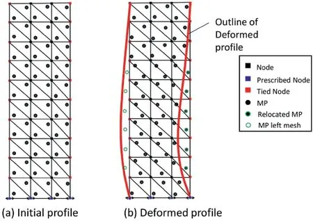
Fig.3.Schematic of the particle relocation technique employed with periodic boundary conditions.
2.1.Periodic boundary conditions in MPM
The 1D site response analysis due to shear wave propagation in a soil column is commonly adopted to understand free-field soil amplification response.This analysis is often considered as an element-level verification approach for numerical and constitutive models (Toloza, 2018; Taborda, 2011; Chen, 2020).In this paper,periodic boundary conditions were implemented in the MPM framework to simulate 1D site response in a two-dimensional(2D)problem.The main objective of the periodic boundary condition is to ensure identical displacements (i.e.solution in Fig.2b) for the nodes at the same spatial level from both lateral sides of the model.This constrains the model to simulate a free-field domain through the effect of periodicity.Similar to mesh-based methods, periodic boundary conditions can be implemented in the MPM frameworkby overwriting the degrees of freedom of the corresponding nodes to obtain the same nodal solution.The implementation enables the sharing of information between the tied nodes.Effectively, the mass and the forces of these tied nodes are summed so that they are identical.A single acceleration, velocity, and ultimately displacement value is obtained for each set of nodes.The nodal solution is mapped to the MPs within the computation cycle (Fig.2c).
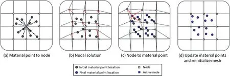
Fig.2.MPM computational cycle where squares represent mesh nodes and circles represent MPs.(a) Mapping information from MPs to background mesh nodes, (b) Solving dynamic momentum balance equation to obtain nodal accelerations, (c) Updating velocity and momentum balance at the MPs from nodal acceleration, and (d) Updating state variables at MPs using constitutive equations and mass balance equations.Nodal values are discarded.
Under large deformations due to strong-motion shaking in level ground conditions, the MPs may leave the computational domain which terminates the simulation.An initial intuitive approach used by others (e.g.Feng et al., 2021) is to increase the element size to provide more space for the MPs to move.However, spatial discretization refinement can impose an element size restriction based on the maximum frequency content of the ground motion(Kuhlemeyer and Lysmer, 1973).Also, the use of coarse mesh compromises the accuracy of the solution.In the implementation herein, a novel and intuitive particle relocation technique was incorporated to ensure that the MPs remain within the computational domain.This technique is schematically illustrated in Fig.3.When the MP moves out of the computational domain due to deformation (see Fig.3b), the MP is relocated to its corresponding periodic position by subtracting the repeating unit width.
2.2.Explicit generalized-α time integration scheme
Given the suitable selection of time scheme parameters, the generalized-α time scheme(Chung and Hulbert,1993)is capable of achieving an optimal combination of maximum dissipation of high frequency numerical noise but minimum low frequency dissipation.The fundamental idea of this time scheme is evaluation of the various terms of the equation of motion at different points within the time step.Hulbert and Chung (1996) proposed this conditionally-stable explicit version of the generalized-α time scheme by setting the numerical parameter corresponding to the internal forces computation (αf) to zero.The explicit scheme is recommended to be used for problems where the time step (Δt)needed for sampling accuracy is of the same order of the critical time step (Δtc) (e.g.wave propagation problems in compressible and drained media).Tran and Solowski(2019)adopted the explicit algorithm using in MPM, and their work forms the basis for the MPM-GA implementation presented herein.In this explicit time scheme,the user can control the damping by varying the values of Δt and minimum spectral ratio (ρb).Kontoe et al.(2008a) recommended the use of ρb=9/11 with a time step of Δt=0.01 s which achieves 18.2% of damping and prevents excessive dissipation of physical high frequencies.However, this recommendation is oriented towards the implicit generalized-α scheme and it is not strictly applicable to the explicit version herein.
Fig.4 shows the variation of the spectral ratio (ρ) versus the dimensionless angular frequency (Ω), which equals the product of the generated angular frequency(ω)and the chosen time step(Δt).When ρ=1,it corresponds to no damping.By contrast,when ρ=0,complete damping of the corresponding frequency is achieved.The maximum damping associated with the minimum spectral ratio(ρb) occurs at the bifurcation limit (Ωb).The value of ρ increases after reaching Ωb,experiencing a reduction in the damping beyond the bifurication limit.The stability limit (Ωs) is the limit at which ρ=1 beyond the Ωblimit.The existence of frequencies beyond the Ωslimit results in amplification of those frequencies which ultimately might lead to an unstable numerical model.The stability of the model using MPM-GA scheme is conditional on the selection of Δt and ρbsuch that the frequencies beyond ρblimit are kept to minimum.Since this is an explicit scheme,the time step increment(Δt) must also satisfy Δtcusing the Courant-Friedrichs-Levy (CFL)condition (Kafaji, 2013; Yerro et al., 2015, 2022) (Δt ≤ Δtc).
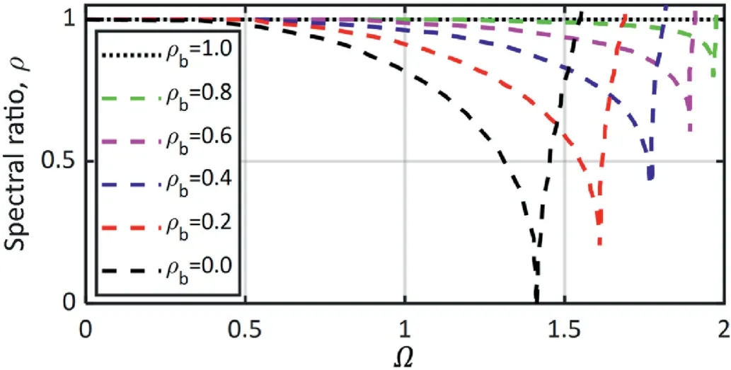
Fig.4.Spectral ratio variation with dimensionless angular frequency(Ω = Δt = 2πfΔt, f :frequency.) (Chung and Hulbert,1993).The plots are shown for different bifurcation spectral ratios.
Note that the Ωband Ωsare both a function of the ρband do not depend on the chosen time step as presented in their closed form in Eqs.(1) and (2), respectively.All other numerical parameters (αm,βmand γ) in the time scheme can be calculated as a function of ρbusing Eqs.(3)-(5), respectively.The reader is referred to Chung(1992) for details regarding the derivation of Eqs.(1)-(5).
Overall, the advantage of this explicit MPM-GA formulation is that it does not require expensive iteration to keep a desired high frequency damping.The drawback is that it requires calibration to ensure the stability of the solution for the level of damping required.The MPM-GA algorithm is primarily based on storing the accelerations at the nodes to obtain an initial acceleration () at time t.is assumed to be zero in the first time step.The dynamic momentum balance is then solved at the nodes to compute an intermediate acceleration () at t = Δt(1 - αm).This algorithm linearly interpolates the initial and intermediate solution to obtain the final acceleration () at t = t+ Δt.In the implementation herein and contrary to Tran and Solowski (2019),the acceleration-to-velocity integration was at the MP-level similar to the fluid implicit particle (FLIP) scheme.This approach is recommended by Brackbill et al.(1988) because it reduces numerical diffusion when the nodal solution is remapped to the MPs.The computational cycle of the MPM-GA is presented as follows(noting that the subscripts denote node or MP index, and superscripts denote the time of the evaluated term):
(1) Compute nodal mass(Mti)by mapping MP mass(mMP)using basis functions()and looping across the number of active elements associated with the node (nel) and the number of MPs located within these elements (nMP) by
(2) Compute the rate of change of momentum () by
(3) Compute intermediate nodal acceleration () at the nodes by dividing the rate of change of momentum by the mass using
(4) Compute final nodal accelerations () through linear interpolation by
(6) Compute nodal velocity () by dividing nodal momentum by nodal mass by
(7) Compute incremental nodal displacementsby Eq.(12) and subsequently multiply by the basis function gradients()to obtain MP incremental strain()by Eq.(13).
(8) Compute final MP displacement () by
(9) Store the nodal accelerations()in the subsequent time step.
In this paper, we adopted a Courant number of 0.95 for all simulations, which means Δt = 0.95 Δtcaccording to the CFL condition.The value of ρbcan be varied for each simulation with the goal of damping out high frequencies(above 35 Hz consistent with Kontoe et al.(2008a),while ensuring that Ωbis not reached.If this is not possible due to the CFL critical time step restriction,a reduced value of ρbis adopted (note that the value of ρb= 0 is always avoided to prevent a very low value for the bifurcation and stability limits).The frequency f where dissipation starts to occur is calculated using Eq.(15).In each example herein,the value of the used ρband Δt is documented with the corresponding damped out frequency range.
3.Ground motions
Three ground motions(I,II,III)from the PEER database(Ancheta et al., 2013) were adopted in this paper as plotted in Fig.5.These recordings were selected because of their rich frequency content(up to 30 s-1)which is expected to engage a range of modes in the soil column to enable the numerical back calculation of the transfer function (Kontoe et al., 2008a).Note that the goal is to compare against an analytical solution and not to reproduce a particular site response case study.As such, specific ground motion characteristics, and their site class and place of occurrence are not relevant herein, but are documented in Table 1 for the reader to facilitate their retrieval from the PEER database if desired.Iais computed for each ground motion as defined in Eq.(16)where g=9.81 m/s2.The value of Iaprovides a measure of the energy delivered by the input ground motion as a function of its acceleration (at), across the shaking duration (d).
In addition to the PEER recordings, a Gabor wavelet (Gabor,1946) acceleration load (aw) defined by Eq.(17) is also considered in the examples presented herein.The wavelet shape parameters(αw, βw,γw) used in the analysis are documented in Table 2.The trapezium rule was used to integrate the acceleration of all time histories and obtain the velocity time histories to be applied at the base of the model.Additionally, linear baseline correction was applied to eliminate any observed displacement drift.The wavelet is generated at the fundamental frequency (f0) of the soil column.
4.Coseismic response of horizontal ground with MPM
The goal of this section is to verify the performance of the proposed MPM formulation in horizontal ground profiles.
4.1.Numerical model
A plane-strain 10 m soil column (labeled herein “SC”) is considered to simulate site response of an infinitely horizontal and homogeneous ground surface due to 1D wave propagation using MPM (Fig.6a).This model is also generated in FEM with Plaxis(Fig.6b).The MPM model employs linear triangular elements,and the FEM model employs quadratic triangular elements.The effect of the basis function order is not significant in this problem since a linear-elastic constitutive model was used.Parameters of all the soilcolumn models are documented in Table 2.A fine element size of 0.25 m was used equal to one-tenth times the minimum wavelength of the shear wave generated by the ground motions(Table 1)in the considered materials (Table 2).This spatial discretization approach is consistent with Lysmer and Kuhlemeyer(1969),and is commonly adopted in mesh-based numerical techniques (e.g.Kontoe, 2006; Zalachoris et al., 2021).

Table 1Summary of ground motion details used in the analysis.

Table 2Summary of cases simulated in MPM and FEM using soil column model.
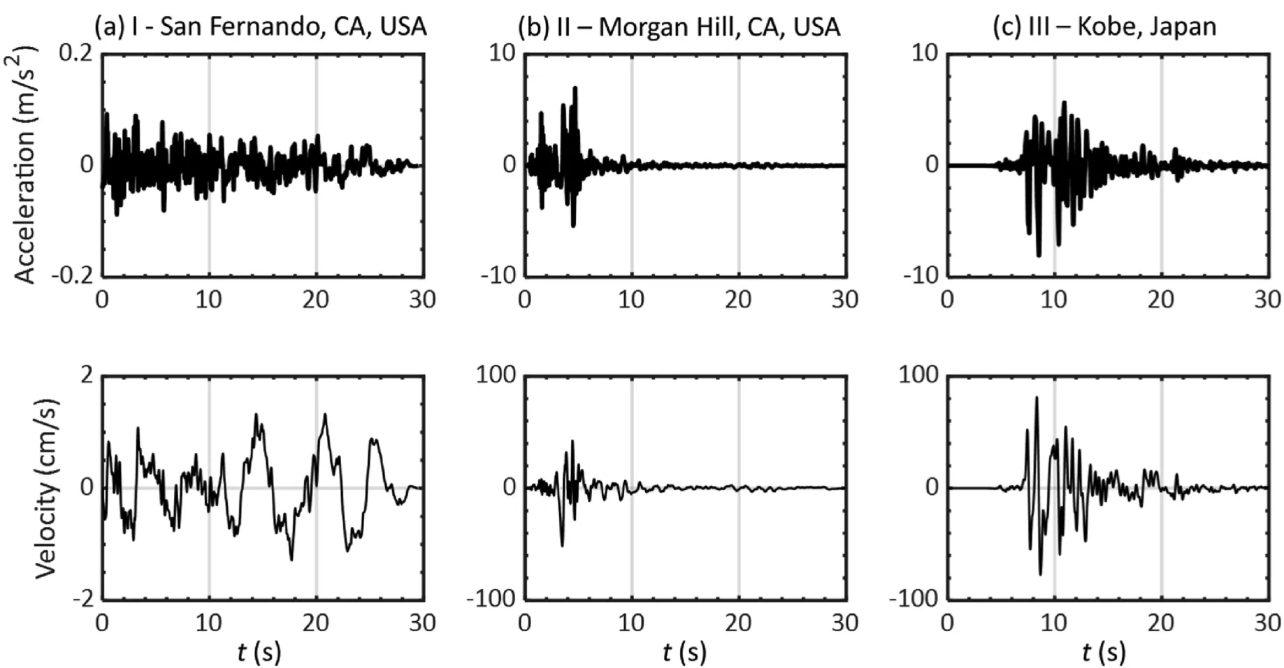
Fig.5.Plot of ground motion acceleration and velocity time histories used as input in the analysis.
Natural frequency modes of the soil column were calculated using Eq.(18) as a function of the column height (H = 10 m), unit weight (W = 18.5 kN/m3), and the linear-elastic material parameters.The value of n corresponds to the natural frequency mode.As such, setting n = 0,1, and 2 corresponds to calculating the fundamental, first and,second natural frequency mode, respectively.
The geo-static stresses in the soil column were generated using the K0-procedure assuming the at-rest lateral earth pressure (K0)equal to 0.5.The ground motion is prescribed as a time-dependent Dirichlet condition(Alsardi et al.,2021)at the base of the model to generate vertically-polarized shear (SV) waves.Also, periodic boundary conditions were specified at the lateral sides.The background computational mesh was moved after every time step to follow the input ground motion according to Alsardi et al.(2021).Similar to MPM, the Dirichlet boundary condition was applied at the base of the FEM model and the periodic boundary conditions were specified at the lateral edges of the mesh.For all the FEM models,the implicit Newmark time scheme(FEM-N)was employed with parameters set as αN=0.3025(acceleration to displacement)and δN= 0.6 (acceleration to velocity), consistent with the dissipative version of the scheme commonly used in the literature(e.g.Kontoe et al., 2008a; Pelecanos et al., 2015).
In total, four different soil column models were considered herein for verification purposes using different combinations of input motions and Young's modulus (E).Table 2 provides a summary the models'characteristics, including the elastic material properties, input ground motion, ground motion scaling factor,time step, calibrated MPM-GA parameters, and FEM-N parameters.
4.2.Verifying MPM against FEM and linear analytical solution
The goal here is to verify the implementation of the periodic boundary conditions and the MP relocation algorithm,and evaluate the effectiveness of the MPM-GA time integration scheme versus the forward MPM-EC.Towards this end, MPM results were compared against FEM and the analytically derived natural frequency harmonics.Firstly,the time and frequency domain analysis was conducted in relatively small deformation cases where cellcrossing is avoided (cases SC-1, SC-2, and SC-3 in Table 2).Secondly, the ground motion I was scaled up (case SC-4 in Table 2) in order to induce large deformations and evaluate the effect of particle relocation and cell-crossing in the results.
4.2.1.MPM verification for small deformations (no cell-crossing)
This section presents the results obtained for cases SC-1,SC-2,and SC-3 (Table 2).Case SC-1 considers the Gabor wavelet load at the fundamentalnaturalfrequencyofthesoilcolumnasinput motionand E = 1×10⁴kPa;case SC-2 and SC-3 considers ground motion I using E=1.85×10⁵kPa and E=1×10⁶kPa,respectively.In all cases,the recorded strain is small and all MPs remain within their original elements.Hence,the MP relocation algorithm is not employed.
In case SC-1,the combination of Δt and the calibrated value of ρbdamped out frequencies higher than 35 s-1,with a high bifurcation frequency of 140 s-1.Note that a low value of E was used in this case, which leads to a relatively large critical time step (Table 2).The results from case SC-1 at the top of the soil column are presented in Fig.7.It is seen that the horizontal acceleration, horizontal velocity,and horizontal displacement response of the MPMEC, MPM-GA, and the FEM using the implicit Newmark (FEM-N)time scheme are at an acceptable match as shown in the timedomain in Fig.7a, c and e, respectively.However, when plotting vertical displacement, it is observed that the MPM-EC results are contaminated with spurious oscillations (see Fig.7f).These oscillations are significantly reduced when employing the MPM-GA time scheme and are more consistent with the results of the FEM-N time scheme results.Note that this noise is not generated by cell-crossing since all MPs remain in their original elements throughout the calculation.Instead, this noise might be inherited from numerical instabilities generated as a result of spurious high frequency oscillations in the nodal solution due to performing numerical integration and stress recovery at non-ideal MP locations; this is stabilized when using numerical damping from the generalized-α time scheme (Kontoe et al., 2008a; Tran and Solowski, 2019).
Fig.8 compares the acceleration Fourier amplitude of the top and bottom MPs in the soil column for MPM-EC and MPM-GA for case SC-1.The bottom MP response is consistent with the applied wavelet ground motion.The acceleration Fourier amplitude of the bottom MP shows a single frequency component at the fundamental natural frequency of the soil column(1.116 s-1).The top MP response shows resonant behavior whereby the natural frequency component in the ground motion was amplified by an order of magnitude.In this manner, it is verified that the MPM-GA and MPM-EC schemes captured the fundamental natural frequency mode of the soil column.When using the MPM-EC scheme,the top MP also experienced different spurious frequency modes, but different from those triggered by the input wavelet ground motion.
To investigate this further,case SC-2(Table 2)used the irregular ground motion I (Table 1).In case SC-2, considering the chosen values of Δt and ρb,frequencies above 190 s-1are damped and the bifurcation frequency is 670 s-1.Similar to case SC-1,cell-crossing error is not generated in SC-2(i.e.MPs do not move across different elements).This is because the low Arias intensity from ground motion I results in small deformations.Reasonable match is seen between MPM-GA, MPM-EC, and FEM-N when considering horizontal acceleration, horizontal velocity, and horizontal displacement, as depicted in Fig.9a, c and e, respectively.However, the results using the MPM-EC scheme show progressive deviation from the FEM-N,particularly when observing the shear strain and stress in Fig.9g and h,respectively.Also,the vertical spurious oscillations were further exacerbated when using MPM-EC as shown in Fig.9b,d and f.It is observed that the MPM-GA time scheme reduces this spurious vertical noise when using an irregular cyclic input ground motion to be more consistent with the results of the FEM-N approach.To this end, the MPM-GA is seen to perform better than the MPM-EC in reducing the spurious numerical oscillations.
Using an irregular cyclic motion also offers the opportunity to plot a transfer function which enables the user to check for spurious frequency modes that may be inconsistent with the analytical solution.A transfer function, defined as the ratio of the Fourier amplitude of the “output” to the “input” ground motion, is commonly used to investigate time scheme performance in amplifying the natural frequency harmonics of a soil column(Kontoe et al., 2008a; Visone et al., 2008; Taborda, 2011).As such,the task of numerically computing a transfer function and comparing it against the analytical natural frequency is important for verifying the MPM framework.The “input” motion is the one applied at the base of the model and the“output”motion is the one obtained at the top of the soil column.This is often a required step to be conducted in linear-elasticity for verification before using more advanced constitutive models.
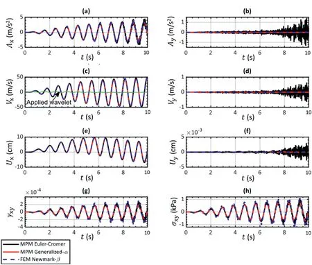
Fig.7.Comparison of MPM and FEM in the time domain when applying wavelet at resonant frequency(Case SC-1 with top MP location at(x,y)=(0.667 m,9.833 m)).Ax:horizontal acceleration; Ay: vertical acceleration; Vx: horizontal velocity; Vy: vertical velocity; Ux: horizontal displacement; Uy: vertical displacement; γxy: shear strain; σxy: shear stress.
In Fig.10a and b, the results of case SC-2 in the frequency domain using MPM-EC and MPM-GA were compared with the linear transfer function (TF) solution (Eq.(19)) assuming rigid bedrock and no material damping.
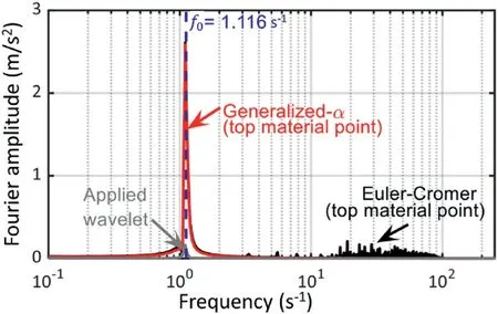
Fig.8.Fourier amplitude comparison of MPM and FEM when applying wavelet at resonant frequency (Case SC-1 with top MP location at (x, y) = (0.667 m, 9.833 m)).
It is seen that the MPM-GA captured the fundamental,first and second frequency modes(consistent with the frequency content of the applied motion ranging from 0 to 30 s-1) with relatively low amplification for high frequency noise.The MPM-EC scheme generated results that approximately captured the first few modes but it was overall highly contaminated with low and high frequencies that are not consistent with the analytical solution.From these results, it can be seen that the MPM-EC can generate numerical results that resemble reasonable results in the time domain, but does not compare reasonably with the transfer function analytical solution in the frequency domain.
For the sake of comparison, the results from case SC-3 using MPM-GA and MPM-EC in the frequency domain are also plotted in Fig.10c and d.Note that the E value of case SC-3 is higher compared to SC-2,frequencies above 265 s-1are damped,and the bifurication frequency of 1430 s-1is not reached.Similarly,the MPM-GA results show that the input motion frequencies(<30 s-1)were amplified at their respective frequency modes, whereas the MPM-EC scheme shows the spurious generation of high frequency modes.Case SC-3 presents similar match with the FEM-N in the time domain to what was observed in case SC-2.Hence,this is not presented in the paper.
4.2.2.MPM verification for large deformations (with cell crossing)
This section presents the results of case SC-4 (Table 2), which was conducted using E=1.85×10⁵kPa and ground motion I with a scaling factor equal to 128.This combination ensures large deformations of the model, which is essential to verify the implementation of the particle relocation technique and investigate the effect of particle cell-crossing on the stability of the MPM time schemes.In addition, two MPM spatial integration schemes were compared:(a)the original material point integration performed atthe mobile MPs (MP-integration) (Sulsky et al.,1994), and (b) the mixed MPM-Gauss-Point integration (Jassim, 2013) often used to reduce cell-crossing noise.In this paper, the mixed MPM-Gauss-Point integration scheme was adopted to compute the nodal internal forces,and the constitutive equation was evaluated at each individual MP to retain the history of the MP state variables.
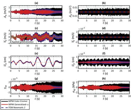
Fig.9.Comparison of MPM and FEM when applying irregular cyclic ground motion I (case SC-2 with MP location at (x, y) = (0.667 m, 9.833 m)).
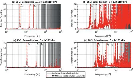
Fig.10.Transfer function obtained using MPM and comparing with the natural frequency harmonics of the soil column (cases SC-2 and SC-3).
Fig.11 shows the comparison between FEM-N, MPM-EC using MP integration, and MPM-EC using mixed MPM-Gauss-Pointintegration.The zones highlighted in gray correspond to the instants when cell-crossing occurs.Note that there is a significant deviation of the results using MPM-EC (whether MP or mixed MPM-Gauss-Point integration)from the FEM-N when cell-crossing occurs.This is particularly observed in the acceleration response in Fig.11a and b.The cumulative error resulted in spikes in the acceleration solution of MPM-EC ultimately leading to a results that is almost one order of magnitude larger than FEM-N.Additionally,the MPM-EC shows a base drift in the vertical displacement solution which manifests as an unrealistic settlement of the linear-elastic free-field column.The mixed MPM-Gauss-Point integration scheme does not show significant improvements to the spurious oscillation or the base drift seen in this case.However, the horizontal displacement solution of MPM-EC remains acceptable when comparing it to FEM-N.This highlights the significant errors that may be generated when using MPM-EC scheme for site response analysis which might be overlooked by the user of the numerical method if attention is solely given to the horizontal displacement response of the free-field column.
Moreover, the same example was repeated using the MPM-GA time integration scheme and the results are plotted in Fig.12, using the same aforementioned values of Δt,ρb,and damping ranges of case SC-2.It is observed that the acceleration response in Fig.12a using MPM-GA(either MP or mixed MPM-Gauss-Point integration)matches reasonably well with FEM-N.This ultimately generates shear strain and shear stress profiles in MPM-GA that match the results of FEM-N, as shown in Fig.12g and h, respectively.Additionally,the vertical base drift is eliminated when using MPM-GA as shown in Fig.12f.Although significantly reduced,it is seen that the some spurious oscillations still exist in MPM-GA particularly when observing the vertical accelerations in Fig.12b.Also, the mixed MPM-Gauss-Point integration is consistent with the MPintegration,and does not offer significant improvement.
Finally, case SC-4 was analyzed in the frequency domain by calculating the transfer function and comparing it to the analytical solution.It is seen that both MPM-GA and MPM-EC accurately captured the fundamental, first and second frequency modes as shown in Fig.13.However, the most important difference is that while the MPM-GA effectively damped the high frequencies noise partially due to cell crossing (only a few frequencies remain near the bifurcation limit), the high frequency content in the MPM-EC results is very significant.Consistently with the time domain results,no noticeable improvement is seen when comparing MPM-EC using MP and mixed MPM-Gauss-Point spatial integration schemes.It is important to emphasize that for the previously presented cases SC-1,SC-2,and SC-3,both spatial integration schemes(MP and mixed MPM-Gauss-Point integration) give the same results;this is expected since no cell-crossing is observed.The results presented in this section demonstrated the viability of the proposed MPM scheme to better deal with site response in small and large deformations.Consistently, all simulations presented hereafter were performed with the MPM-GA time integration scheme with the mixed MPM-Gauss-Point spatial integration.
5.Coseismic response of embankment slopes with MPM
Periodic boundary conditions have been often used in symmetric real-scale mesh-based numerical simulations.This is attributed to the simplicity in the boundary condition implementation and efficacy of the corresponding results when compared to more advanced site response treatments (Nielsen,2006).Example problems in the geotechnical literature using periodic boundary conditions include foundation structures (Kontoe et al., 2008a; Karamitros et al., 2013), tunnels (Kontoe et al.,2008b), retaining walls (Galavi et al., 2013), and slopes (Pretell et al., 2021).The purpose of this section is to show thecapabilities of the proposed MPM framework to simulate real-scale coseismic failures involving large deformations.For this, a theoretical example of a symmetric embankment slope was used.A parametric analysis is presented to explore the effect of different size embankment geometries, and highlight the implications of using different constitutive models on the runout.

Fig.11.MP versus mixed MPM-Gauss-Point integration scheme on time domain results using Euler-Cromer scheme (Case SC-4 with MP location at (x, y) = (0.667 m, 9.833 m)).
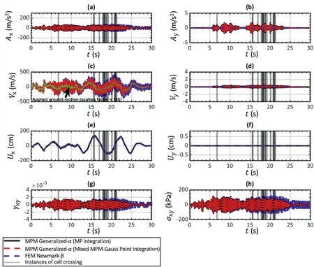
Fig.12.MP versus mixed MPM-Gauss-Point integration scheme on time domain results using generalized-α scheme (Case SC-4 with MP location at (x, y) = (0.667 m, 9.833 m)).
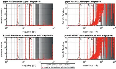
Fig.13.MP versus mixed MPM-Gauss-Point integration scheme on transfer function using generalized-α scheme (Case SC-4).
5.1.MPM numerical model
A plane-strain 35°embankment geometry overlying a 10 m soil foundation is considered for reference at small-size(Model“S”,5 m high embankment) and large-size (Model “L”,10 m high embankment).The initial spatial discretization and dimensions of both S and L models are presented in Fig.14a and b,respectively.The soil foundation at the base of the embankment is assumed linear-elastic with material parameters provided in Table 3.The unit weight(W)was assumed equal to 18.5 kN/m3for both the embankment and foundation.The MPM-GA time scheme parameters are consistent with case SC-3 in Table 2 since it has the same linear elastic parameters value.Two different constitutive soil models were adopted for the embankment.One set of simulations was performed using the linear-elastic perfectly-plastic Mohr-Coulomb (MC)model.The second set of calculations was performed with a Mohr-Coulomb model incorporating strain-softening behavior (MCSS).The second model qualitatively captures the soil strength loss suffered during cyclic loading events in a very simple way.The MCSS,also used by others(e.g.Yerro et al.,2016;Conte et al.,2019;Alsardi et al., 2021) can simulate material brittleness according to the exponential strain-softening laws presented in Eqs.(20) and(21), which shrinks the MC yield surface through the reduction of the peak friction angle and cohesion()to their residual values()at a rate controlled by the exponential fitting factor(η)and deviatoric plastic strain ().The peak strength parameters are consistent with silty sand material and were chosen to trigger failure for the considered ground motions so the capabilities of the MPM to capture large deformations can be demonstrated.The value of η was chosen to simulate a sharp drop from peak to residual conditions,consistent with brittle behavior.Note that the results of strain-softening constitutive models are mesh dependent and the value of η should be calibrated with laboratory data(e.g.Rots et al.,1985; Soga et al., 2016; Alsardi et al., 2021).This example is theoretical and a calibration is not required.All selected material parameters for the embankment are presented in Table 3.

Table 3Summary of embankment (brittle and non-brittle) and foundation material parameters used in the parametric analysis.
The calculation stages include,first,a quasi-static gravity stress initialization whereby the bottom boundary is fully fixed and the lateral sides are normally fixed.Subsequently, these boundary conditions are removed in the dynamic stage, and the ground motion is prescribed as a time-dependent Dirichlet condition (as described by Alsardi et al.(2021))at the base of the model.Periodic boundary conditions were specified at the lateral sides in the dynamic stage.The moving mesh technique was also used.The parametric analysis for 18 simulations are summarized in Table 4.To improve the comprehension of this section, the cases were labeled with the employed embankment size (S/L), constitutive model (MC/MCSS), ground motion (I/II/III), and corresponding ground motion scale factors.
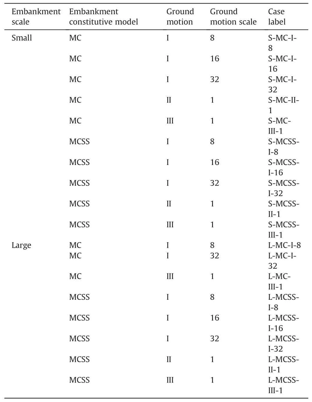
Table 4Summary of the 18 cases simulated in the example parametric analysis with details on the embankment size, constitutive model, ground motion used and ground motion scaling factor.
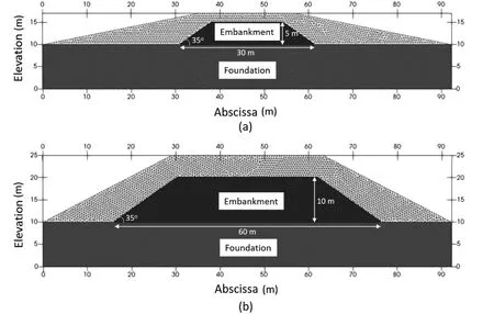
Fig.14.MPM model of the embankment overlying soil foundation.Two different size geometries adopted in this study: (a) Model S (small size), (b) Model L (large size).
5.2.Effects of ground motion arias intensity,embankment size,and constitutive model on slope runout
To the authors'experience,the horizontal movement of the MP at the crest of the embankment serves as a good approximation of the slope runout.Note that the MP initially located at the toe of the slope usually presents a more restrained movement since material located above the slope toe can override such point.To evaluate the permanent displacement from the slopes,the input ground motion at the base of the model was subtracted from the horizontal displacement time-history at the MP located at the two crests(left and right).
Fig.15 presents a comprehensive overview of the parametric analysis in terms of the horizontal runout results versus Iafor the left and right crests(Fig.15a and b,respectively).It is seen that the Iaversus runout trend is very similar for both small and large-sized embankments.However, for the same ground motion, the largescale models always generate higher runout than the small-scale counterparts; for these particular results, the scaling factor rangesfrom 2.1 to 3.4.Besides this, the permanent displacements of the embankments that behave elastic-perfectly plastic (i.e.using the MC constitutive model) are more sensitive to the input ground motion than the brittle slopes(i.e.with MCSS constitutive model).An increase by an order of magnitude of Iaresults in an increase by an order of magnitude of the runout when using the MC model.The MCSS model is seen to generate runouts that are almost independent of Ia.Additionally,the runout computed by simulations using MCSS model is always larger, ranging from one (for Ia> 2) to two(for Ia<2) orders of magnitude than the MC counterparts.These observations are consistent with the common belief that, if failure is triggered in a brittle embankment and the residual strength is very low,the runout is highly controlled by the residual strength of the mobilized material, and is less dependent on than the ground motion characteristics.Additionally, despite the ground motions are not symmetric, for the set of ground motions selected, it is quantitatively inferred that the permanent displacements are almost symmetric as the left and right crest runouts are similar for all simulations (Fig.15a and b, respectively).
Fig.16a, b and c present the initial failure mechanism, final plastic deviatoric strain,and final horizontal displacement contour plots,respectively,for the models with the highest intensity ground motion III(for reference).The initial failure mechanisms,presented in terms of localization of deviatoric strain,show that the deviatoric strain profile is similar in magnitude and shape in all cases.This similarity can be explained because the peak strength parameters used by the MCSS model at initiation are identical to the strength parameters of the MC model.Despite the similar initial failure mechanisms in all the models, larger proportion of mass is mobilized and larger final runout is observed when comparing the MCSS simulations (Fig.16c(ii) and (iv)) with their MC counterparts(Fig.16c(i)and(iii)).This is consistent with the results presented in Fig.15.Also, the initial failure mechanisms and final deformed geometries are approximately symmetric.
In order to analyze the performance of the slope in the time domain, horizontal displacement and settlement time-histories of the right crest are presented in Figs.17 and 18 for the simulations using MC and MCSS models,respectively.Note that the right side of the embankment was arbitrarily selected for discussion herein.The magnitude of runout is consistently larger than the corresponding settlement, but all time-histories, either runout or settlement,present an S-shape curve.At the beginning of the shaking, the slopes remains stable and no permanent displacement is observed.Then, a sudden increase indicates the initiation of the failure.Finally, a stable geometry is achieved and the permanent displacement becomes constant until the end of the shaking.From observing Figs.17 and 18, for a particular ground motion and constitutive model (i.e.MC or MCSS), the failure initiates at the same time independent of the model being large or small; hence,the time of failure initiation is not highly influenced by the scale of the problem.Instead,the failure initiation is much controlled by the ground motion.From these results, the constitutive model has a minor effect on the time of failure initiation.This is likely because the time of failure initiation is highly controlled by the initial strength parameters in the slope,and as discussed before,the peak strength parameters considered in the MCSS model coincide with the strength parameters of the MC model.
For the simulations with MC model(Fig.17),it is observed that when using the same ground motion scaled with different factors(e.g.I-8,I-32),the runout and settlement time-histories are scaled.However, the runout and settlement time-history are not consistently scaled according to the scaling factor of the ground motion.To this end, the use of totally different ground motions (e.g.III-1)completely changes the evolution of permanent displacements.Also, consistently with previous observations (Figs.15 and 16)when considering the MCSS model for the same scale,Fig.18 shows that the crest final runouts and settlements are roughly constant for all the simulations.This parametric analysis shows the importance of geometry and material behavior characterization.The selection of an adequate constitutive model capable of reproducing the key features of the material is essential to capture the runout and settlement trends.These modeling decisions can greatly determine the displacement trends observed at large deformations.

Fig.15.Horizontal permanent displacements of the crest obtained from 18 ground motions using the MPM model plotted against the arias intensity of the used ground motion.(a) Left crest, (b) right crest.
5.3.Comparing MPM numerical results with the newmark method
The purpose of this subsection is to compare the performance of the MPM model with the well-known Newmark sliding block solution(Newmark,1965).The value of fundamental natural period of the MPM embankments (T0= 1/f0) was calculated as an approximation to guide whether the models can be characterized as“rigid”or“flexible”.The value of f0was calculated using Eq.(18),assuming H equals to the height of the embankment and fundamental mode (n = 0).This approximation was pragmatically adopted for slopes in geotechnical earthquake engineering(e.g.Cho et al.,2022).It is seen that T0is equal to 0.04 s and 0.09 s for small and large-sized embankments, respectively.For this study, a threshold value of T0= 0.2 s was adopted as the limit of rigid behavior, consistent with Fotopoulou and Pitilakis (2015).Thus,both slope geometries analyzed herein can be characterized as rigid, which is consistent with Newmark's assumptions.As such,the numerical solution of the MPM was compared to the Newmark rigid sliding block solution, obtained using Slammer software(Jibson et al., 2013).
To determine yield pseudostatic coefficient (ky), for use in Newmark rigid sliding block solution, pseudostatic analyses using the Spencer (1967) limit equilibrium method was performed to identify the failure surface with yield pseudostatic coefficient kythat provides a factor of safety equal to one.The limit equilibrium software package by GeoStudio (GEO-SLOPE, 2012) was used whereby a pseudostatic analysis was conducted and kywas varied incrementally by 0.01 until a factor of safety of one was reached for each geometry.The resulting value of kyis 0.21 and 0.11 for model S(small-sized) and L (large-sized), respectively.Even though baseline corrected, the ground motions time-histories are not symmetric in the left and right directions.Due to this, the choice of using Newmark-forward (positive ky) and Newmark-inverse(negative ky) methods would generate different results.It is postulated to compare Newmark-forward method with the left-toright deformation of the right crest in the MPM model, and Newmark-inverse method with the right-to-left deformation of the left crest in the MPM model.Ground motion III that has the highest Arias intensity is considered for comparison.The evolution of the horizontal permanent displacements using the MPM models and Newmark method are presented in Fig.19a and b for the left and right crest points,respectively.The order of magnitude of Newmark permanent displacements is consistent with the results from cases employing the MC model (i.e.S-MC-III-1 and L-MC-III-1).The Newmark results are slightly lower than the MPM results.This can be explained because the ground motion is amplified in the numerical model when it passes through the linear-elastic soil foundation, while the Newmark approach does not account for such amplification (equivalent to a fully rigid foundation).The Newmark-forward generated results that are higher than the Newmark-inverse.This is consistently captured in the MPM with the right crest having larger runout than the left crest.It is noted that, if a brittle material behavior is assumed, e.g.using the MCSS model,the numerical results are larger by a factor ranging from 6 to 10 times (i.e.approximately one order of magnitude) than the Newmark results.Additionally, in this case, the MCSS model predicts a slightly earlier point of failure initiation than Newmark method.This further highlights the importance of the constitutive model selection when simulating coseismic landslides and the limitations of the Newmark rigid sliding block solution to predict permanent displacements in relatively complex sites.
6.Conclusions
This paper presents the MPM as a capable tool to simulate coseismic site response and embankment instabilities using periodic boundary conditions.A particle relocation technique at the periodic boundaries was proposed to ensure that the material points always remain within the computational mesh.Additionally,for the first time,the explicit generalized-α time scheme was used for earthquake engineering applications in MPM.The developed MPM framework was verified at element-level against corresponding FEM simulations and the linear analytical site response approach in the time domain.Additionally,analysis of the transfer function in the frequency domain highlights the ability of the MPM framework in capturing the natural frequency harmonics of a soil column.The high frequency oscillations are appropriately dampedto filter out the noise,and this effect is observed in the time-domain and frequency-domain.

Fig.16.Contour plots of the embankments:(a)Plastic deviatoric strain profile at failure initiation;(b)Final plastic deviatoric strain profile;(c)Final horizontal displacement.Results shown used ground motion III which caused the largest deformations with the corresponding cases: (i) S-MC-III-1; (ii) S-MCSS-III-1; (iii) L-MC-III-1; (iv) L-MCSS-III-1.

Fig.17.Horizontal permanent displacement time-histories of the right crest obtained using the Mohr-Coulomb (MC) constitutive model.

Fig.18.Horizontal permanent displacement time-histories of the right crest obtained using the Mohr-Coulomb with Strain-Softening (MCSS) constitutive model.
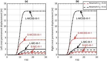
Fig.19.Horizontal permanent displacements of the crests compared with Newmark solutions: (a) Left crest compared with Newmark-inverse (negative ky), and (b) Right crest compared with Newmark-forward (positive ky).
A parametric analysis was provided to demonstrate the new MPM framework to simulate real-scale coseismic failures and the performance of a theoretical embankment was investigated.The effects of ground motion Arias intensity, embankment size(doubling the size), and constitutive models (i.e.MC and MCSS)were considered.The larger the model size, the higher the crest runout and settlement for the same ground motion.Brittle embankments (using MCSS) resulted in larger slope mobility compared to the models using MC model.When considering MC model, the crest runout and settlement increases with Ia.Contrarily, when brittle embankment material is considered, the runout and settlement is relatively constant for the different ground motions considered, indicating that the runout of brittle embankments is highly controlled by the residual strength of the mobilized material, and is less dependent on than the ground motion characteristics.Similar failure mechanisms are observed in all cases.
Finally, the Newmark rigid sliding block solution (Newmark,1965) was compared to the MPM embankment simulations.The Newmark-forward (positive ky) and Newmark-inverse (negative ky) are seen to be consistent with the right and left crest, respectively, when using MC model.This is consistent with the fact that the considered embankments have a low natural period (<0.2 s).However, the assumption of brittle embankment behavior using MCSS model leads to runout results that one order of magnitude larger.This paper highlights the importance of the geometry and the selection of appropriate constitutive models when simulating coseismic site response,failure,and post-failure behavior of slopes.Future work includes the use of advanced constitutive models especially developed for geotechnical earthquake engineering applications for a more accurate estimation of soil behavior under cyclic loading.
Declaration of competing interest
The authors declare that they have no known competing financial interests or personal relationships that could have appeared to influence the work reported in this paper.
Acknowledgments
This research was partially funded by National Science Foundation (NSF) (Grant No.CMMI-2211002).The first author acknowledges funding from Department of Civil and Environmental Engineering at Virginia Tech for his graduate studies.The first author also thanks the Los Alamos National Laboratory(LANL)and the Earthquake Engineering Research Institute(EERI)for financially supporting the author to attend the 12th National Conference on Earthquake Engineering, where the author discussed this work with the research community.However, any opinions, findings,conclusions, or recommendations expressed in this material are those of the authors and do not necessarily reflect the views of NSF or others acknowledged.
List of symbols
 Journal of Rock Mechanics and Geotechnical Engineering2023年3期
- Journal of Rock Mechanics and Geotechnical Engineering的其它文章
- Development of mathematically motivated hybrid soft computing models for improved predictions of ultimate bearing capacity of shallow foundations
- A post-peak dilatancy model for soft rock and its application in deep tunnel excavation
- Numerical simulation of fatigue crack propagation in heterogeneous geomaterials under varied loads using displacement discontinuity method
- Combined load bearing capacity of rigid piles embedded in a crossanisotropic clay deposit using 3D finite element lower bound
- Long-term decay of the water pressure in the osmotic tensiometer
- Predicting and validating the load-settlement behavior of large-scale geosynthetic-reinforced soil abutments using hybrid intelligent modeling
