Lift performance enhancement for flapping airfoils by considering surging motion
To WU, Bifeng SONG,b, Wenping SONG,c, Wenqing YANG,b,c,*,Dong XUE, Zhonghu HAN
a School of Aeronautics, Northwestern Polytechnical University, Xi’an 710072, China
b Research & Development Institute of Northwestern Polytechnical University in Shenzhen, Shenzhen 518057, China
c Yangtze River Delta Research Institute of Northwestern Polytechnical University, Taicang 215400, China
KEYWORDS Aerodynamics;Flapping airfoils;Surging motion;Trajectory optimization;Unsteady flow
Abstract The flapping motion has a great impact on the aerodynamic performance of flapping wings.In this paper,a surging motion is added to an airfoil performing pitching-plunging combined motion to figure out how it influences the lift performance and flow pattern of flapping airfoils.Firstly, the numerical methods are validated by a NACA0012 airfoil pitching case and a NACA0012 airfoil plunging case.Then,the E377m airfoil which has typical geometric characteristics of the bird-like airfoil is selected as the calculation model to study how phase differences φ1 between surging motion and plunging motion affect the aerodynamic performance of flapping airfoils. The results show that the airfoil with surging motion has comprehensively better lift performance and thrust performance than the airfoil without surging motion when 15°<φ1 <90°. It is demonstrated that surging motion has a powerful ability to improve the aerodynamic performance of flapping airfoil by adjusting φ1.Finally,to further explore how flapping airfoil improves lift performance by considering surging motion,the flapping motions of E377m airfoil with the highest lift coefficient and lift efficiency are obtained through trajectory optimization. The surging motion is removed in the highest lift case and highest lift efficiency case respectively,and the mechanism that surging motion adjusts the aerodynamic force is analyzed in detail by comparing the vortex structure and kinematic parameters.The results of this paper help reveal the aerodynamic mechanism of bird flight and guide the design of Flapping wing Micro Air Vehicles (FMAV).
1. Introduction
The macrostructures and microstructures, shapes, and movements of living things in nature are results of hundreds of millions of years of natural selection,and many of their functions are far beyond human imagination. Among them, birds and other flying creatures have developed extraordinary aerial flight capabilities after a long period of environmental adaptation to obtain food, escape from predators, and pursue their mates.The flapping wings are the direct source of aerodynamic force for birds.The flapping motions are crucial to the high lift and high-efficiency flight of birds. Studying the aerodynamic effects of different flapping motions is of great significance to reveal the flight mechanism of birds and to guide the design of Flapping wing Micro Air Vehicles (FMAV).
Typical flapping motion of a bird includes plunging, pitching, surging, and folding. Among them, plunging motion and pitching motion are the most important movements for birds to generate lift and thrust.At present,a large number of studies, including kinematic, morphology, and deformation on aerodynamic performance of pitching and plunging airfoil,have been carried out.Generally,the airfoil is able to generate thrust with suitable plunging motion.Besides,the combination of plunging motion and pitching motion can provide large thrust and propulsion efficiency for flapping airfoil.The owl-inspired plunging motion and pitching motion have obvious advantages in lift generation and energy-saving,compared with conventional sinusoidal motion.A time-asymmetry plunging motion trajectory inspired by natural flyers shows a noticeable increase in thrust and lift at a relatively small downstroke time ratio.Folding and surging motions have gradually attracted people’s attention due to their great potential in regulating aerodynamic performance. Bahlman et al.and Wang et al.studied the flapping of bat wings and found that dynamically extending wingspan during downstroke and folding wingspan during upstroke considerably contributed to the enhancement of lift and lift efficiency.Crandell and Tobalskeand Chang et al.studied the flapping of bird wings and came to similar conclusions. Besides, Chang et al.measured the kinematics of wing flexion and extension in common pigeons and developed a biohybrid morphing wing with real feathers.Their flight tests demonstrate that dynamically folding of wings can well improve the maneuverability of flying vehicles.
The surging motion is a motion that airfoil translates in horizontal direction (in-line motion), which has been noted in unrestrained swimming turtles,flying pegions,and free-flying barn owl.Licht et al.experimentally investigated NACA0012 airfoil with a turtle-inspired surging motion and found that a powerful downstroke together with a properly backward surging motion can provide substantial thrust and high efficiency. Bansmer and Radespielnumerically studied forward surging and backward surging motion on the aerodynamic performance of a birdlike flapping airfoil SG04. It was indicated a forward surging motion during flapping downstroke increases both propulsive efficiency and thrust for flying birds, which differs greatly from that of underwater animals.Licht et al.and Bansmer and Radespielrespectively demonstrated that surging motion plays an important role in thrust performance improvement of swimming and flying creatures. Afterward, more kinematic parameters of surging motion have been comprehensively studied.Esfahani et al.numerically investigated different motion trajectories on fluid structures of NACA0012 airfoil.They concluded that the elliptical motion trajectory and fish-like motion pattern significantly enhance the propulsive efficiency of flapping airfoils.Izraelevitz and Triantafyllouexperimentally studied NACA0013 flapping airfoil and found that surging motion can be a powerful mean to either substantially augment the mean lift, or reduce oscillatory lift. Wu et al.and Wang et al.researched various types of motion trajectories on the power extraction performance of NACA0015 flapping airfoil,and they pointed out the efficiency of power extraction can be improved when properly surging motion is added for flapping airfoil.Further,Wu et al.performed the numerical simulations on a NACA0012 airfoil,and found that the figure-ofeight motion trajectory has a promotion for the thrust and propulsive efficiency,the lift is also improved when the relative surging frequency k is an odd number. Although there have been some conclusions on the aerodynamic effects of surging motion on flapping airfoils, it should be pointed out that almost all studies have been carried out on symmetrical airfoils, and more attention has been paid to the impact of surging motion on thrust performance. There is not enough focus on the influence of surging motion on aerodynamic performance of unsymmetrical airfoils. Especially, how surging motion affects lift performance and flow pattern of unsymmetrical airfoils has not yet been carried out.
In this paper, an unsymmetrical airfoil that is quite similar to the inner wing profile of birds is adopted to investigate the effect of surging motion on aerodynamic performance of flapping airfoil by numerical simulation, especially lift performance and flow pattern are concerned. Initially, the CFD solver is validated by two numerical cases. Then, the typical surging motion parameter φis studied, and how it influences time-averaged lift performance, thrust performance,and aerodynamic power of flapping airfoils are addressed. Finally, to further explore how the flapping airfoil improves lift performance by adjusting surging motion, the flapping motion that can provide maximum lift, and flapping motion that can provide maximum lift efficiency are obtained respectively by surrogate-based optimization. The lift performances of the optimal flapping motion that retains and removes surging motion are compared. The mechanisms of high lift and high lift efficiency by adjusting φare analyzed in detail.
2. Methodology
2.1. Geometric model and flapping motion
The E377m airfoil, shown in Fig. 1, is adopted as the computational model in this paper.The E377m airfoil has a relatively large leading-edge radius, large airfoil camber, and thin trailing edge, which are quite similar to the profile of bird wings.
The kinematic of flapping airfoil combines a plunging motion in the vertical direction y(t), a pitching motion about the quarter chord point α(t), and a surging motion in the horizontal direction x(t). In this study, we focus our attention on the flight of birds,of which the vertical motion and horizontal motion have the same flapping frequency. So we only use one flapping frequency to model the plunging motion, pitching motion, and surging motion. The kinematic equations of different motions are defined as:

Fig. 1 E377m airfoil.
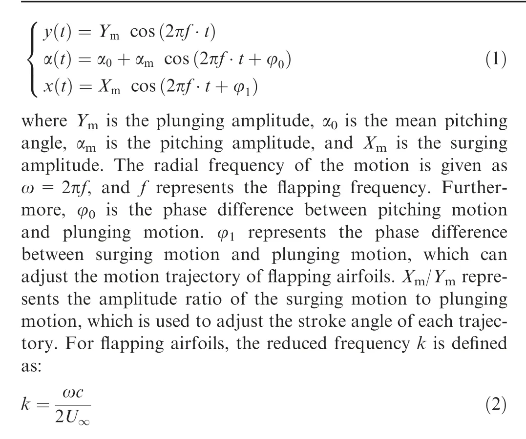
which is usually used to describe unsteady motion.Detailed values of kinematic parameters investigated in this study are listed in Table 1. Correspondingly, the schematic diagrams of motion trajectories with different combinations of φand X/Yare shown in Fig. 2.
2.2. Performance
The time-averaged lift coefficient C, thrust coefficient C,and power coefficient Care adopted to evaluate the aerodynamic performance of flapping airfoil. They are defined as follows:
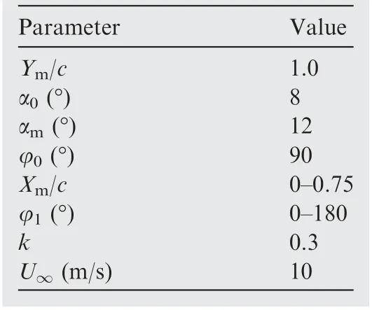
Table 1 Values of kinematic parameters for flapping motion.
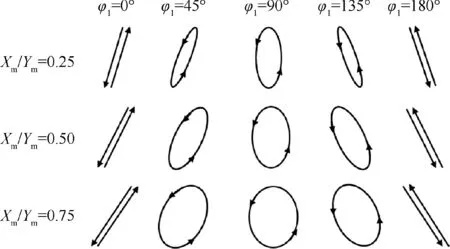
Fig. 2 Motion trajectories under different φ1 and Xm/Ym.
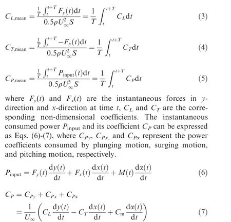
Lift efficiency and propulsive efficiency can be defined as follows:

The effective angle of attack αand the effective freestream velocity u, which are highly correlated to flow pattern, are introduced to analyze the flapping process of the airfoil. As shown in Fig.3,uis the resultant velocity that the freestream moves relative to the airfoil.αis the angle between the chord line of airfoil and the resultant flow velocity.αand ucan be expressed as Eqs. (10) and (11).

2.3. Numerical methods and solver validation
An in-house CFD solver, called ‘‘PMNS2D”,is used in this work. The preconditioned Unsteady Reynolds Averaged Navier-Stokes (URANS) equations are solved based on a Finite Volume Method (FVM) within the framework of an efficient Full Approximation Storage(FAS)multigrid method.The space discretization is a cell-centered finite volume method using central difference,with nearly second-order accuracy on smooth structured grid. A dual time-stepping method is adopted for time marching and the LU-SGS scheme is implemented to accelerate the convergence for the inner iteration of pseudo-time stepping. SA turbulence model is adopted in this study to close the URANS equations.
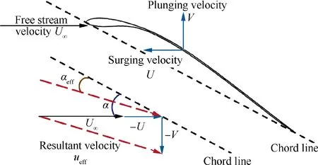
Fig. 3 Effective angle of attack αeff and effective freestream velocity ueff.
Two test cases are chosen to evaluate the accuracy and reliability of the solver- ‘‘PMNS2D” for low Reynolds number unsteady flow simulation.One case is a NACA0012 airfoil performing pure pitching motion, and the other case is a NACA0012 airfoil performing pure plunging motion.
2.3.1. NACA0012 airfoil pitching case
The first case tested is a NACA0012 airfoil with sinusoidal pitching oscillation. The experiment was conducted by Lee and Gerontakos,which was performed in the 0.9 m×1.2 m×2.7 m low-speed, suction-type wind tunnel in the Aerodynamics Laboratory at McGill University. The flow conditions are listed as follows: freestream velocity U=14 m/s, the chord-based Reynolds number Re=1.35×10. The kinematic parameters of pitching motion are: α=10°, α=15°, and the reduced frequency k=0.1. The distribution of the computational mesh in the streamwise direction and wall-normal direction is 449×169,the first grid layer spacing is 1.0×10c, and yis less than 1.0.The hysteresis curve of the lift coefficient of the numerical simulation is depicted in Fig. 4. The overall trends of the instantaneous lift coefficient Cfor the present simulation are consistent with Lee’s experimental data and Li’s numerical results. Hence, it is convincing to use the present solver to predict the unsteady lift performance of flapping airfoils in this study.
2.3.2. NACA0012 airfoil plunging case
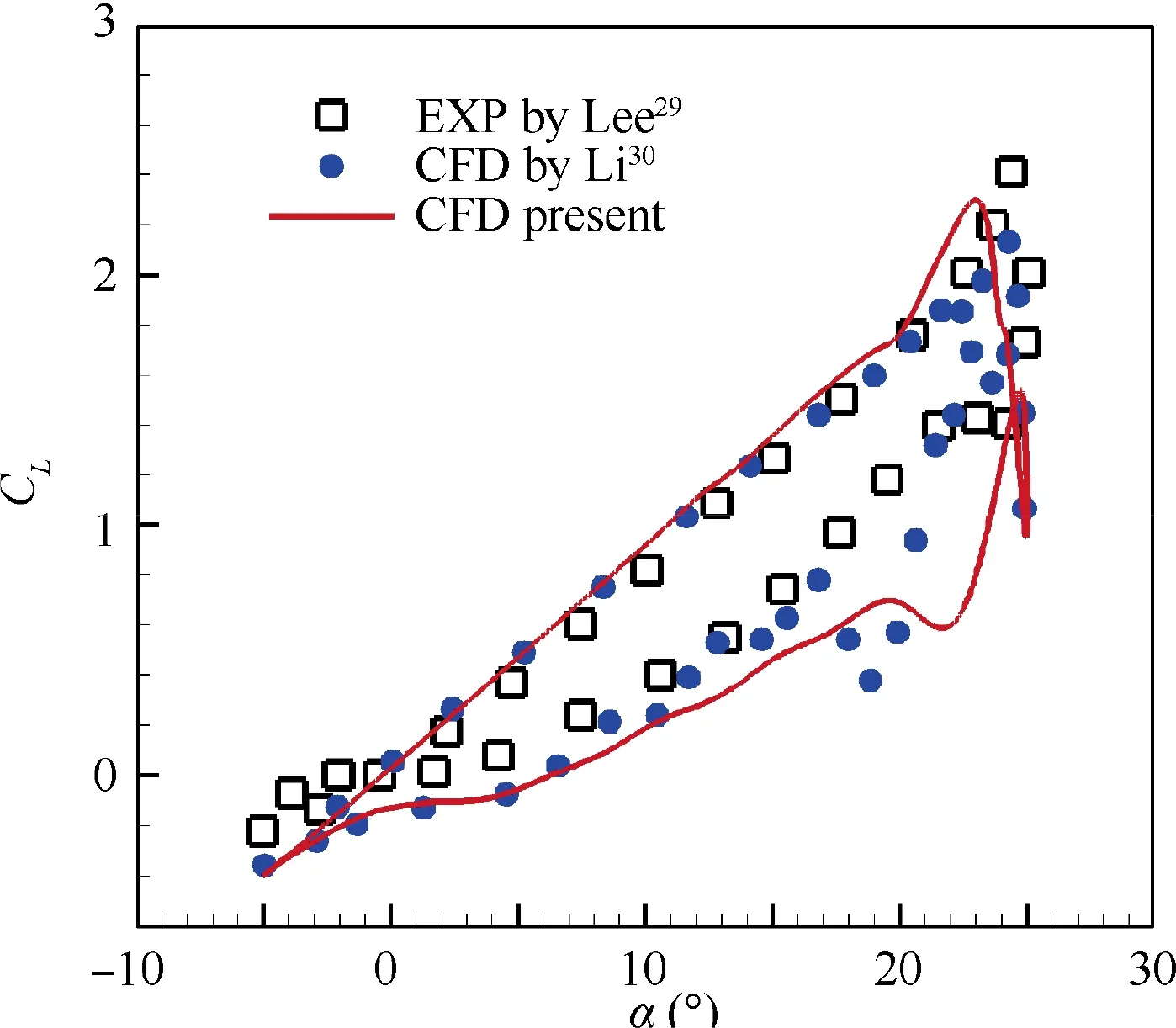
Fig. 4 Comparison of lift coefficient loops between experiment and CFD simulations for NACA0012 airfoil.
The second case tested is a NACA0012 airfoil with sinusoidal plunging oscillation.The experiment was conducted by Heathcote et al.The flow conditions are listed as follows: freestream velocity U=3 m/s, the chord-based Reynolds number Re=2.0×10.The kinematic parameter of plunging motion is Y=0.175c, and k is in the range of 0.5 to 4. The distribution of the computational mesh in the streamwise direction and wall-normal direction is 449×145,the first grid layer spacing is 4.0×10c, and yis less than 1.0. Fig. 5 shows the comparison of C, C, and ƞfor present CFD simulation, Young’s CFD simulation,and experimental measurement. Our calculation results show similar trends compared with Young’s CFD simulation and experimental data.Overall,it is reliable to use our CFD solver‘‘PMNS2D”to estimate thrust performance and power consumption for the present study.
2.4. Convergence study of grid size and time resolution
In this part, different grid sizes and time steps are adopted to choose a suitable mesh scale and time step for good accuracy of numerical simulation. The flow conditions are freestream velocity U=10 m/s, Reynolds number Re=5.6×10,which are quite similar to that of a pigeon’s flight during cruising. The kinematic parameters of flapping motion have been shown in Table 1, with X=0 adopted in this section.
2.4.1. Grid resolution study
A convergence study of grid size is carried out over three meshes. Detailed kinematic parameters employed for different grid sizes are presented in Table 2,and a medium-level O-mesh for E377m airfoil is shown in Fig. 6.
Instantaneous lift coefficient Cand thrust coefficient Cfor different grid sizes are shown in Fig.7.The computational results from the medium grid deviate slightly from those of the dense grid, indicating that grid independence has been achieved between medium grid and dense grid. Therefore,the medium grid with a size of 413×133 is chosen for the following simulation.
2.4.2. Time resolution study
The time step sensitivity test is carried out over the mediummesh of E377m airfoil.Unsteady simulation is performed with a flapping cycle divided into 144,288,and 432-time steps.Each case is calculated for 10 cycles to ensure convergence of results.Instantaneous lift coefficient and thrust coefficient during the tenth cycle for different time steps are shown in Fig. 8. Force coefficients show little difference among three different time steps. Good time resolution can be achieved with 288-time steps in a flapping cycle. Hence, 288-time steps during a cycle are adopted to carry out all the subsequent simulations.
3. Results and discussion
3.1. Effects of phase difference between surging motion and plunging motion

Fig. 5 Comparison of aerodynamic coefficients between experiment and CFD simulations for NACA0012 airfoil.

Table 2 Parameters of different grids employed for E377m airfoil.
The influences of the phase difference between surging motion and plunging motion on the aerodynamic performance of the E377 airfoil are shown in Fig. 9. The ratios of X/Yconsidered in the study are 0, 0.25, 0.375, 0.5, 0.625 and 0.75. The surging motion is removed when X/Y=0. When ratios of X/Yremain constant, Cinitially increases and then decreases with increasing φ. The peak values of Care obtained when φ=45°. Both Cand Cgradually decrease with increasing φ. Besides, ηis improved continuously while ηis decreased with the increase of φ. Compared with the airfoil without surging motion,the surging airfoil can achieve higher C, C, ηand ηwhen 15°<φ<90°. Moreover, the values of C, C, ηand ηgradually increase with the increase of X/Y. From these results, we can conclude that surging motion has a powerful ability to improve the aerodynamic performance of flapping airfoil by adjusting φ.
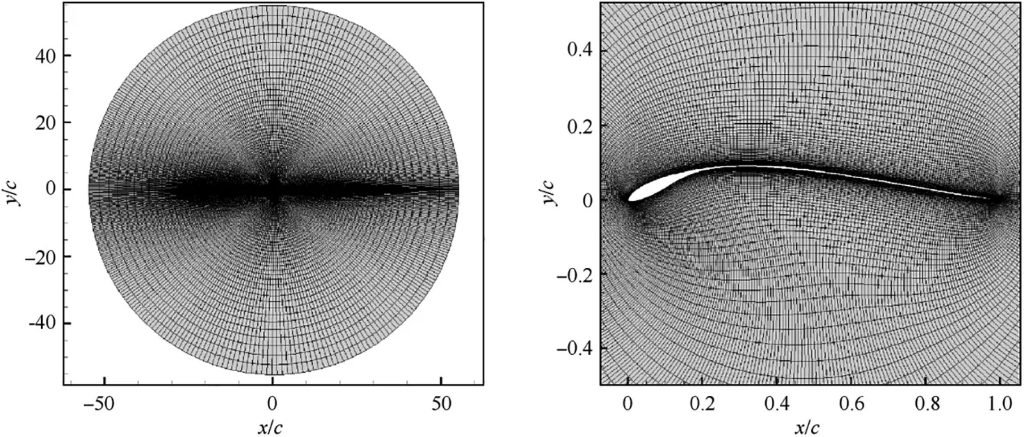
Fig. 6 Medium level O-mesh for E377m airfoil.
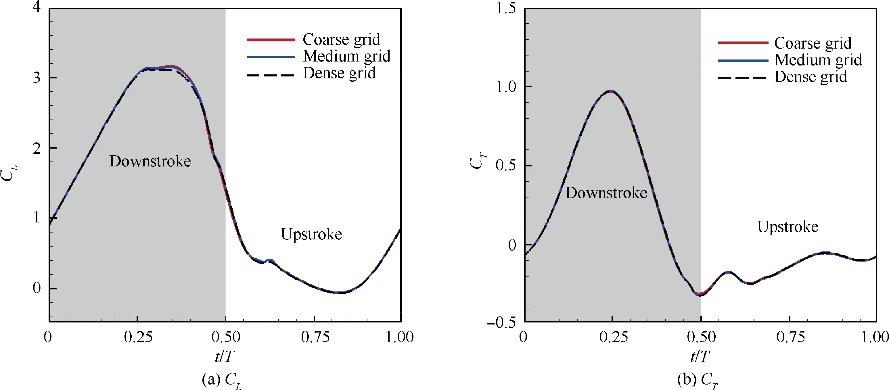
Fig. 7 Instantaneous lift coefficient and thrust coefficient for different grid sizes.
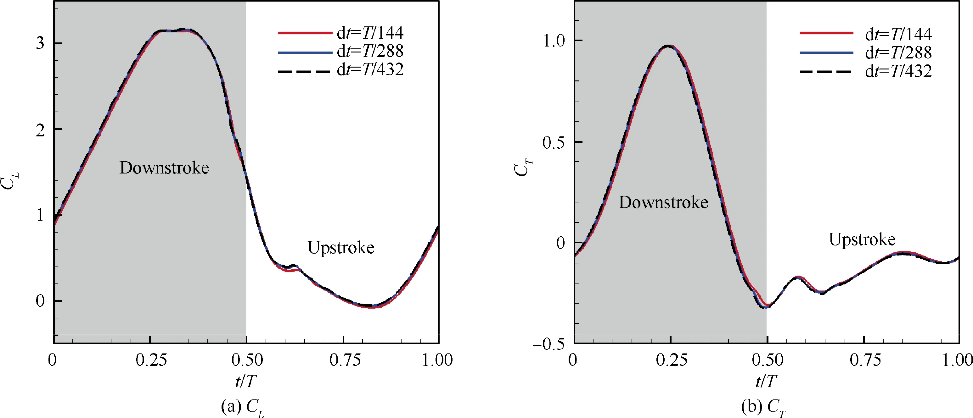
Fig. 8 Instantaneous lift coefficient and thrust coefficient for different time steps.
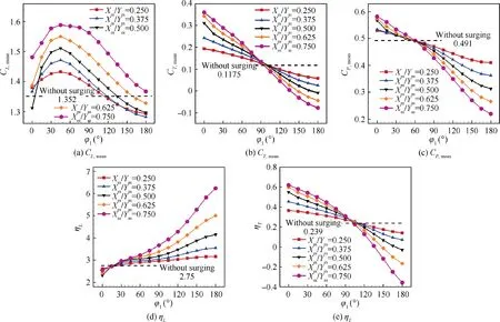
Fig. 9 Effects of φ1 on CL,mean, CT,mean, Cp,mean, ƞL and ƞT under different Xm/Ym.
The variations of Cunder different X/Yshow a similar trend, as shown in Fig. 9(a). Thus, only X/Y=0.5 is chosen to analyze the effects of φon the flow pattern and the instantaneous lift coefficient C.
The distributions of the vorticity and pressure for E377m airfoil during a flapping cycle under different φare presented in Fig.10.During the downstroke,the upper surface of E377m airfoil has experienced the formation of LEV, the growth of LEV, the formation of secondary vortex, the growth of secondary vortex and lift-up of LEV, and the shedding of LEV under different φ, except for the case of φ=0°. When φ=0°, only a trailing edge vortex is formed and gradually grows in size towards the front edge on the upper surface of airfoil during downstroke. When φchanges from 45° to 180°, stronger LEV is formed on the upper surface of the airfoil with φincreasing at middle of the downstroke(t=0.25 T). To figure out how φaffects the evolution of LEV, the time history of αunder different φis depicted in Fig. 11. Referring to Ref. 33,34, the value of αhas a significant impact on the evolution of the LEV.The rapidly increasing αwill promote the formation and growth of the LEV.Meanwhile, an excessive value of αwill weaken the stability of the LEV and promote it to shed off. During the early stage of downstroke, higher increase rate and relatively larger amplitude of αis achieved when φchanges from 45° to 180°. Therefore, it’s observed that the LEV forms earlier, grows faster, and falls off earlier with the increase of φduring downstroke. As for φ=0°, there is only a short increasing time for α, making its amplitude quite small, so there is no obvious LEV formed on suction surface of E377m airfoil.
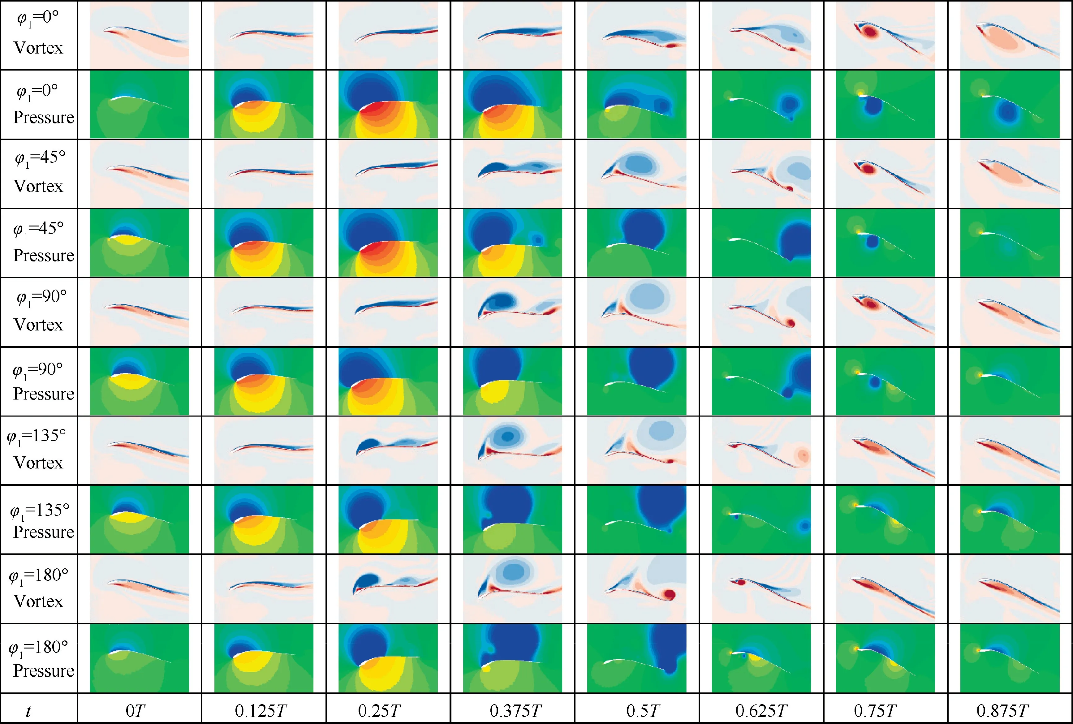
Fig. 10 Vortex evolution process and pressure distribution on E377m airfoil during a flapping cycle under different φ1.
The influences of φon the formation of LEV are further quantified by the circulation of LEV (Γ). As shown in:
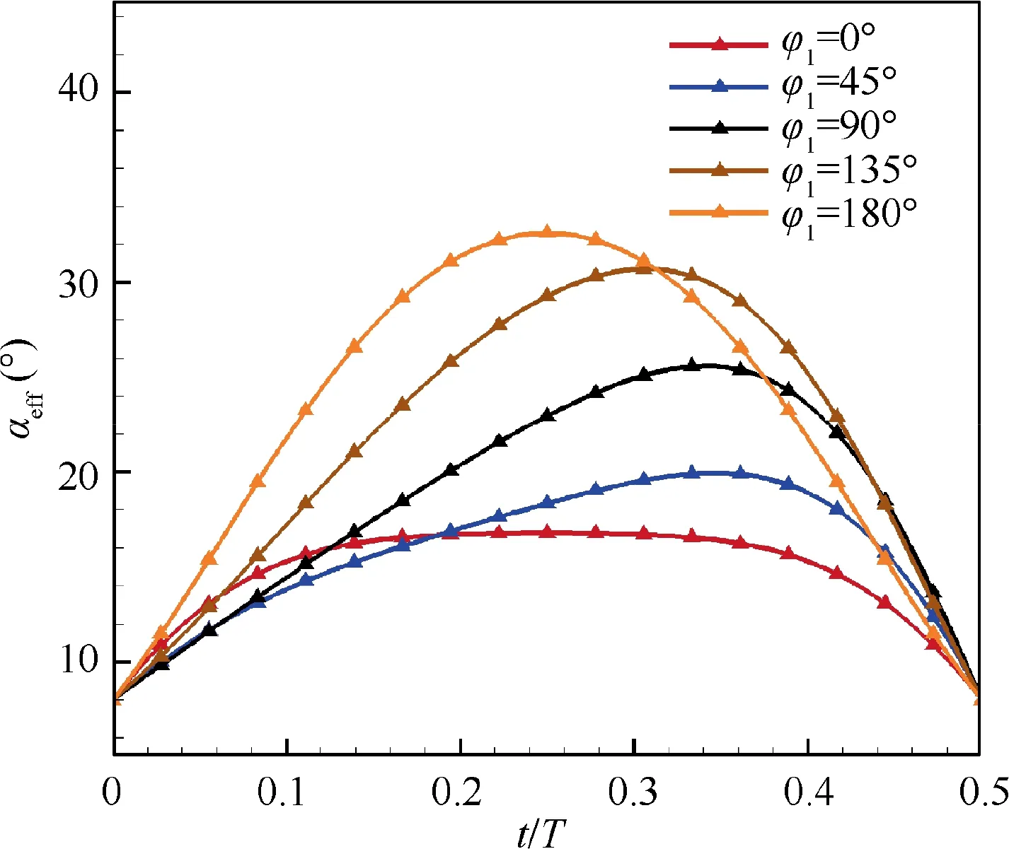
Fig. 11 Change of effective angle of attack αeff under different φ1.

ωis the vorticity, and Sis the region of LEV. In this study, the boundary of LEV is identified by Q-criterion with Q=1.0. The time history of non-dimensional circulation of the LEV (Γ/cU)is shown in Fig. 12.As expected,stronger LEV is formed at larger φ, thus the LEV circulation will increase with φgrowing up. The growth process of LEV circulation at different φis quite similar. It first grows rapidly and then slowly. The change of growth rate is related to the appearance of the secondary vortex structure. As shown in Fig. 13, a secondary vortex shows up between the LEV and the leading-edge shear layer at 0.33 T. With the growth of the secondary vortex(see 0.33 T to 0.44 T), the momentum exchange between the leading edge shear layer and the LEV is gradually blocked, which makes LEV circulations grow slowly and eventually decay.
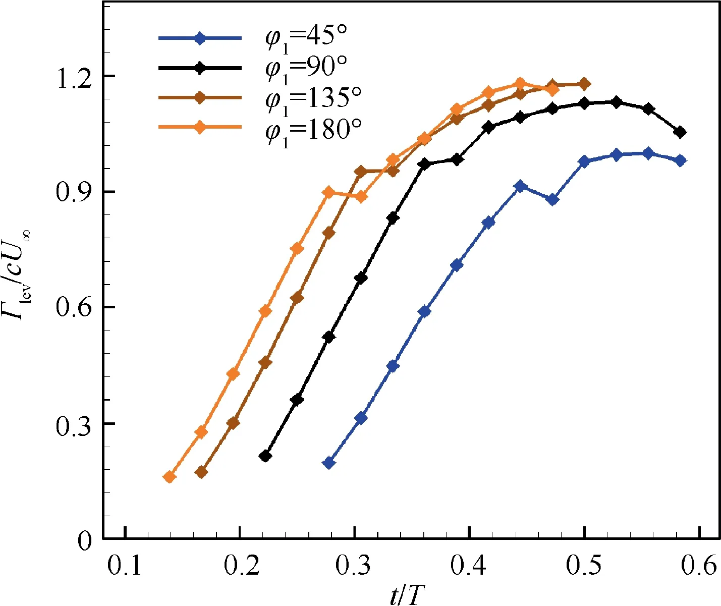
Fig. 12 Evolution of non-dimensional circulation for LEV.

Fig. 13 Vortex evolution process on the suction surface of E377m when φ1=90° (ωz*=ωzc/U∞).
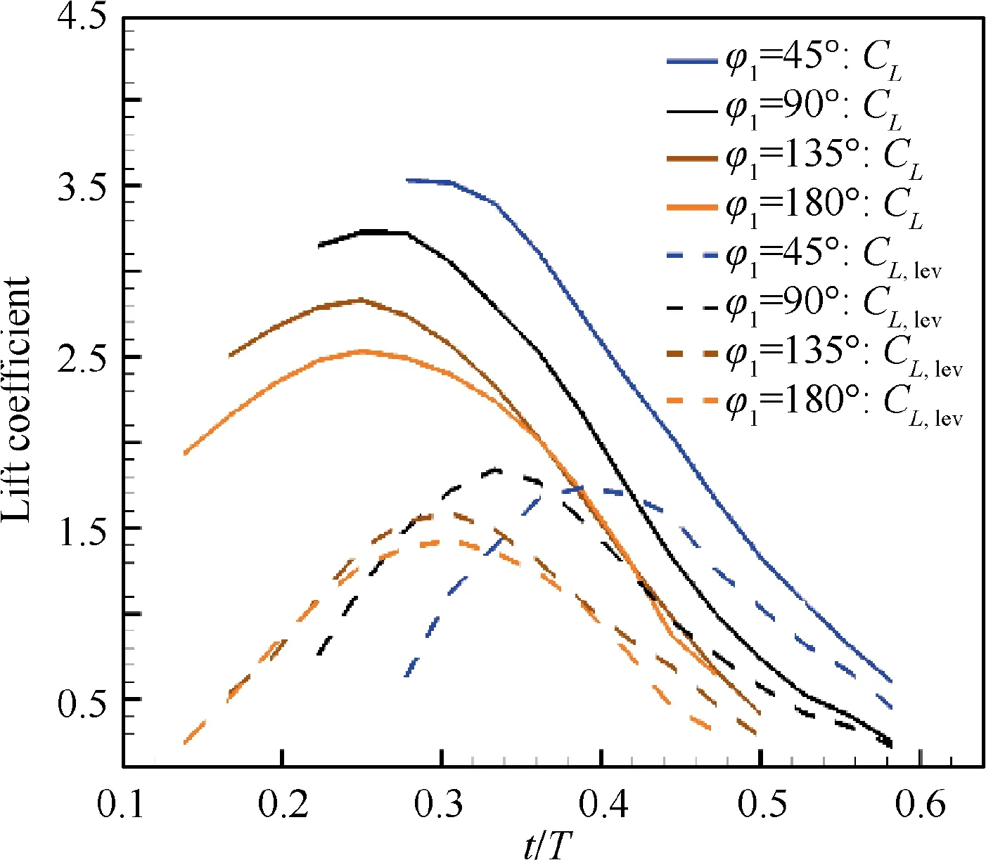
Fig. 14 Total lift coefficient(CL) and LEV contributed lift coefficient(CL,lev) during the evolution period of LEV.
The attached LEV has been proved to be very important for improving the lift performance of the flapping wing. In general, a larger attached LEV can induce a much lower pressure region on the upper surface of the airfoil, which helps to increase the lift. To better understand the lift enhancement mechanism of the LEV, the lift contributed directly by the LEV (C) is calculated. Cis given as follows:R|C|ds, which can represent the contribution of the LEV to the total lift.Both total lift coefficient(C) and the LEV contributed lift coefficient(C) during the evolution period of LEV are shown in Fig.14. It is found that the trends of Cand Care quite different at relatively small φ. When φequals 45°and 90°,Ccontinues to decrease during the growth period of C. This indicates that the contribution of the leading-edge vortex to the lift does not dominate the variation of total lift.When φequals 135°and 180°,Cand Chave a similar change trend, meaning that the contribution of LEV to lift generation is enhanced. The distributions of the vorticity,velocity,and pressure for E377m airfoil at middle of downstroke(0.25 T)are shown in Fig.15.When φis less than 90°,we can observe that it is the high-speed movement of fluid on the upper surface of the airfoil, rather than the leading edge vortex structure, which leads to a large low-pressure area on the suction surface.When φis greater than 90°,the low pressure induced by the LEV dominates the pressure distribution on the airfoil suction surface, which contributes a lot to lift enhancement. These results indicate that φcan significantly change the flow pattern on the upper surface of the airfoil,thereby adjusting the lift.
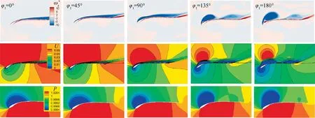
Fig. 15 Distributions of the non-dimensional vorticity(ωz*), velocity(U), and pressure(P) for E377m airfoil at middle of downstroke(0.25T).
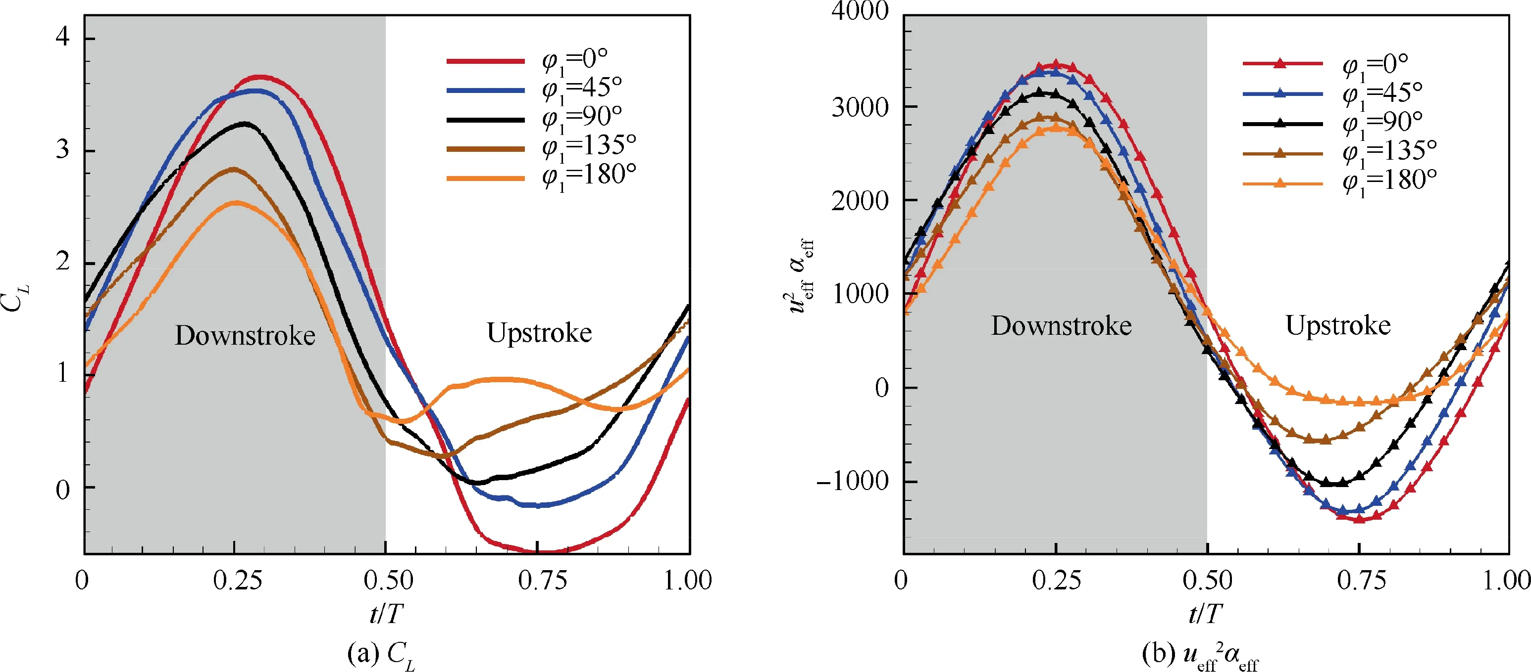
Fig. 16 Instantaneous total lift coefficients CL and ue2ff αeff for different φ1 during a flapping cycle.
The instantaneous total lift coefficients for different φduring a flapping cycle are shown in Fig. 16(a). As φincreases,the peak value of the positive lift of E377m airfoil descends while the valley value of the negative lift increases.As a result,the mean lift coefficient first increases and then decreases with φcontinuously increasing, reaching a maximum value at about φ=45°in this study.Besides,the peak value of instantaneous lift coefficients and their relative magnitude under different φare consistent with uα, as depicted in Fig. 16,indicating that both αand usignificantly influence the instantaneous lift of surging airfoil.
3.2. Mechanisms of surging motion regulating lift performance
In Section 3.1, the surging motion has been proved to be a powerful ability to improve the aerodynamic performance of flapping airfoil by adjusting φ. To further explore how flapping airfoil improves lift performance by adding surging motion, the flapping motion of E377m airfoil with the highest lift coefficient and lift efficiency are obtained through optimization in this part. Then, the surging motion is removed in the highest lift case and highest lift efficiency case respectively, to figure out the mechanism by which surging motion adjusts the aerodynamic force and efficiency.
3.2.1. Mechanism of surging motion to increase lift
In this part, trajectory optimization is carried out in the pitching-plunging-surging combined E377m airfoil to maximize its C. The C, ƞ, and ƞof E377m airfoil are constrained to be greater or equal to those of E377m airfoil without surging motion in Fig.9.The optimization mathematical model is of the form:

where C=0.1175, ƞ=2.75, ƞ=0.239.
The motion trajectory of E377m airfoil is determined by the Y, α, α, φ, surging amplitude X, φ, and f, as shown in Eq. (1). In this study, Yand f are set to constant values to ensure that the Strouhal number (St) does not change in various motion trajectories, where Y=1.0c and f=12 Hz.Hence, only five kinematic parameters (α, α, φ, X, φ)are adopted as design variables during optimization. The upper and lower limits of the design space for the design variables are shown in Table 3.
An in-house optimization platform named‘‘SurroOpt”is used in this study.20 initial samples are chosen by the Latin Hypercube Sampling (LHS)method to build an initial kriging model for the objective function. Then the Expected Improvement (EI) and Minimizing Surrogate Prediction (MSP) infillsampling criterion are used to select new samples to updatethe kriging model until the global optimum is found.The convergence history is sketched in Fig.17,the motion trajectory of E377m with maximum Cis obtained after approximately 77 evaluations.The optimization results are shown in Table 4.The mean lift coefficient of E377m airfoil is increased by 65.9% after motion trajectory optimization.

Table 3 Upper and lower bounds of design variables.
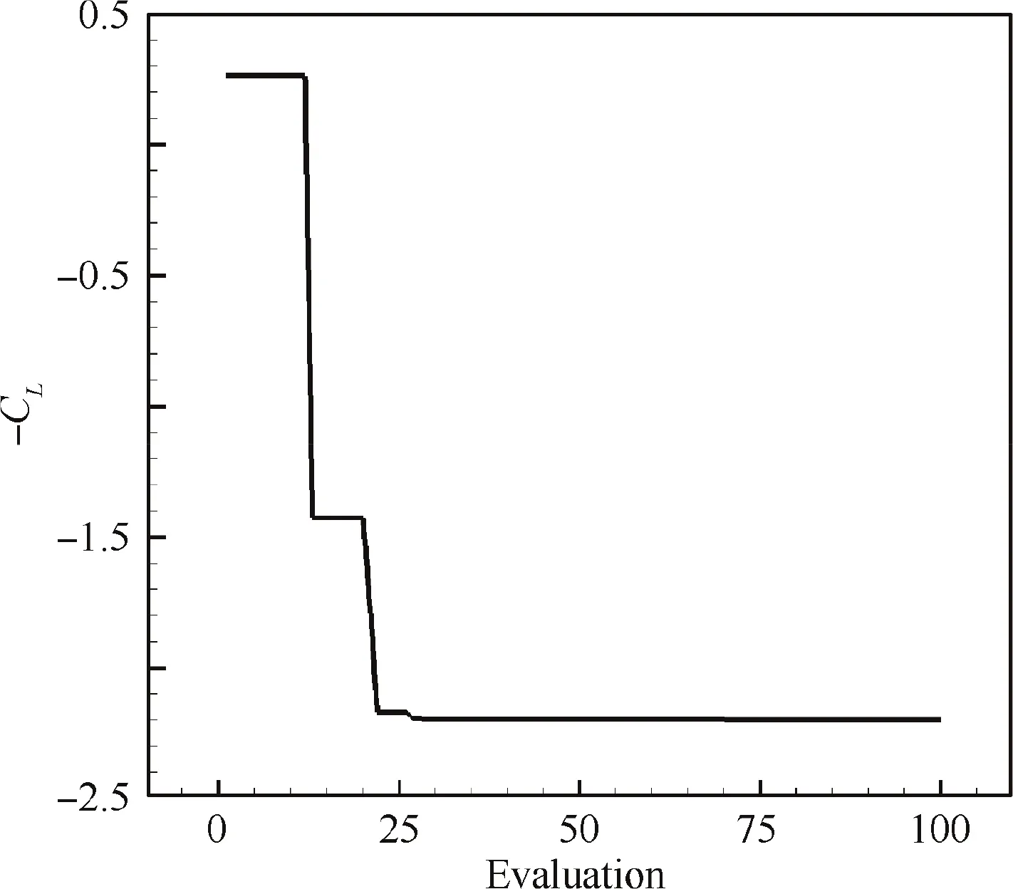
Fig. 17 Convergence history of optimizing flapping motion of E377m airfoil using kriging-based methods.
As shown in Fig. 18(a), the optimal case shows an oblique straight trajectory (φ=0°), of which the airfoil sweeps forward during downstroke and sweeps backward during upstroke. This is qualitatively similar to the movement of the wingtip when a bird takes off at low speed(Fig.18(b)).To further explore how flapping airfoil achieves lift performance by adding surging motion, numerical simulations are carried on the optimal trajectory by keeping surging motion and deleting surging motion. Results are shown in Table 5. The Cof E377m airfoil is reduced by 37.9% if surging motion is removed from kinematic, which indicates that the surging motion with φ=0°is very important for generating high lift.
The instantaneous lift coefficients for optimal trajectory which keeps surging motion and deletes surging motion during a flapping cycle are depicted in Fig. 19 (a). During the whole downstroke, the airfoil with surging motion generally has a much higher transient Cthan the airfoil without surging motion.It can be observed from Fig.19(b)that αof flapping trajectory with surging motion is less than that of flapping trajectory without surging motion during the whole downstroke.Correspondingly,the formation of LEV on the suction surface of E377m airfoil with surging motion is much later (see Fig. 20). uof flapping trajectory with surging motion is greater than that of flapping trajectory without surging motion during the whole downstroke. During the early downstroke, a much larger value of uhelps to enhance the positive pressure on the lower surface of E377m airfoil,and it also helps to produce stronger suction on the upper surface of E377m airfoil,as shown in Fig.21(a)and(b).Hence,E377m airfoil with surging motion has better lift performance when t is less than 0.3 T.During the later stage of downstroke, the LEV is formed on the airfoil with surging motion,meanwhile remaining attached on the upper surface of airfoil, as shown in Fig. 21(c), which helps to generate large vortex lift. As for the airfoil without surging motion,the LEV has been already to fall off the airfoil surface, which leads to loss of total lift. Hence, E377m airfoil with surging motion has better lift performance when t is greater than 0.3 T. In conclusion, the mechanism of surging motion in optimal trajectory to generate high lift is to obtain high attached lift during the early stage of downstroke by enlarging the value of uto increase the pressure difference between the lower and upper surfaces of airfoil. In addition,the optimal trajectory with surging motion is able to generate high vortex lift during the later stage of downstroke by slowlyincreasing αto avoid the premature formation and shedding of LEV.

Table 4 Comparison of kinematic parameters and aerodynamic performance between Baseline case and Opt case.
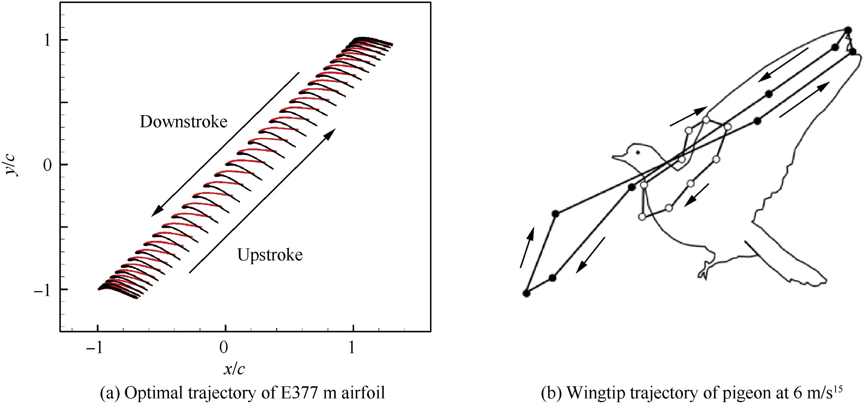
Fig. 18 Comparison of trajectories between E377m airfoil and pigeon wingtip.

Table 5 Comparison of kinematic parameters and aerodynamic performance between optimal trajectory keeping surging motion and optimal trajectory deleting surging motion.
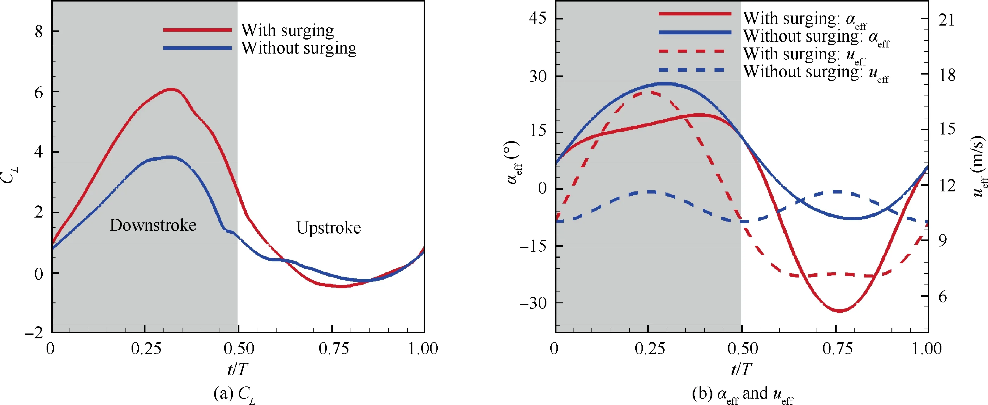
Fig. 19 Instantaneous lift coefficients,effective angle of attack and velocity for optimal trajectory keeping surging and deleting surging motion.
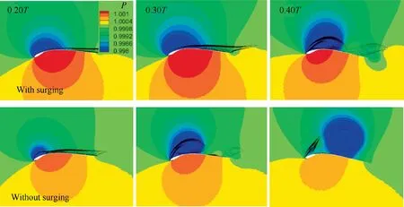
Fig. 20 Comparison of non-dimensional pressure distribution (normalized by far-field pressure) and LEV between optimal trajectory which keeps surging and deletes surging motion.

Fig. 21 Comparison of pressure coefficient between optimal trajectory which keeps surging and deletes surging motion.
3.2.2. Mechanism of surging motion to improve lift efficiency
In this part, trajectory optimization is carried out in the pitching-plunging-surging combined E377m airfoil to maximize its lift efficiency. The optimization mathematical model is of the form:
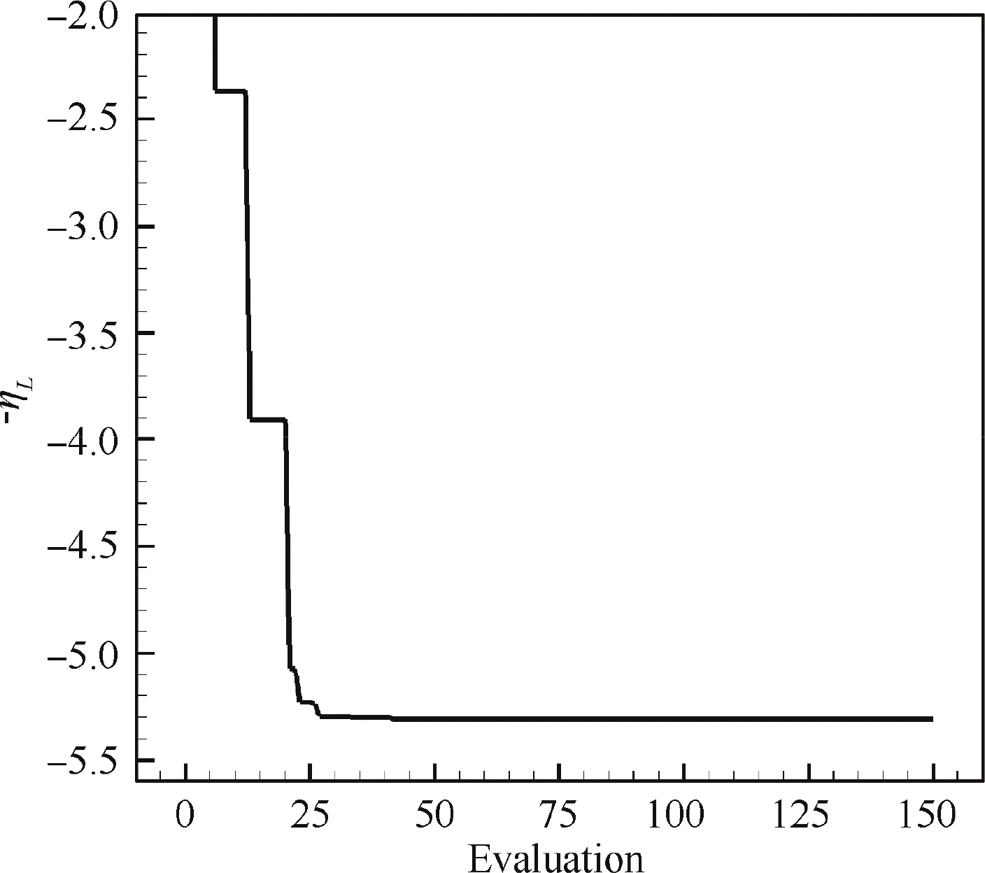
Fig. 22 Convergence history of optimizing flapping motion of E377m airfoil using kriging-based methods.

where C=1.35, C=0.1175, ƞ-=0.239. The design variables and design space are the same as those in Section 3.2.1.
The motion trajectory of E377m with maximum lift efficiency is obtained after approximately 42 evaluations, as shown in Fig. 22. The results of optimization are listed in Table 6. The lift efficiency of E377m airfoil is increased by 106.5%after motion trajectory optimization.The optimal case shows an elliptic trajectory (φ=83°), which is qualitatively similar to the movement of the wingtip during the cruising flight of birds, as shown in Fig. 23.
To further explore how flapping airfoil achieves lift efficiency by adding surging motion, numerical simulations are carried on the optimal trajectory by keeping surging motion and deleting surging motion. Results are shown in Table 7.The surging motion is very important for generating high lift efficiency for the lift efficiency of the airfoil is reduced by 30.0% by removing surging motion.

Table 6 Comparison of kinematic parameters and aerodynamic performance between Baseline case and Opt case.
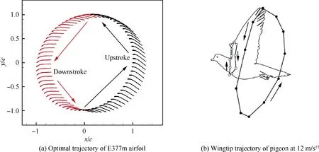
Fig. 23 Comparison of trajectories between E377m airfoil and pigeon wingtip.

Table 7 Comparison of kinematic parameters and aerodynamic performance between optimal trajectories keeping surging motion and deleting surging motion.
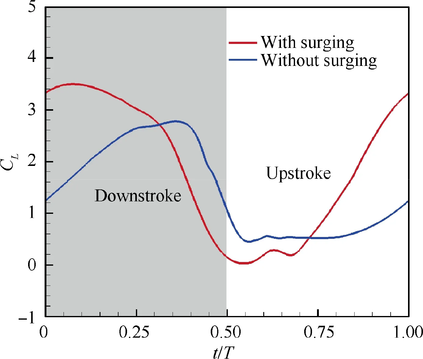
Fig. 24 Instantaneous lift coefficients for optimal trajectory keeping surging and deleting surging motion.
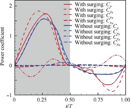
Fig. 25 Instantaneous power coefficients for optimal trajectory keeping surging and deleting surging motion.
It can be seen from Table that lift efficiency is increased mainly due to an increment of time-averaged lift while keeping the power consumption to change little.The instantaneous lift coefficients for optimal trajectory which keeps surging motion and deletes surging motion during a flapping cycle are depicted in Fig. 24. The instantaneous lift coefficients during the early stage of downstroke and the later stage of upstroke are greatly improved, which contributes to total lift enhancement for airfoil with surging motion.In addition,the increase in lift during downstroke will lead to an increase in power consumption,while the increase in a lift during upstroke will reduce power consumption for E377m airfoil with surging motion,compared with E377m airfoil without surging motion (see Fig. 25).Therefore, the E377m airfoil with surging motion improves the time-averaged lift without paying additional energy costs,thereby significantly improving the lift efficiency.
4. Conclusions
In this study,the effects of surging motion on lift performance of flapping airfoil are investigated by numerical simulation.The conclusions obtained are as follows:
(1) Surging motion has a powerful ability to improve the aerodynamic performance of flapping airfoil by adjusting φ. Both lift performance and thrust performance of E377m airfoil are significantly promoted when 15°<φ<90°,compared with the airfoil without surging motion.
(2) The flow pattern and lift performance of E377m airfoil are significantly affected by φ.With φincreasing,both the LEV and the secondary vortex appear earlier on upper surface of the airfoil due to the increase of α.Meanwhile, the contribution of vortex lift to total lift is enhanced at relatively large φ.
(3) An oblique straight trajectory is obtained with φ=0°,which is qualitatively similar to the movement of the wingtip when a bird takes off at low speed,can produce a large lift.The mechanism is mainly due to a much larger value of u,which is achieved during the early stage of downstroke, thus helps to generate attached lift by enhancing pressure difference between the upper and lower surfaces of the surging airfoil. Moreover, by slowly increasing αto avoid the premature formation and shedding of LEV, a large vortex lift is obtained for airfoil with surging motion.
(4) An elliptic trajectory is obtained with φ=83°,which is qualitatively similar to the movement of the wingtip during the cruising flight of birds, can provide a high lift efficiency. The mechanism to improve lift efficiency for airfoil with surging motion is to increase Cduring the early period of downstroke and the later period of upstroke, which can enhance Cwithout paying additional energy costs.
The authors declare that they have no known competing financial interests or personal relationships that could have appeared to influence the work reported in this paper.
Acknowledgments
This work was supported by the National Natural Science Foundation of China(No.11872314),the Key R&D Program in Shaanxi Province of China (No. 2020GY-154).
 Chinese Journal of Aeronautics2022年9期
- Chinese Journal of Aeronautics的其它文章
- Bolt insertion damage and mechanical behaviors investigation of CFRP/CFRP interference fit bolted joints
- Capture and detumbling control for active debris removal by a dual-arm space robot
- Target localization based on cross-view matching between UAV and satellite
- Quick identification of guidance law for an incoming missile using multiple-model mechanism
- Robust image-based coordinated control for spacecraft formation flying
- A novel imprecise stochastic process model for time-variant or dynamic uncertainty quantification
