Robust image-based coordinated control for spacecraft formation flying
Dayong HU, Xiangtian ZHAO, Shijie ZHANG
Research Center of Satellite Technology, Harbin Institute of Technology, Harbin 150080, China
KEYWORDS Algebraic graph theory;Coordinated control;Image-based visual servoing;Robust control;Spacecraft formation flying
Abstract This paper addresses a coordinated control problem for Spacecraft Formation Flying(SFF). The distributed followers are required to track and synchronize with the leader spacecraft.By using the feature points in the two-dimensional image space,an integrated 6-degree-of-freedom dynamic model is formulated for spacecraft relative motion. Without sophisticated threedimensional reconstruction, image features are directly utilized for the controller design. The proposed image-based controller can drive the follower spacecraft in the desired configuration with respect to the leader when the real-time captured images match their reference counterparts. To improve the precision of the formation configuration, the proposed controller employs a coordinated term to reduce the relative distance errors between followers.The uncertainties in the system dynamics are handled by integrating the adaptive technique into the controller,which increases the robustness of the SFF system. The closed-loop system stability is analyzed using the Lyapunov method and algebraic graph theory.A numerical simulation for a given SFF scenario is performed to evaluate the performance of the controller.
1. Introduction
The concept of Spacecraft Formation Flying (SFF) was proposed in 1977, when Sholomitsky et al. studied infrared synthetic aperture imaging using multiple spacecraft.With the development of small spacecraft and inter-satellite relative measurement and control technology, numerous formation flying missions have been performed, such as the Cartwheel missionand TanDEM-X missionfor Earth observation,the Stellar Imager missionand SULFRO missionfor deep space exploration, and the PRISMA missionand Proba-3 missionfor in-flight formation flying demonstration. Closedistance coordinated work is a basic characteristic of SFF.The formation mission requires the spacecraft to maintain a particular geometry and relative-motion relationship. However, owing to the complex orbit–attitude coupled dynamic characteristics of the spacecraft, the geometry and relative motion are time-varying,and perturbation leads to uncertainty of this variation. Therefore, high-precision coordinated control is the key problem in SFF missions.
The architecture of the spacecraft formation coordination should consider the information interaction and control association between spacecraft members on both logical and physical levels.The architecture of coordinated spacecraft formation is classified into two types: centralized and decentralized configurations.In the centralized formation configuration, one spacecraft is regarded as a global control agent,which forms the control strategies for the entire formation and then distributes the control signals to the other spacecraft in the formation.Therefore,extensive inter-satellite information transmission and processing are required.Compared with centralized configurations, decentralized ones have little communication traffic and thus possess high fault-tolerance and robustness.The distributed structure is one of the most common decentralized configurations. Each spacecraft in the distributed configuration can make independent decisions and interact with neighboring spacecraft.Using the individual observations and information about interactions with other spacecraft,each spacecraft can determine its own control strategy, which results in the desired formation flying pattern.
According to different control objectives the coordinated control for SFF can be divided into coordinated attitude control,coordinated position control,and coordinated orbit–attitude coupled control.In the literature, coordinated control is usually combined with other control techniques to achieve more versatile control tasks and performance, such as finite-time control,fixed-time control,adaptive control,artificial potential function-based control,containment control,and optimal control.In actual spacecraft formation missions,the attitude and orbital motions of the spacecraft are strongly coupled.With separate consideration of the attitude and orbital coordinated control, the coupling effect is ignored, which may result in a low control accuracy. Therefore, coordinated control with coupled orbit–attitude dynamics in SFF is more attractive and challenging and has been investigated in recent studies.In Ref.,a robust adaptive finite-time control strategy based on coupled 6-Degree-of-Freedom (6-DoF) dynamics was proposed.Artificial potential functions are integrated into the controller to handle the motion constraint. A distributed output feedback controller was presented in Ref.for 6-DoF spacecraft formation subject to input saturation. A coupled model based on dual quaternions was utilized in Ref.for 6-DoF spacecraft formation control.
With regard to coordinated formation control, the leader–follower method has the advantage of simplicity in design and can transform the formation control problem into a single spacecraft-tracking problem.Generally, the orbital maneuver of the follower spacecraft requires either the relative measurement with respect to the leader or inter-satellite communication. The vision-based relative measurement depends on sophisticated three-dimensional (3D) reconstruction, which usually requires a large amount of onboard computational resources—particularly for small satellites with limited computing capabilities.Additionally, frequent information interaction with followers can impose a significant communication burden on the leader spacecraft. An effective alternative called image-based visual servoing (IBVS) is used in vision-based control for robot manipulators.In this method,the task function is directly defined in the two-dimensional(2D) image space using the projected feature points.The robot/vehicle can be driven to the desired pose with respect to the target by matching the real-time captured images with their reference counterparts, which avoids reconstructing the relative pose information in real time. The IBVS method is commonly applied to the second-order dynamic system in Unmanned Aerial Vehicle (UAV) control.The control of UAVs is similar to the control of spacecraft systems in many aspects. The system dynamics of both UAVs and spacecraft formation are highly coupled and nonlinear. The coupling of UAV dynamics—particularly quadrotor dynamics—mainly arises from the underactuated nature of UAVs;i.e.,the vehicle will inevitably tilt when maneuvering horizontally. For spacecraft formation control, we must establish the relative system dynamics between two satellites. The coupling of relative motion equations mainly arises from the rotation of feature points around the target’s center of mass (COM). In Ref.,an image-based proportional–derivative (PD) controller was developed for spacecraft rendezvous and docking and tested using a free-floating platform. In Ref., two control schemes based on the IBVS method were presented, which can be used to not only rendezvous to but also synchronize with tumbling space debris. A similar problem was addressed in Ref.,where an integrated orbit–attitude IBVS controller using a zooming camera was proposed. In contrast to the singlespacecraft tracking problem considered in Refs., a cyclic leaderless tracking problem involving four satellites in a formation was investigated in Ref., where the IBVS algorithm was combined with the optimal control theory to reduce the fuel consumption. However, the system dynamic model presented in Ref.does not take into account the kinematic coupling effect arising from the target’s motion. Additionally, the inter-satellite communication and the resulting formation topologies were not considered in Ref..
This paper provides a solution to the problem of coordinated control of SFF based on the IBVS method. The proposed framework essentially consists of a combination of navigation and control operations in which current image features are matched with their desired counterparts. The main contributions of this study can be summarized as follows:
(1)Compared with the pose-based relative system dynamics presented in Refs.,an integrated 6-DoF relative dynamic model for SFF is constructed using the 2D image features,where the uncertainties related to the leader’s rotation and external disturbances are considered simultaneously. An image-based controller is presented for each follower spacecraft to achieve both relative position tracking and attitude synchronization with the leader.
(2) Compared with the previous image-based spacecraft control studies of Refs., the image-based control scheme is combined with the algebraic graph theory in the SFF mission. By involving a coordinated term in the IBVS controller,the coordinated errors in the formation configuration can be reduced significantly.
(3) To handle the uncertainties in the image-based relative dynamic system,which were not addressed in Ref.,the adaptive technique is integrated into the controller design, which facilitates stability analysis and improves the robustness of the SSF system.
The remainder of this paper is arranged as follows.Section 2 formulates the SFF problem and presents mathematical preliminaries.The visual servoing model for SFF is derived in Section 3. In Section 4, an image-based coordinated controller is developed, and the stability of the closed-loop system is confirmed.A numerical simulation for a given SFF scenario is presented in Section 5. Section 6 concludes the paper.
2. Problem formulation and mathematical preliminaries
2.1. Problem statement
There is a notable trend in the current development of space technology toward the replacement of a single, large satellite with a formation of multiple small satellites—particularly micro- and nano-satellites.To meet or even exceed the performance of the large satellites, networked small satellites in the formation are subject to two main challenges:miniaturization and achieving a high control accuracy.Miniaturization of the spacecraft implies limited computational resources, a limited communication bandwidth, etc. An alternative approach to addressing such a problem is adopting the IBVS strategy during the formation control, which can avoid sophisticated 3D reconstruction and direct communication with the leader spacecraft. Furthermore, image data reflect the movement of the spacecraft with six degrees of freedom; i.e., the orbit–attitude coupling is naturally included in the IBVS model.The integrated control strategy based on this coupled model can significantly improve the control accuracy in formation flying.
The satellites examined in this study are supposed to follow a distributed formation structure, where a combination of the leader–follower and algebraic graph methods is adopted for specific space missions, e.g., synthetic aperture imaging and Earth observation. The spacecraft formation configuration is illustrated in Fig.1.The SFF system consists of a group of followers that form a regular polygon and fly around a leader spacecraft.The followers are initially positioned tens of meters from the leader to form and hold the predetermined configuration.During the formation flying,the followers are required to track the leader spacecraft,which can be continuously maneuvering according to imaging or observation missions.Each follower spacecraft collects image data of the feature points marked on the leader using an onboard camera. It is assumed that a set of predetermined image figures captured by the same camera in the desired configuration with respect to the same markers on the leader have been stored on the onboard computer of the follower. Image data of more than three feature points contain 6-DoF relative-motion information with respect to the leader. Therefore, by matching the current captured image features with their desired counterparts, the follower spacecraft can track the orbital motion of the leader spacecraft at the predefined position, as well as synchronize with its attitude. Additionally, the followers with the distributed configuration can receive/send the collected image data from/to their nearest neighbors. The communication topology between followers is designed to be undirected. By integrating the algebraic graph into the image-based control scheme, a higher relative control accuracy between the followers can be achieved, which facilitates the maintenance of the formation configuration.
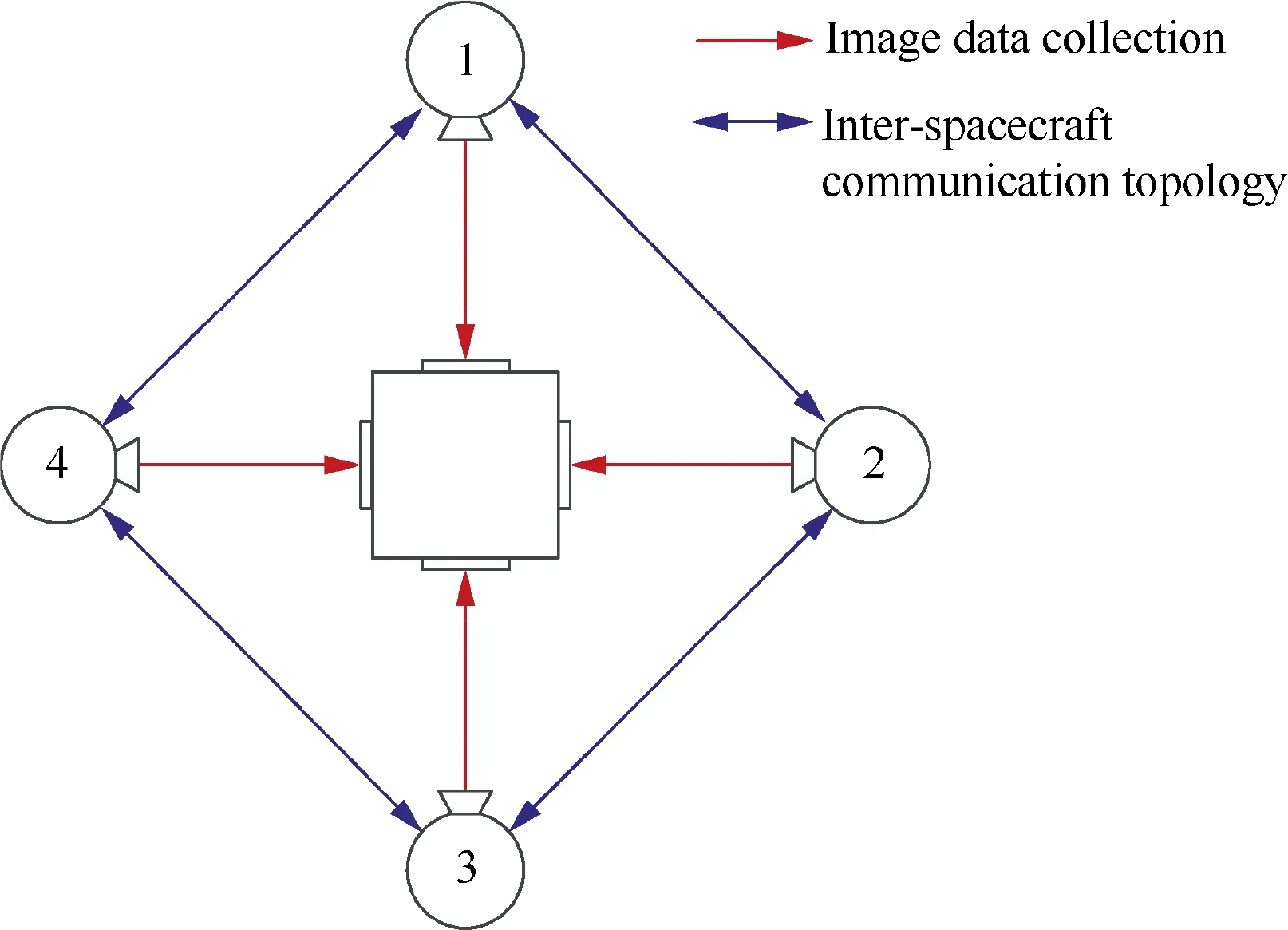
Fig. 1 Spacecraft formation configuration and communication topology.
2.2. Algebraic graph theory
Algebraic graph theory is a mathematical means of building pairwise relationships between objects using graphs. As a natural description of the networked system, graph theory provides a variety of algebraic expressions, which can not only intuitively describe the inter-object interaction but also contribute to investigating the effect of the interaction on the entire system. Therefore, algebraic graph theory is regarded as a powerful mathematical tool for studying coordinated control of SFF.
Considering a group of N follower satellites, the graph of the group can be mathematically defined as G =(V,E,A),where V ={v,v,...,v} is the set of vertices corresponding to the group members, E ⊆V×V is the set of edges describing the inter-spacecraft information interaction, and A =[a]∈Ris the weighted adjacency matrix. In the formation configuration addressed in the present study,(v,v)∈E indicates that the jth spacecraft has access to the information of the ith spacecraft. For any edge (v,v)∈E, if there exists a corresponding edge (v,v)∈E, i≠j, and i,j =1,2,...,N, the specific graph is called ‘‘undirected,” as shown in Fig. 1. The elements of the weighted adjacency matrix are defined as follows:

The communication capability is a formidable technical challenge for small satellites because of their limited size and power production.However,as reported in Refs.,the current state-of-the-art technology can satisfy the expected demand of communication bandwidth for small satellites,although there remains considerable room for improvement.Examples of small SFF with inter-satellite communications can be found in missions, such as PRISMA, Iridium, Proba-3, EDSN, QB-50, etc. Further, this study adopts the IBVS strategy for the follower tracking and avoids direct communication with the leader spacecraft, which can reduce the communication burden of the follower satellites. Therefore, the communication bandwidth is assumed to be sufficient for spacecraft coordinated control in this study.
2.3. Mathematical model for SFF
To describe the mathematical model of the spacecraft in the formation system, we first present several relevant coordinate frames, as shown in Fig. 2.
(1) Earth-centered inertial (ECI) coordinate frame{F}≜{X,Y,Z, which is fixed at the Earth center
(2)Body-fixed frames {F}≜{X,Y,Z.The body frame of the leader is denoted as {F}, and {F} with i ∈{1,2,...,N} represents the follower’s body frame.
(3) Local-vertical, local-horizontal coordinate frame{F}≜{X,Y,Z, whose origin is located at the COM of the leader spacecraft. The Xaxis is directed radially outward from the spacecraft, Zis normal to the orbital plane and is positive in the direction of the angular momentum vector,and Yis defined as the cross-product of the other two axes.
Assuming that the leader spacecraft is moving in a circular orbit, the orbital dynamics of a single follower spacecraft can be described in the {F} frame using the Clohessy–Wiltshire equations:
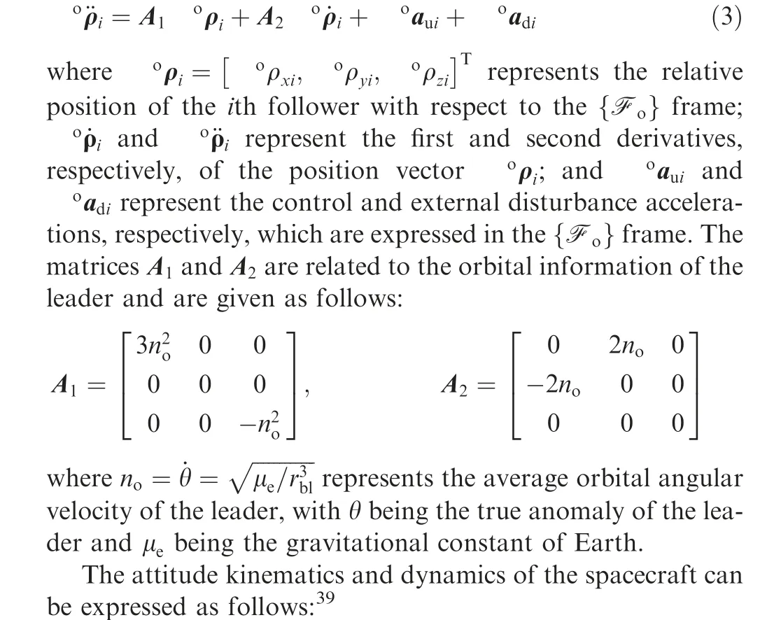

Fig. 2 Definition of the reference coordinate frames.

3. Visual servoing model for SFF
The equations of motion of the spacecraft addressed in Section 2 are established in the 3D Cartesian space. In contrast to the conventional methods presented in Refs., which are based on the estimated 3D pose information in the control loop,the proposed control strategy employs 2D image features as the state errors to track the motion of the leader.Therefore,the kinematics and dynamics of the spacecraft relative motion should be re-established in the 2D image space; i.e., an IBVS model is required for the SFF system.
3.1. Kinematic model of image features
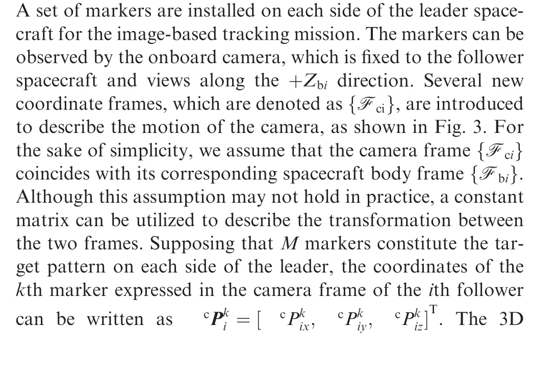
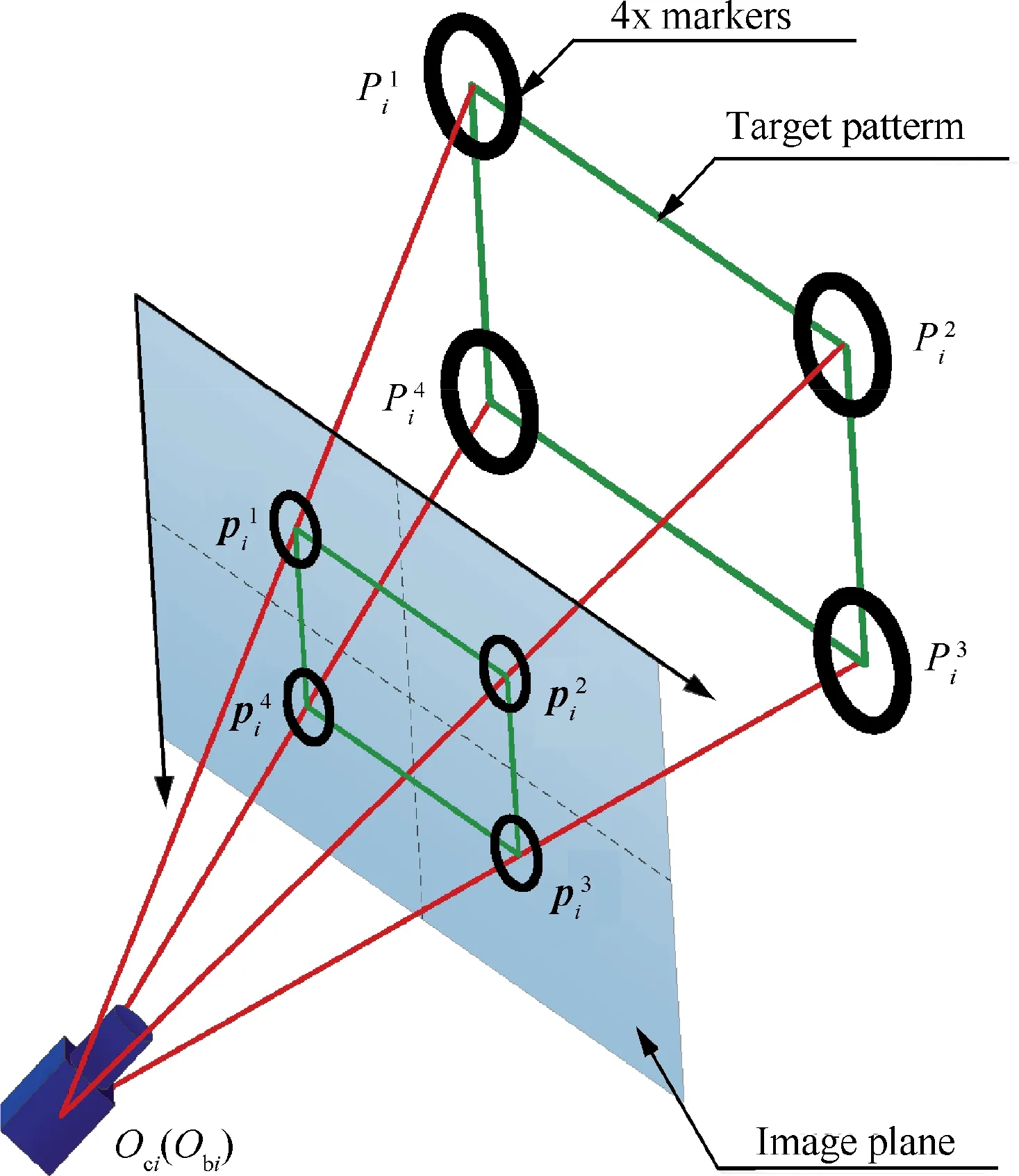
Fig. 3 Pinhole camera model and perspective projection of feature points.


3.2. Dynamic model of image features
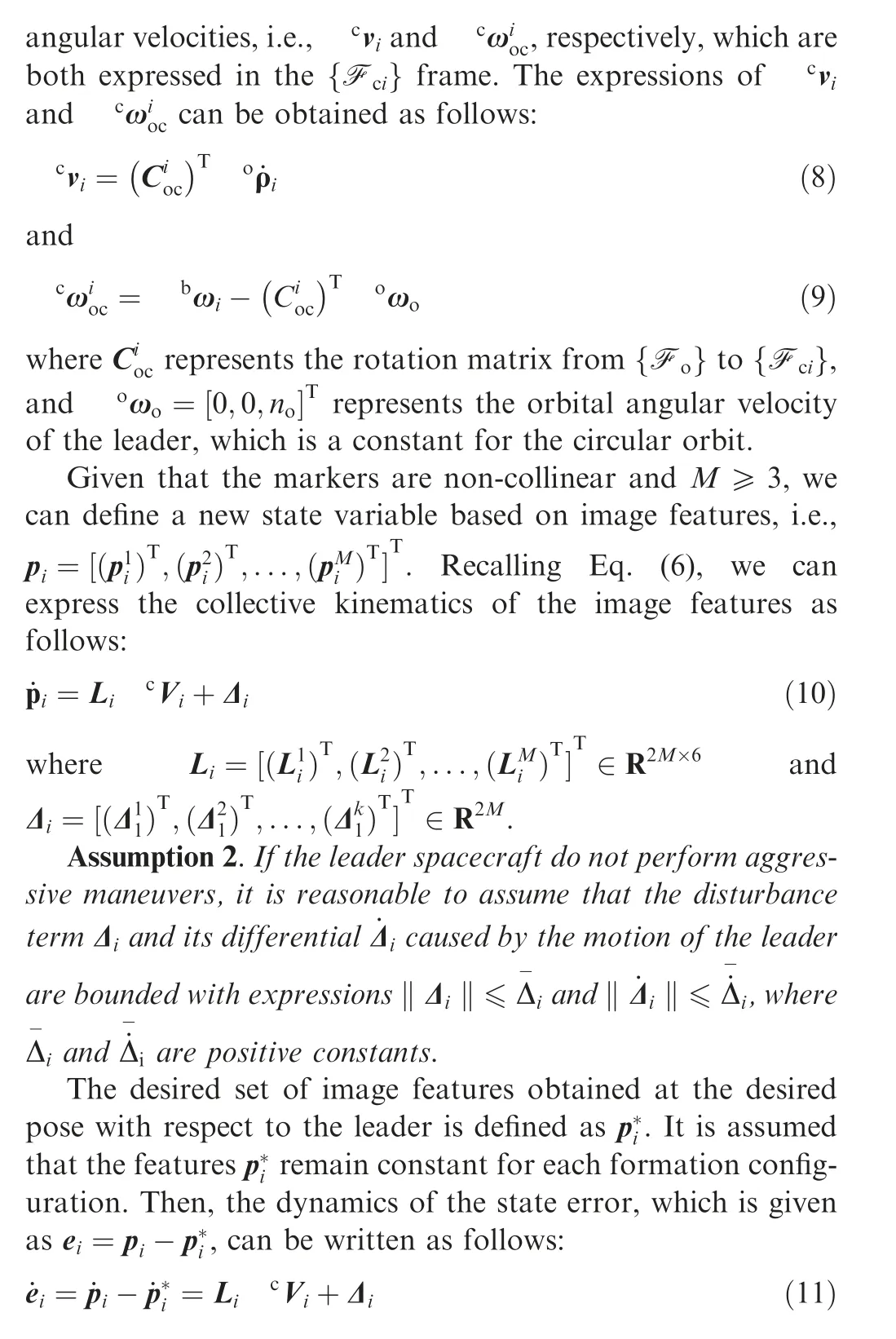
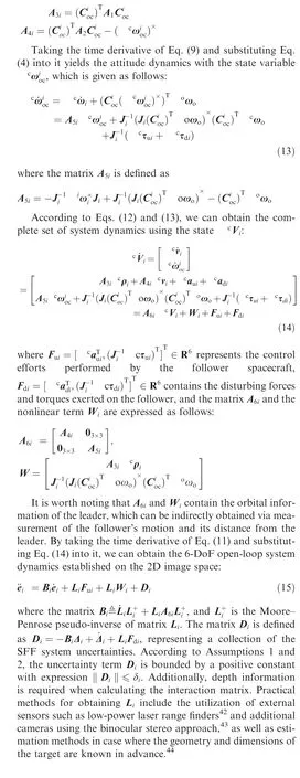
To obtain the command forces and torques to track the leader spacecraft,we must relate the image features with the SFF system dynamics.By taking the temporal derivative of Eq.(8)and substituting Eq.(3)into it,we can obtain the orbital dynamics related to the state variablevas follows:

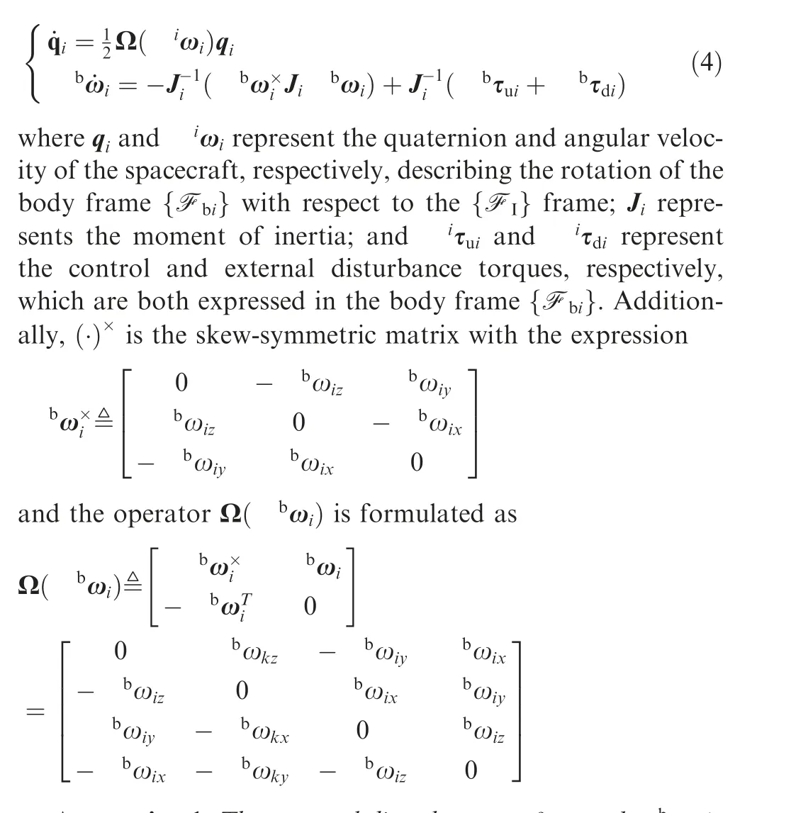
Here,ρrepresents the relative position of the ith follower with respect to the {F} frame and expressed in the{F} frame;aandarepresent the control acceleration and external disturbance acceleration, respectively,expressed in the{F}frame;and the matrices Aand Aare defined as follows:
4. Controller design and stability analysis
A block diagram of the IBVS scheme for a single follower spacecraft is shown in Fig. 4. The control objectives for the SFF mission addressed in this study can be summarized as follows: (A) position tracking and attitude synchronizing of the distributed followers with the leader spacecraft using image states; (B) high-accuracy stabilization of the spacecraft formation configuration; and (c) robustness to the system uncertainties. In this section, a sliding mode control strategy that combines the leader–follower and algebraic graph methods is presented to complete these control objectives.
4.1. Robust image-based coordinated controller

where γand σare positive real numbers.
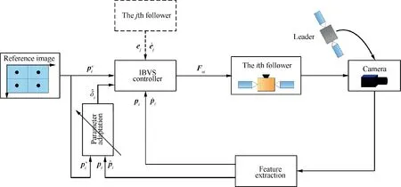
Fig. 4 Block diagram of the IBVS scheme for a single follower in the SFF.
Remark 1. The tracking term in the control law allows the follower spacecraft to track the trajectory of the leader while synchronizing with the leader’s rotation. The nonlinear term is known to the follower spacecraft and can be compensated in real time.The robustifying term is used to restrain the effect of the uncertainties caused by image variation and external disturbances. The coordinated term is responsible for maintenance of the formation configuration. Owing to the perturbations and uncertainties, there are control errors in pose tracking. By compensating for the difference of the sliding mode manifolds between neighboring followers, the relative position and attitude errors between the followers can be reduced significantly.
4.2. Stability analysis
Theorem 1. Consider the image-based system dynamics described by Eq. (15) with Assumptions 1 and 2. If the coordinated controller is designed using Eqs. (18) and (19) and the adaptive law is assigned as in Eq. (20), the sliding mode manifolds sand variables ^δare uniformly ultimately bounded(UUB), and the state errors eand ˙ewill finally converge to a small neighborhood of zero.
Proof. A candidate Lyapunov function containing all system states sand δis designated as follows:


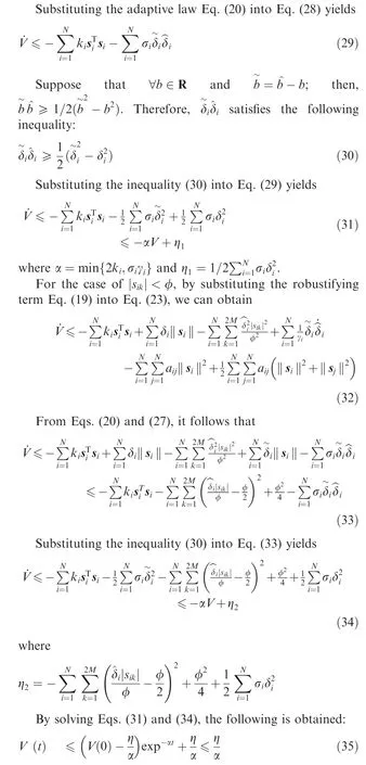
This implies that the variables sand δ~i are UUB. Then,from the sliding mode manifold in Eq. (16), we can conclude that eand ˙ewill converge to a small domain of zero, which guarantees the stability of the entire closed-loop system.
Remark 2.It is worth noting that the ultimate bound of the state errors eand ˙ecan be regulated in terms of the gains selected in the sliding mode manifold and the control law.Increasing the values of matrices Λ, K, and A can reduce the ultimate state errors and accelerate the transient response.However, larger gains result in more control efforts and fuel consumption.
Remark 3. A limitation of the proposed controller is that the input saturation problem is not considered in the closedloop system stability analysis. Limits exist in all types of actuators; thus, we must choose smaller control gains due to limited capabilities of actuators, which may increase the converge time and reduce the control accuracy.If the working ranges of the actuators are too small, system stability cannot be guaranteed,because the fuel that the spacecraft can provide is not sufficient to track the desired trajectory—particularly when the leader is maneuvering.The input saturation problem is an open issue in current studies. Our research on this problem will continue, and we will address it in a future work.
Remark 4. Another potential issue is that the communication resources onboard small satellites are limited. Generally,the undirected communication topology requires a large communication bandwidth and will increase the communication burden to the follower spacecraft. This problem can be addressed by employing the directed communication topology,event-triggered control,quantized information exchange,etc.
5. Simulation results
Numerical simulations were performed to evaluate the proposed robust image-based coordinated controller for an SFF scenario involving a leader spacecraft with four distributed followers. The formation configuration and communication topology of the spacecraft group are shown in Fig.1.The orbital elements that characterize the leader spacecraft are presented in Table 1. The masses of the leader and follower spacecraft are m=110 kg and m=100 (i =1,2,3,4) kg,respectively.Their moments of inertia(kg·m)are as follows:

The leader is assumed to rotate with an angular velocity of[0.02,0.02,0.02]rad to perform an imaging and observation mission,and the followers orbit the leader with the initial position and attitude states listed in Table 2. Each follower spacecraft is equipped with a monocular camera to track and synchronize with the leader during the formation flying. The properties of the onboard cameras are presented in Table 3.Four nonlinear visual markers are selected on each side of the leader’s body for visual servoing. The four follower spacecraft involved in the SFF system are expected to reconfigure to a square, with coordinates of [-20,0,0]m, [0,20,0]m,[20,0,0]m, and [0,-20,0]m, all expressed in the {F}frame. The coordinates of the visual markers and their corresponding desired image features are presented in Table 4.
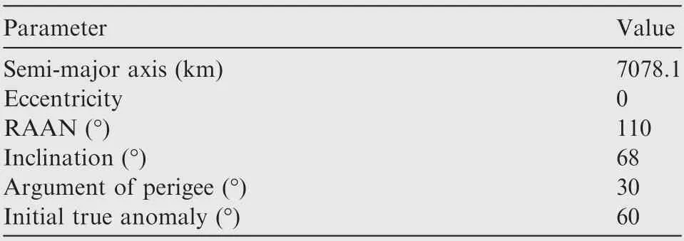
Table 1 Orbital elements of the leader spacecraft.

Table 2 Initial states of the followers.

Table 3 Onboard-camera properties.
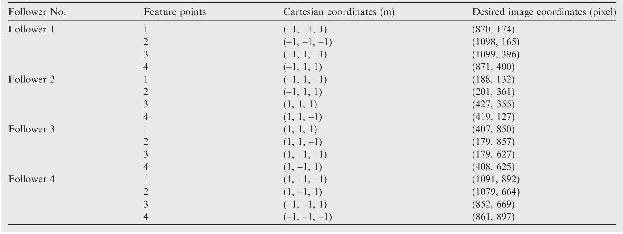
Table 4 Coordinates of the feature points and desired image features.
The perturbation force (per unit mass) and torque exerted on each spacecraft are given as follows:
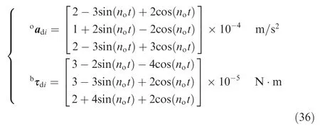
The control forces and torques are provided by thrusters and reaction wheels, respectively. Their maximum outputs are a=0.05 m/sand τ=0.5 N·m. If the theoretical control effort is larger than the maximum value, a saturation function is implemented to generate actual forces and torques,as follows:
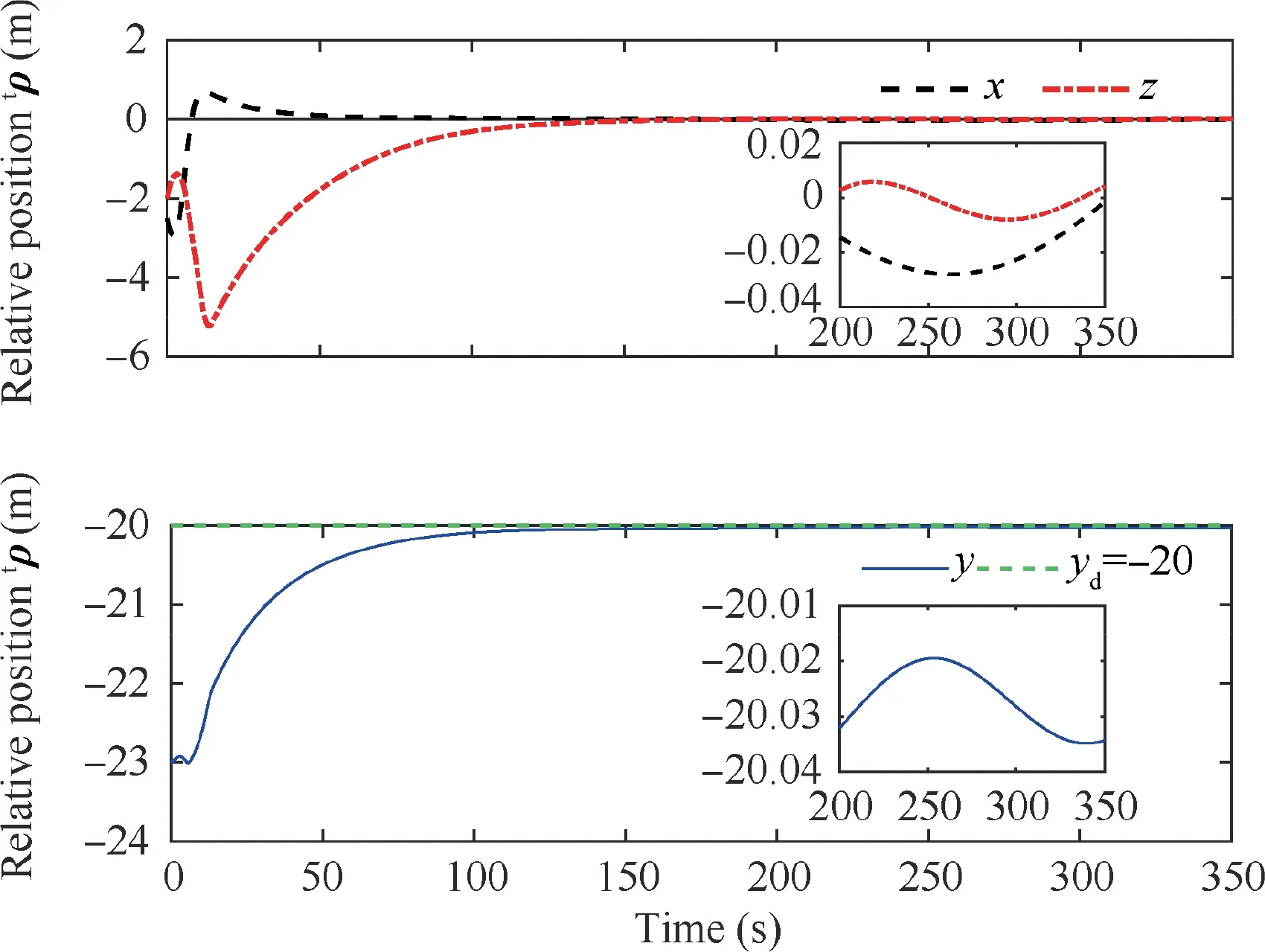
Fig. 5 Time evolution of the relative position.
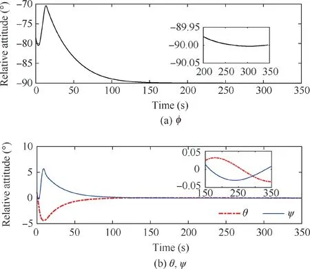
Fig. 6 Time evolution of the relative attitude.
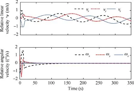
Fig. 7 Time evolution of the relative velocities.
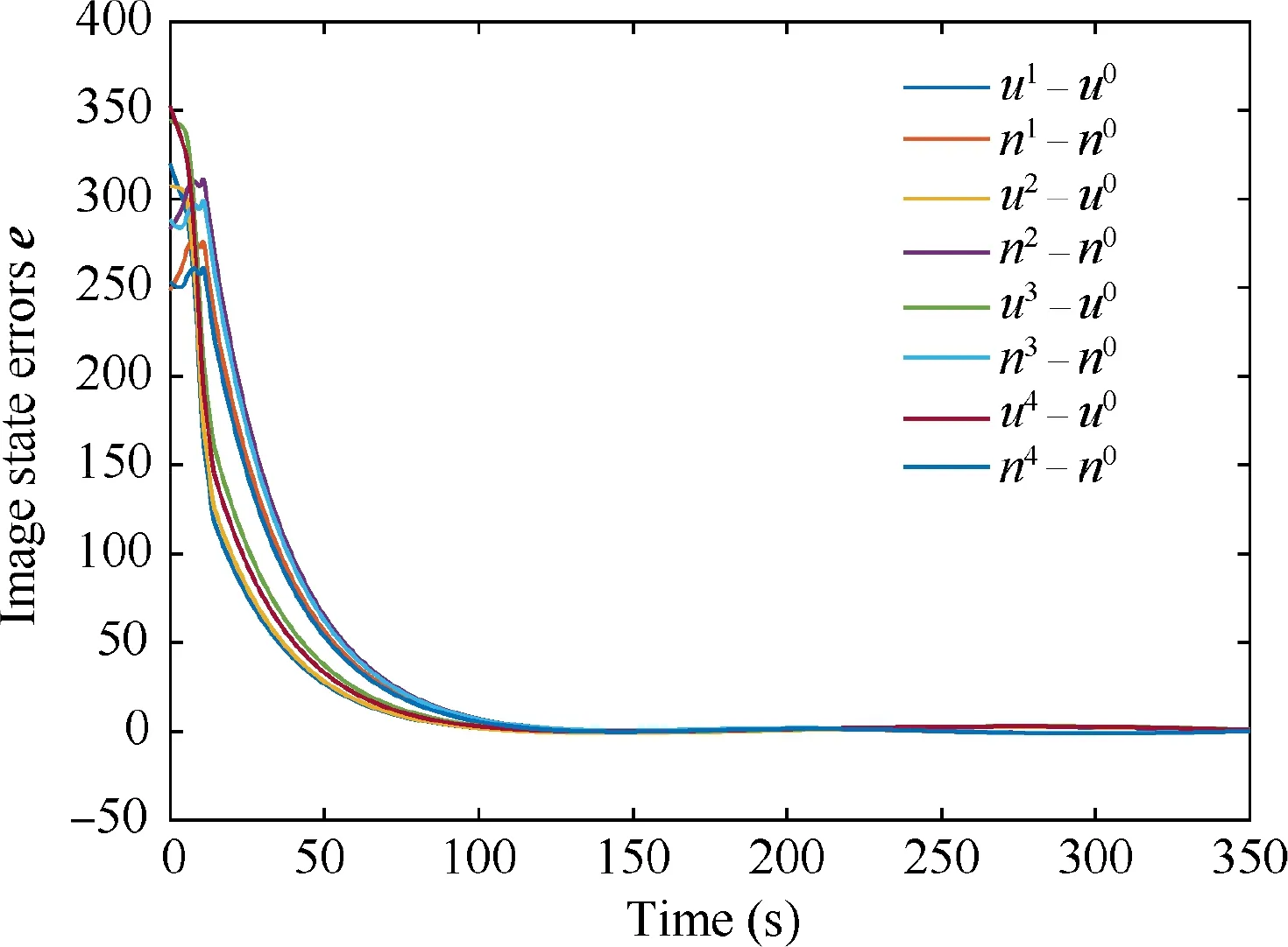
Fig. 8 Time evolution of image state errors.
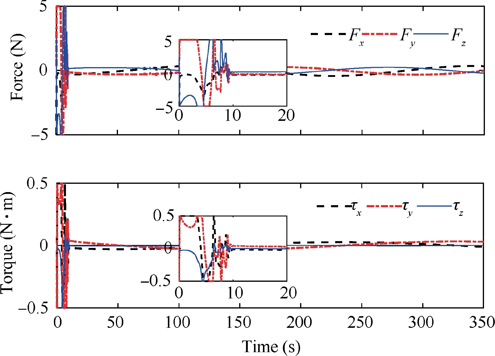
Fig. 9 Time evolution of forces and torques.
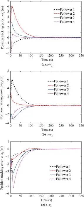
Fig. 10 Position tracking errors along each axis.
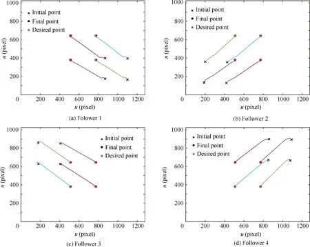
Fig. 11 Feature points trajectories in the image plane.
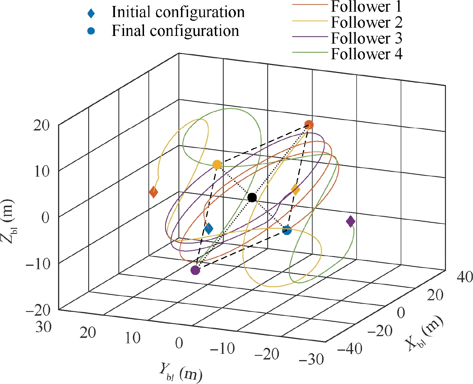
Fig. 12 Trajectories of the spacecraft during the formation flying.

where ς can be aand τ,and ςrepresents the maximum output.
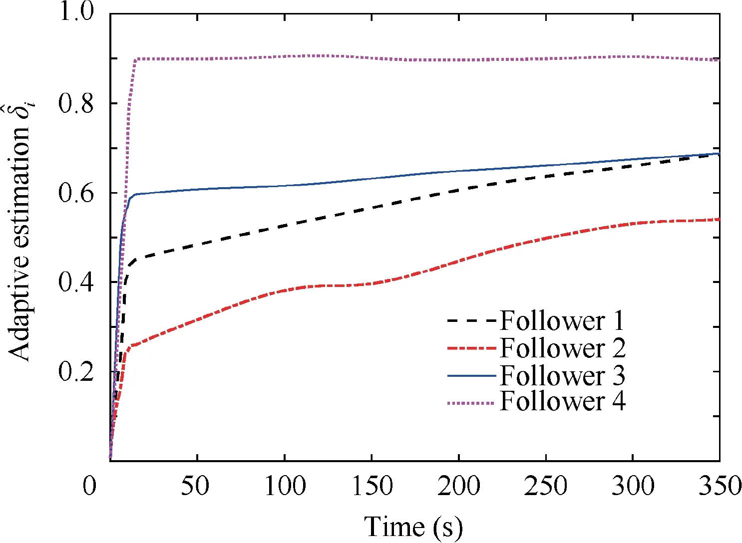
Fig. 13 Time evolution of the estimated parameters.
Using the trial-and-error method,the controller parameters are selected as Λ=0.04I, K=2I, φ =0.3, γ=0.02, and σ=0.2, and the weighted adjacency matrix is set as
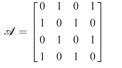
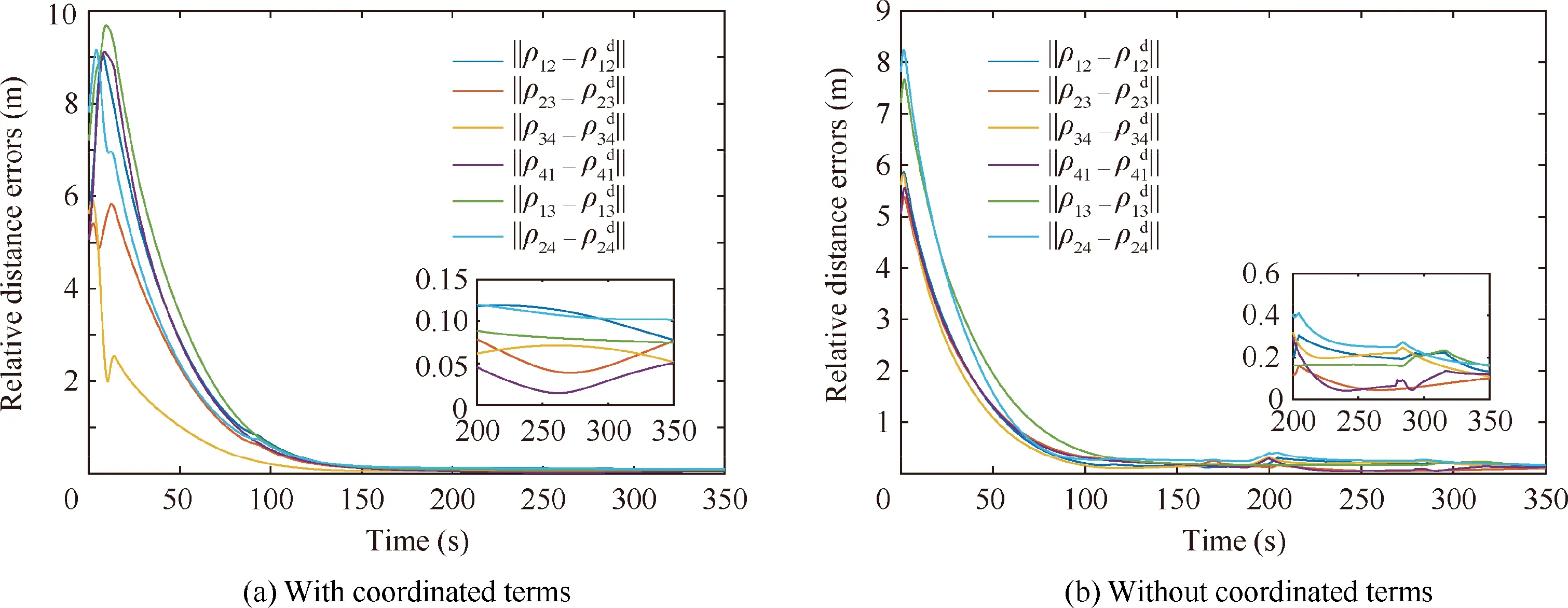
Fig. 14 Time evolution of the relative distance errors.
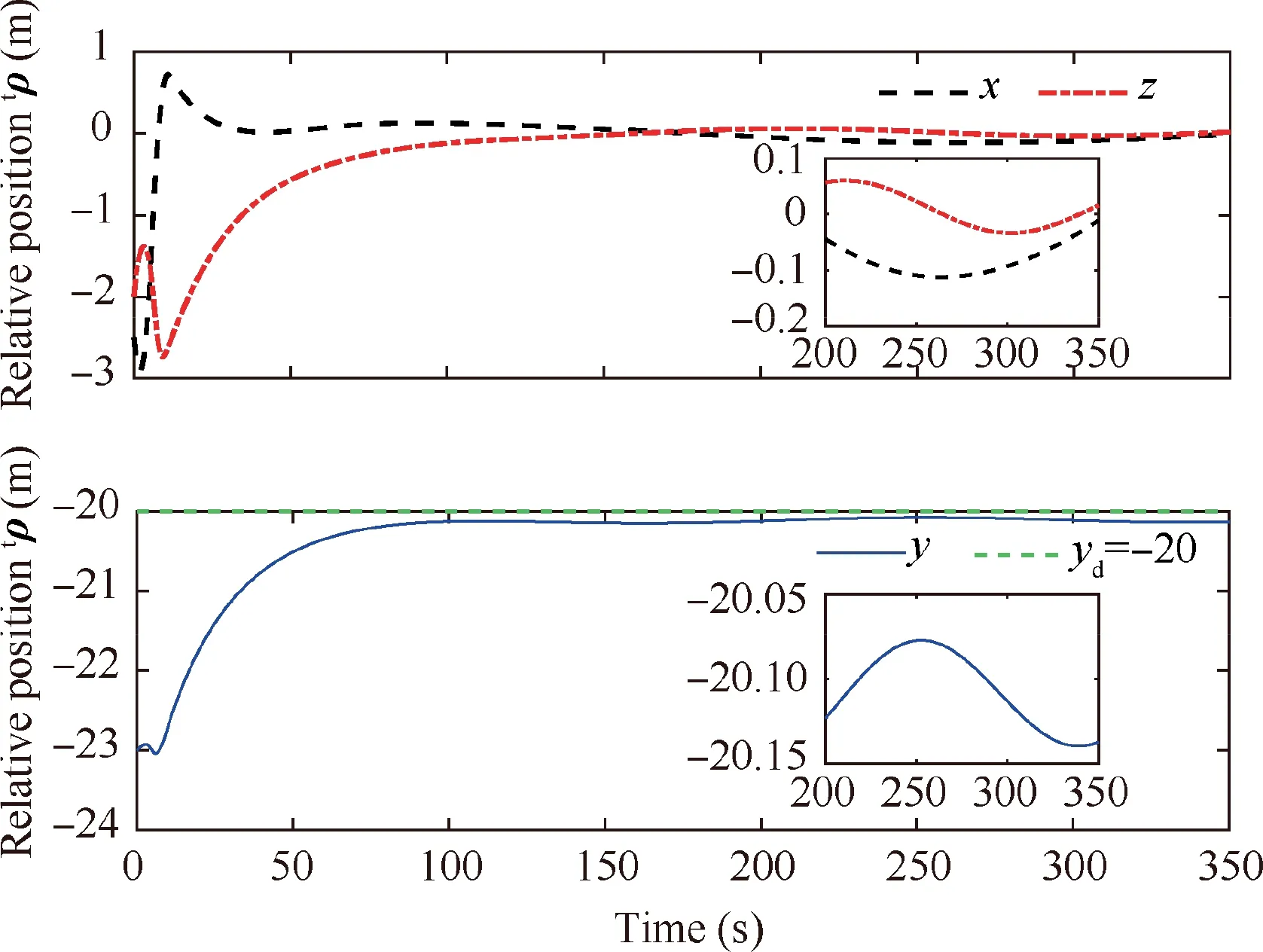
Fig. 15 Time evolution of the relative position for the PD controller.
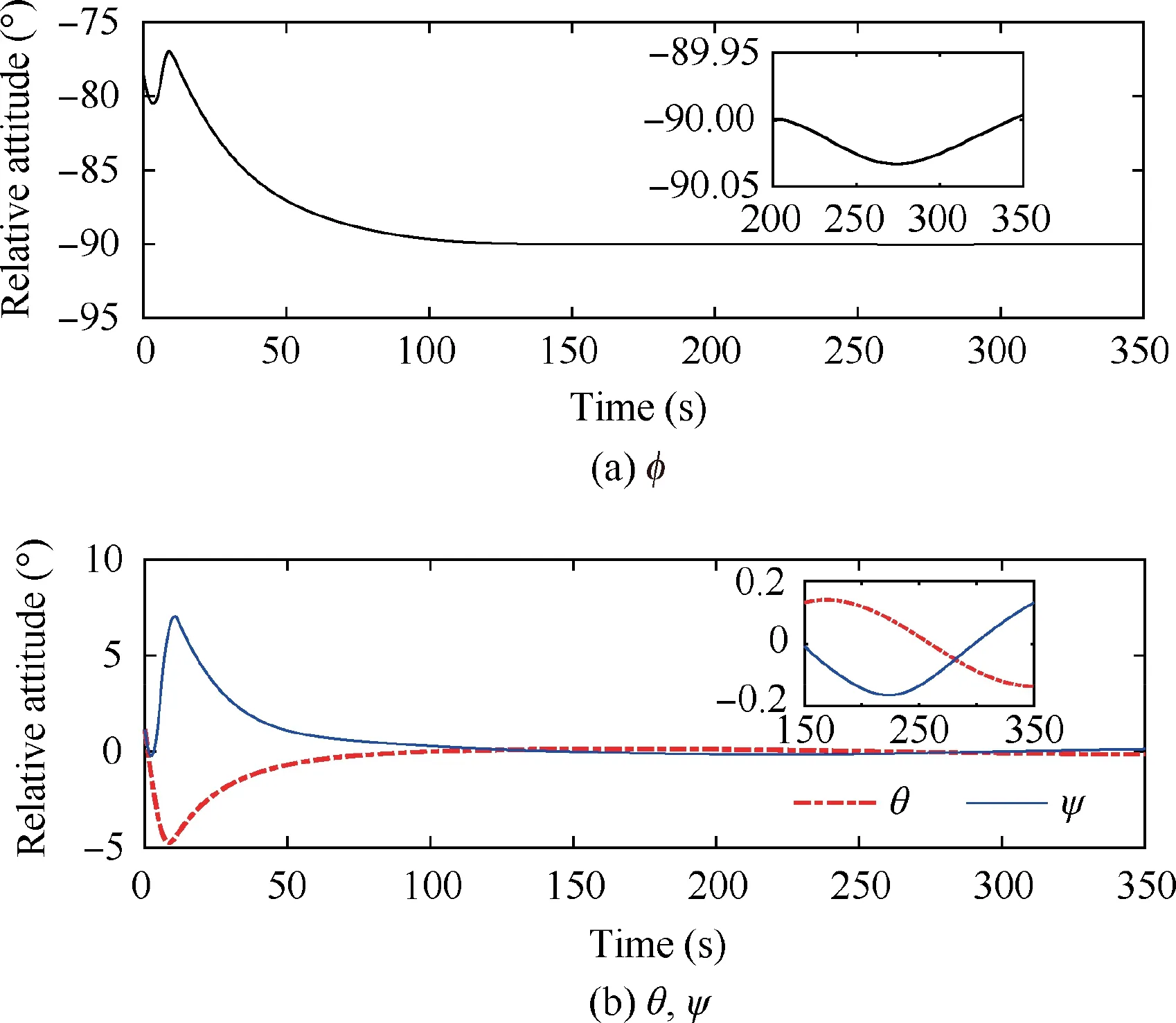
Fig. 16 Time evolution of the relative attitude for the PD controller.
The simulation results for a single follower spacecraft in the formation flying are shown in Figs. 5–10. Fig. 5 presents the relative position of the follower spacecraft with respect to the leader expressed in the {F} frame. As shown, the position tracking error converges to <0.04 m with a settling time of approximately 150 s.Fig.6 shows the relative attitude of the follower spacecraft with respect to the {F} frame with a tracking error of <0.05.The steady-state errors of the relative position and attitude indicate fine tracking performance and attitude synchronization under the proposed image-based controller. The evolution of the relative velocities is shown in Fig. 7. The relative linear velocity of the follower is expressed in the {F} frame. It changes periodically as a result of the leader’s attitude maneuver. Fig. 8 presents the time evolution of eight image state errors corresponding to the four feature points. As shown, the convergence of the defined 2D image states is associated with the convergence of the 3D states of the relative pose. The applied forces and torques on the follower spacecraft are presented in Fig.9,where we observe that the control efforts are bounded by actuator saturation in the first few seconds. The forces and torques decrease rapidly and remain within a small region to compensate for the system uncertainties. Similar results can be obtained for the other three followers.Fig.10 presents the absolute position tracking errors along each axis for the four followers.The performance of the feature points in the image space is illustrated in Fig.11.As shown, the trajectories of the feature points reach their desired position eventually. We can conclude from Figs. 5–11 that the proposed controller can guarantee the SFF with a predetermined formation configuration. Fig. 12 presents the 3D trajectories of the follower spacecraft during the formation flying. Clearly, the followers can form and maintain a square configuration when the leader is rotating.Additionally,the estimated parameters are uniformly bounded,as illustrated in Fig.13.Although these estimations do not converge to their true values,owing to inadequate persistent excitations,the system stability is ensured.
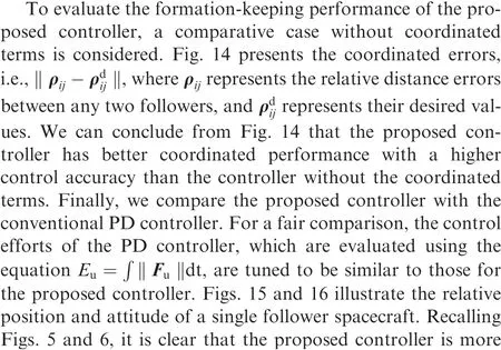

Table 5 Control-performance comparison.

6. Conclusions
This paper proposes a robust image-based coordinated controller for SFF. A linear sliding mode manifold is defined by utilizing 2D image features and their rates.The proposed controller uses three function terms: a tracking term, coordinated term, and robustifying term. The tracking term is responsible for driving the vehicle to the desired configuration with respect to the leader, i.e., following the trajectory of the leader and synchronizing with it.The coordinated term can reduce the relative distance errors between followers and improve the precision of the formation maintenance. The robustifying term is used to restrain the uncertainties in the dynamic model and increase the robustness of the system. According to the Lyapunov method and algebraic graph theory,the closed-loop system is proven to be UUB. The performance of the proposed controller is evaluated via a simulated SFF scenario in terms of three indices,i.e.,the tracking accuracy,coordination accuracy, and robustness.
A future study will address the problem that only some of the followers can obtain the information of the leader spacecraft.
The authors declare that they have no known competing financial interests or personal relationships that could have appeared to influence the work reported in this paper.
