Bolt insertion damage and mechanical behaviors investigation of CFRP/CFRP interference fit bolted joints
Yngjie ZUO, Ting YUE, Ruisong JIANG,*, Zengqing CAO, Liu YANG
a School of Aeronautics and Astronautics, Sichuan University, Chengdu 610065, China
b Xi’an Space Engine Co. Ltd, Xi’an 710100, China
c School of Mechanical Engineering, Northwestern Polytechnical University, Xi’an 710072, China
d Xi’an ASN Technology Group Co. Ltd, Xi’an 710072, China
KEYWORDS Bolted joints;Composite;Damage;Failure;Fatigue life;Interference fit
Abstract Interference fit has advantages in improving fatigue behaviors of composite bolted joints;however, interference fit bolt insertion tends to cause damages in laminates weakening joint mechanical properties.Therefore,an experimental study was conducted to investigate bolt insertion damages of Carbon Fiber Reinforced Polymer (CFRP)/CFRP interference fit bolted joints.Mechanical behaviors of joints were also evaluated experimentally under both quasi-static loads and cyclic loads. Scanning Electron Microscope (SEM) and high-resolution X-ray micro-CT scan were used to examine micro damages in laminates. Damage and failure behaviors of joints were characterized. The results demonstrated that the hole entrance in upper laminate and the laminate boundary near the hole wall were the most critical regions for damages during bolt insertions.However,the influence of those damages on quasi-static failure loads and fatigue failure modes of joints was minimal. Delamination and matrix cracking occurred first in laminates following fiber and matrix fracture in quasi-static tensile tests. Interference fit could improve the fatigue resistance of the laminate hole;however,the bolt seemed to suffer a more critical local fatigue loading condition.This paper can contribute to composite structure designs, especially in understanding damage and failure behaviors of composite bolted joints.
1. Introduction
To meet the increasing competition in aeronautic field, high performance Carbon Fiber Reinforced Polymer (CFRP) is widely applied in new generation aircraft due to its low weight and high mechanical properties,especially in fuselage and wing of large commercial aircraft. Despite advantages in integral design, structural joining in CFRP remains an unavoidable need, mainly arising from production limitations of complex structures and size. Currently, bolted joining technique is the dominant joining method for CFRP structures in aircraft.However,bolted joints represent structural discontinuities, which excite stress intensities and cause drilling damages,and significantly limit the service durability of overall structure.When under cyclic loads,joints tend to cause fatigue damage initiation and even catastrophic failure in structures.Moreover, CFRP bolted joints also exhibit a lower strength efficiency in comparison to metals.It is therefore vital to optimize CFRP bolted joint design to increase the efficiency of overall composite structure.
A large body of literature has investigated mechanical properties of composite bolted joints,and the majority of studies involved joint parameter study. Typically, both tensile and compressive failure load of the joint were observed increasing with the increasing of bolt fastening torque, which increased the force needed to create a significant contact between laminate and bolt.The stress distribution at bolt-hole interface is significantly altered by friction coefficient. Increasing friction coefficient could lead a higher joint strength, for that a major proportion of the load in torqued joints was carried by friction.Moreover, joint geometric parameters also had an important influence on joint mechanical behaviors,such as laminate thickness,width to diameter ratio (w/d),edge to diameter ratio (e/d),fitting tolerance between bolt and hole,etc.Here,fitting tolerance is one of the most important factors in composite joint design.In the early studies,composite joints were generally clearance,and clearance was found to have a significant effect on failure initiation and failure mode of joints, due to that even a small amount of changes in clearance could significantly influence bolt-hole contact area.With further investigating, interference fit was demonstrated to increase the load carrying capacity of joints by improving bolt-hole contact conditions.Moreover, joints with proper interference fit size were also reported to show a higher fatigue resistance.
Despite advantages of interference fit in increasing fatigue life,inadequate interference size could cause damage and even delamination in joint laminates,especially during the interference fit bolt insertion. Only a few literatures reported bolt insertion damage behaviors. The insertion of bolt with a proper interference fit size was reported to contribute to achieving tightly coupled interface.Minimal damage occurred around the hole for 0.4% interference fit size during pin insertion, while micro-scale fiber damage occurred with interference fit size increasing to 1%.Entrance and exit of laminate holes were the most critical for bolt insertion damage.Furthermore, the high bolt-hole friction force caused by large interference fit size was further reported to be the main reason for delamination.These reports mainly focused on damage behaviors caused by bolt insertion, however, the mechanical behavior evolution of the joint after bolt insertion under quasi-static tensile load and cyclic load is rarely involved. Besides, the influence of bolt insertion damage on joint mechanical properties is still unknown. An investigation involved bolt insertion damage and its influence on mechanical behaviors is necessary for optimizing composite joint designs.
In this paper, damage behaviors of CFRP/CFRP interference fit bolted joints during bolt insertion were investigated experimentally. After bolt insertion damage tests, mechanical behaviors of joints were further evaluated under both quasistatic loads and cyclic loads. Influences of interference fit size on both bolt insertion damage and mechanical behaviors of joints were discussed. This paper can contribute to composite structure design, especially in understanding damage and failure behaviors of composite bolted joints.
2. Experimental details
2.1. Interference fit bolt insertion tests
The insertion specimen configuration was designed according to ASTM D5961 Standard,as shown in Fig. 1. The width W and the hole edge distance E of specimens were 30 mm and 15 mm, respectively, and the ratio of hole-hole distance S to the bolt diameter D was 6. The specimen length was designed with 90 mm. Specimen laminates were a carbon/epoxy with lamination sequence [+45/-45/0/+45/90/-45/+45/90/-45]. The nominal ply thickness was 0.188 mm,resulting a nominal laminate thickness t= t= 3.384 mm.A titanium alloy protruding shear head bolt with bolt diameter D = 5 mm was used to fasten specimens. The nut used was designed with a threaded collar with frangible driving element to obtain a designed nominal pre-tightening torque of 0.63 N·m.
As shown in Table 1, four groups of interference fit sizes were considered in bolt insertion tests to understand laminate damage behaviors during interference fit bolt insertion. Here,the relative interference size I was used, which is defined as

where d is diameter of the hole.
An ETM101B material testing machine was used to provide the insertion pressure in tests.The schematic of interference fit bolt insertion progress is depicted in Fig.2.A metal supporting plate with a center hole was used to support the hole exit of the lower laminate,and the center hole diameter was the same with the laminate hole diameter. All bolts of specimens were inserted with a same insertion speed of 1 mm/min. Bolt insertion tests for each group of interference fit size were repeated three times. After bolt insertions, specimens corresponding to different interference fit sizes were cut along A-A by a water jet cutting equipment, and internal damage behaviors on cutting sections were examined by Scanning Electron Microscope(SEM).
2.2. Quasi-static tensile and fatigue tests
2.2.1. Specimen details
The single-lap bolted configuration is widely accepted to represent the configuration of most critical aircraft bolted joint applications.The same single-lap bolted joints(see Fig.3)were used in both quasi-static tensile tests and fatigue tests. Along the bolt insertion direction, the first laminate of the joint was called the upper laminate, and the second laminate was called lower laminate. The two sides of both upper and lower laminates were, respectively,defined as the front side and the back side along the bolt insertion direction. The width to diameter ratio w/d = 6 and the edge to diameter ratio e/d = 3 were designed in specimens referencing to ASTM D5961 Standard,where w and e are the width and the hole center to the edge distance of the specimen,respectively,d is the hole diameter the same as that in bolt insertion tests. Laminates and bolts used in joints were also the same as those in bolt insertion tests.Moreover,four groups of interference sizes considered in quasi-static tests and fatigue tests were also the same as those in bolt insertion tests.
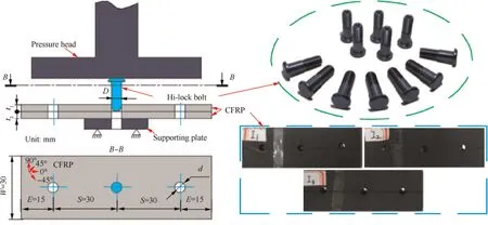
Fig. 1 Geometric details of CFRP/CFRP interference fit bolted joints.

Table 1 Interference fit size details for bolt insertion tests.
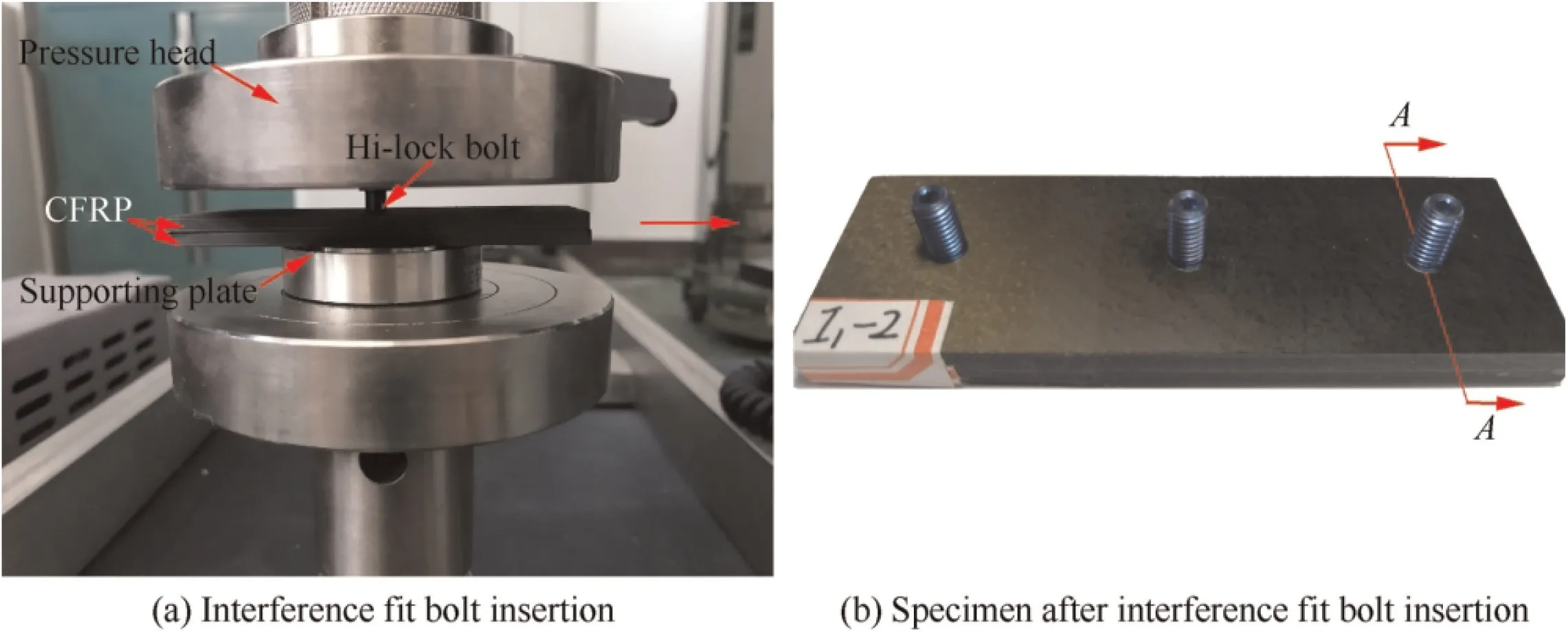
Fig. 2 Bolt insertion progress of CFRP/CFRP interference fit bolted joints.
2.2.2. Testing progress
The progress of quasi-static tensile tests is depicted in Fig.4(a).All specimens were tested on a WDW 100KN material testing machine at room temperature.The constant displacement rate was 1 mm/min during tensile loading progress until the specimen failed. Three repeated tests were performed for each group of interference fit size. A high-resolution X-ray micro-CT scan was used to detect internal damages in the upper laminate of the specimen after joint failure.
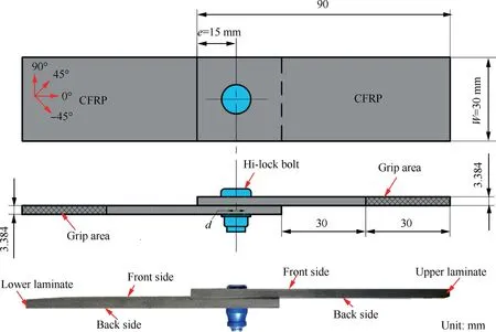
Fig. 3 Schematic of specimens in both quasi-static tensile and fatigue tests.
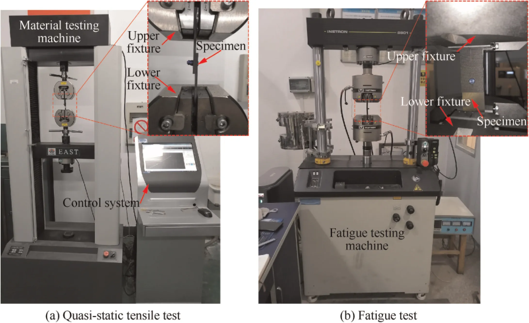
Fig. 4 Mechanical property testing of joints.
The details of fatigue testing progress are illustrated in Fig. 4(b). All the specimens were performed under cyclic tension–tension loads in an INSTRON-8801 fatigue testing machine with stress ratio R = 0.1 and frequency f = 5 Hz at room temperature. Two loading levels were considered for each group of interference fit size, which were based on load–displacement responses of specimens with interference fit size I0 in quasi-static tests.Here,the loading level with a maximum load of 7000 N (0.68 times of the average failure load corresponding to I0 in Section 3.2.1) represented the high loading level, and the loading level with a maximum load of 6700 N(0.65 times of the average failure load corresponding to I0 in Section 3.2.1) represented the low loading level. For each group of interference fit size, three tests were repeated.
3. Results and discussion
3.1. Interference fit bolt insertion
3.1.1. Insertion resistance
The resistance during interference fit bolt insertion is the main reason for ply delamination in joints, and a high insertion resistance can even lead to the failure of interference fit bolt insertion. The insertion resistance Fincludes two parts:

where Fis the shear resistance caused by elastic and plastic deformation of the hole caused by interference fit bolt insertion; Fis the friction force caused by relative movement between the bolt and the hole wall.
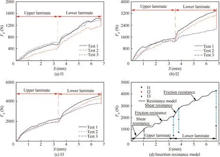
Fig. 5 Insertion resistance-insertion displacement responses.
As shown in Fig. 5, the insertion resistance Fcould be obviously divided into two stages corresponding to upper laminate and lower laminate,respectively. Two stages of insertion resistance–insertion displacement curves were similar: the shear resistance Fwas the domination resistance in the beginning and increased linearly; however, with the insertion displacement increasing, the friction resistance Fbetween the bolt and the hole wall was dominated in the resistance and increased wavily. Both the shear resistance Fand the friction resistance Fincreased rapidly with the interference size increasing from I1 to I3, for example, the average shear resistance and the average friction resistance of upper laminate,respectively, increased from 270 N to 1037 N and from 240 N to 1063 N. Particularly, the slope of shear resistance curve of the lower laminate was larger than that of the upper laminate,which was likely due to that the contact area between the laminates limited the expansion of the hole in the lower laminate.Moreover,as was expected,the peak of the insertion resistance raised obviously when the interference fit size increased, however, the insertion resistance-insertion displacement responses were still similar for all interference fit sizes.The model of the insertion resistance–insertion displacement curve was drawn in Fig. 5(d).
3.1.2. Insertion damage
The hole exit in joints tends to damage during interference fit bolt insertion. Fig. 6 shows the typical experimental results of three interference fit sizes after bolt insertions. Damages occurred around the hole exit of the lower laminate for I1–I3, mainly including fiber and matrix bearing fracture. However, those damages were local and minimal due to the supporting of the metal plate, and the reported serious damages under large interference fit size were not observed.Here,to decrease the hole exit damage, a supporting plate is suggested during bolt insertion.
Internal micro damages of specimens after bolt insertions can be seen in Fig. 7. The hole entrance in upper laminate and the laminate boundary near the hole wall were observed to be the most critical region for damages due to the poor constraint condition of the ply, which were dominated by bearing deformation, fiber/matrix debonding, and ply cracking. With the metal plate supporting, no obvious damage was observed in the hole exit of lower laminate, especially, delamination in laminates did not occur under the experimental conditions.Moreover, for I1, only bearing deformation occurred on the laminate boundary near the hole wall, which was likely to be caused by bearing force and insertion resistance. However,when interference fit size increased to I2 and I3, more serious bearing deformation were observed. At the same time, fiber/matrix debonding occurred on the laminate boundary near the hole wall, and plies near the hole entrance in upper laminate cracked due to the bearing force caused by interference fit. Besides, the entire hole surface observations of both upper and lower laminates after interference fit bolt insertion were similar for all the interference fit sizes. Here, matrix plastic deformation occurred on the hole surface, typically, the hole surface observation of the specimen after interference fit bolt insertion, which is corresponding to I3, was shown in Fig. 8.

Fig. 6 Insertion damages of hole exits corresponding to I1, I2 and I3.
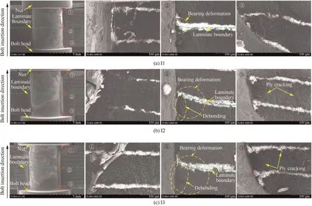
Fig. 7 Internal damages of specimens after interference fit bolt insertions.

Fig. 8 Typical hole surface observation of specimen corresponding to I3 after interference fit bolt insertion.
3.2. Quasi-static tensile properties
3.2.1. Load-displacement response
Based on bolt insertion tests, quasi-static tensile behaviors of joints were tested. Note from Fig. 9 that, load–displacement curves were similar for almost all the specimens corresponding to bolt failure mode,except one corresponding to shear failure mode. The load increased rapidly with the displacement until reaching a peak value,and then exhibited a sudden falling corresponding to bolt failure. Finally, the load decreased wavily corresponding to laminate progressive failure. Particularly,for I0–I2, short wavy stages caused by bearing failure in laminates were observed before peak loads on load–displacement curves. It was indicated that bearing failure occurred in laminates before the final bolt failure. Those could be further evidenced by that an obvious ply bearing deformation occurred on the laminate surface near the bolt head (see Section 3.2.3),and the obvious noise of fiber bearing failure was also heard before bolt failure. However, when interference fit size increased to I3, the short wavy stage disappeared. This indicated that the bolt failed before the laminate bearing failure,which was likely due to the stress concentration factor reducing of the laminate hole for the bolt-hole contact condition improving.Here,defines the failure load as the maximum load before bearing failure for I0–I2,and the maximum load for I3.The displacement corresponding to the failure load was the failure displacement. It could be further found that, though it was shown in Section 3.1.2 that the more serious damages could be caused by the larger interference fit sizes during the bolt insertion, interference fit size exhibited few influences on both failure displacement and failure load of joints under quasi-static tensile loads.
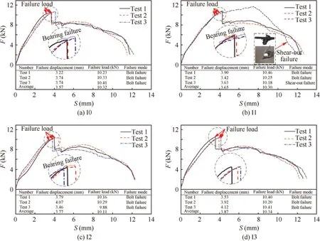
Fig. 9 Load-displacement responses of specimens.
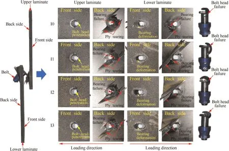
Fig. 10 Failure modes of specimens after quasi-static tensile testing corresponding to I0, I1, I2, and I3, respectively.
3.2.2. Tensile failure mode
Specimens after the quasi-static tensile testing for I0–I3 are illustrated in Fig. 10. The failure mode of the specimen was similar. Almost all the specimens failed in bolt head failure mode caused by secondary bending of joints, while only one specimen failed in shear-out failure mode (see Fig. 9(b)). Bolt head penetration occurred on the front side of upper laminate,and serious bearing deformations were observed on the front side of lower laminate.Moreover,bearing failure and ply tearing occurred on the back side of both upper laminate and lower laminate. Interference fit size seemed to have influence on final failure mode of the specimen, however, the evidence is not sufficient to support this.
The typical internal damage behaviors of the upper laminate of the specimen are further shown in Fig.11.A lot of fiber and matrix fractures were observed in bearing region due to the bearing load, and on both sides of the bearing region,delamination and matrix cracking occurred. The damages in plies near the back side of the laminate were more serious than those in plies near the front side of the laminate due to that the secondary bending of the joint caused the bolt bending leading a higher bearing load on plies near the back side.Besides,note that fiber and matrix fractures occurred in pies near the back side from CT-scan section ⑧and ⑨, while delamination was mainly observed between plies near the front side. Here,during the bearing failure of the joint, it can be indicated that delamination and matrix cracking occurred first in the bearing region.Then,further damage modes including fiber and matrix fracture occurred due to the increasing load. Finally, internal damages propagated from bearing region to two sides at the same time.
3.2.3. Tensile failure progress
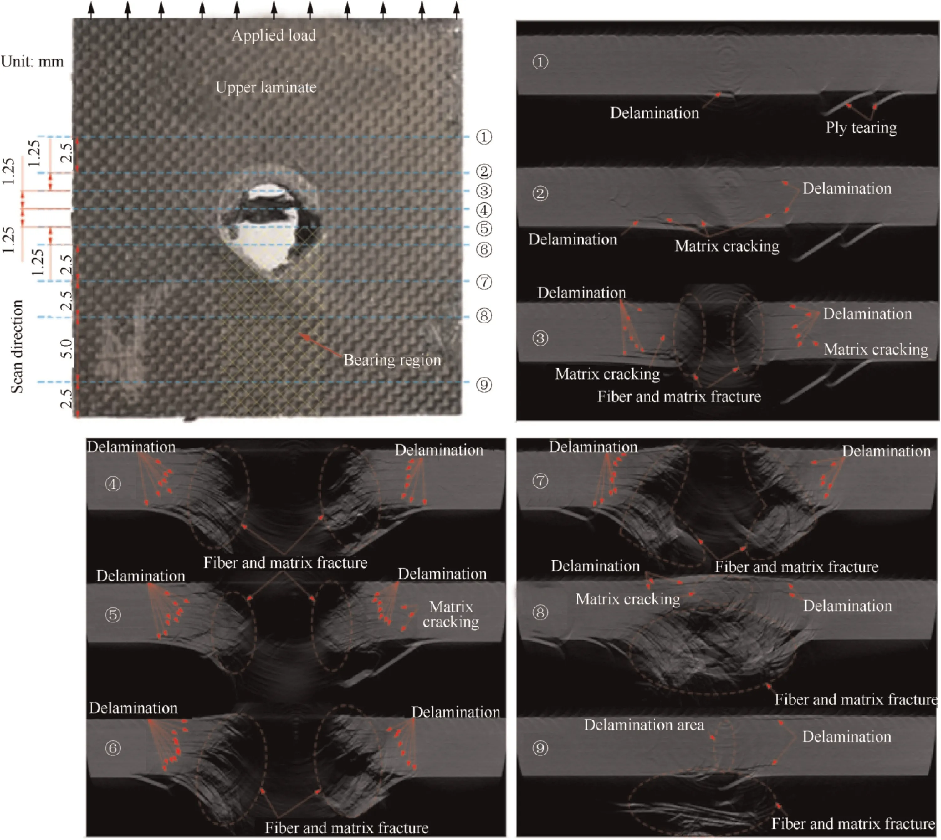
Fig. 11 CT-scan sections for upper laminate of specimen corresponding to I3 after quasi-static tensile testing.
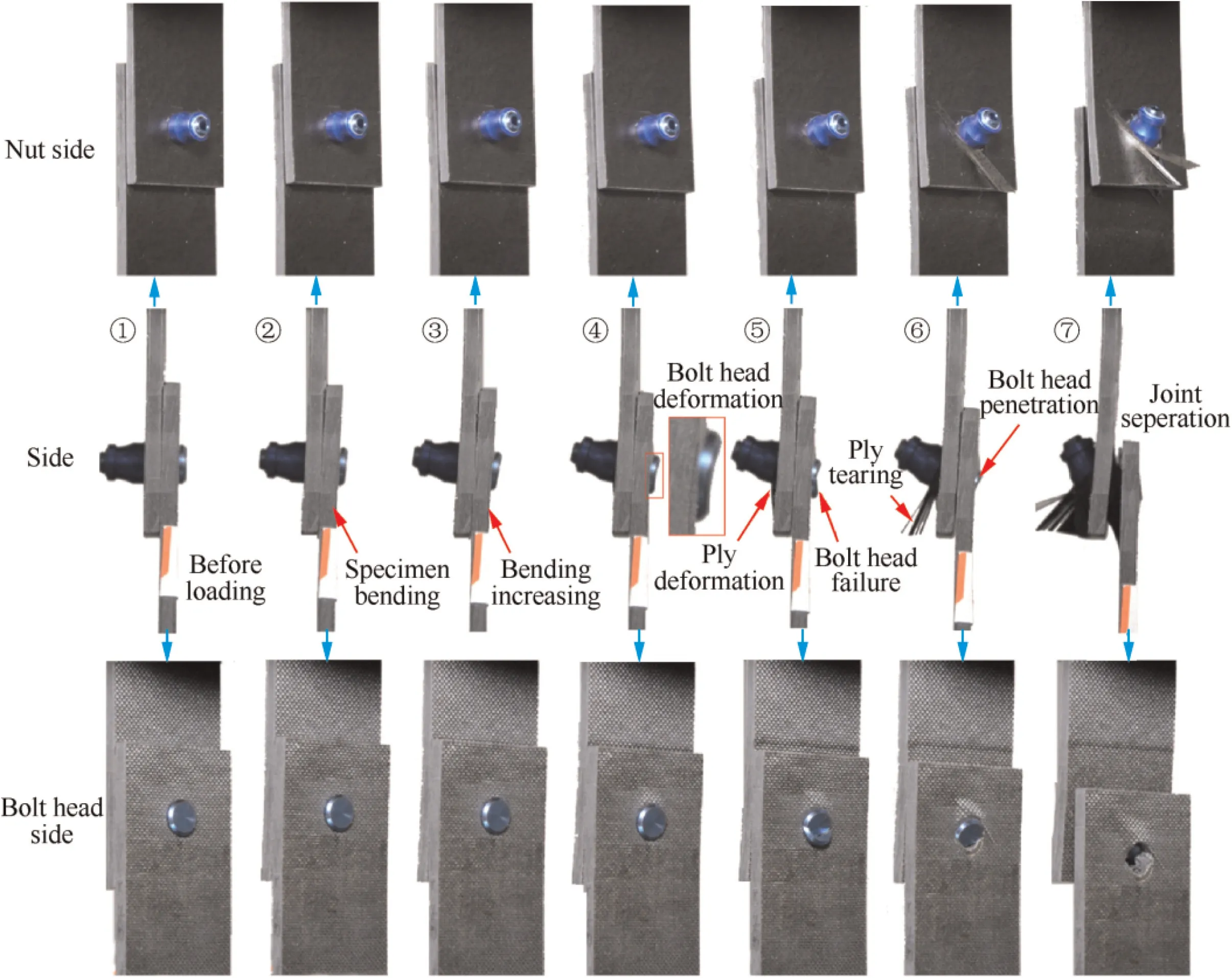
Fig. 12 Typical failure progress of specimen corresponding to I3 during quasi-static tensile testing.
The influence of interference fit size on specimen failure progress of the specimen was not obvious. The failure progress of the specimen was similar for I0–I3 just like the final failure mode of the specimen.This is probably due to that interference fit changed local bolt-hole contact condition and has an obvious influence on local stress around the hole under quasi-static loads; however, this influence is local and is not obvious for entire specimen. To further understand joint mechanical behaviors, Fig. 12 shows the typical failure progress of the specimen. The failure progress of the joint could be divided to seven typical stages. In initial stages, the joint bending occurred and increased obviously with the increasing load.The secondary bending of the joint cause the bolt bending,leading to a raising in the contact force between bolt head and front side of the upper laminate. Then, an obvious bolt head deformation was observed. When the external load reached a critical value, the bolt head failed, and the first ply near the hole on the back side of lower laminate deformed corresponding to internal bearing failure. With the loading, bolt head penetration and ply tearing were observed. Finally, the joint final separation occurred.
3.3. Fatigue properties
As was expected, the fatigue life of joints could be obviously enhanced by interference fit in comparison to net fit (I0), as shown in Fig. 13, where N(i = 1, 2, 3) is the average fatigue life corresponding to specimens of Ii (i = 1, 2, 3), Nis the average fatigue life corresponding to specimens of I0, especially at I1 representing the low interference fit level.However,the inadequate interference fit size, typically like I3, exhibited few influences in increasing fatigue life, and even decreased the fatigue life under the low loading level. Furthermore, for different loading levels, the increasing in fatigue life of joints corresponding to the same interference fit size was varied.Specially,for I2,the fatigue life was close under both the high and the low loading level, and the fatigue life corresponding to I3 under the low loading level was a little lower than that under high loading level. Here, considering the fatigue life dispersivity of the specimens and that the low loading level (6700 N)and the high loading level (7000 N) were close, the fatigue life for I3 was considered similar under both the high and the low loading level. However, the reason why the fatigue life was similar under both the high and the low loading level for I2 and I3 was not clear. Since the fatigue failure of specimens was dominated by bolt failure, it was likely due to that interference fit changed the stress distribution and stress amplitude of the bolt during the external loading,which will be analyzed in further simulation work.
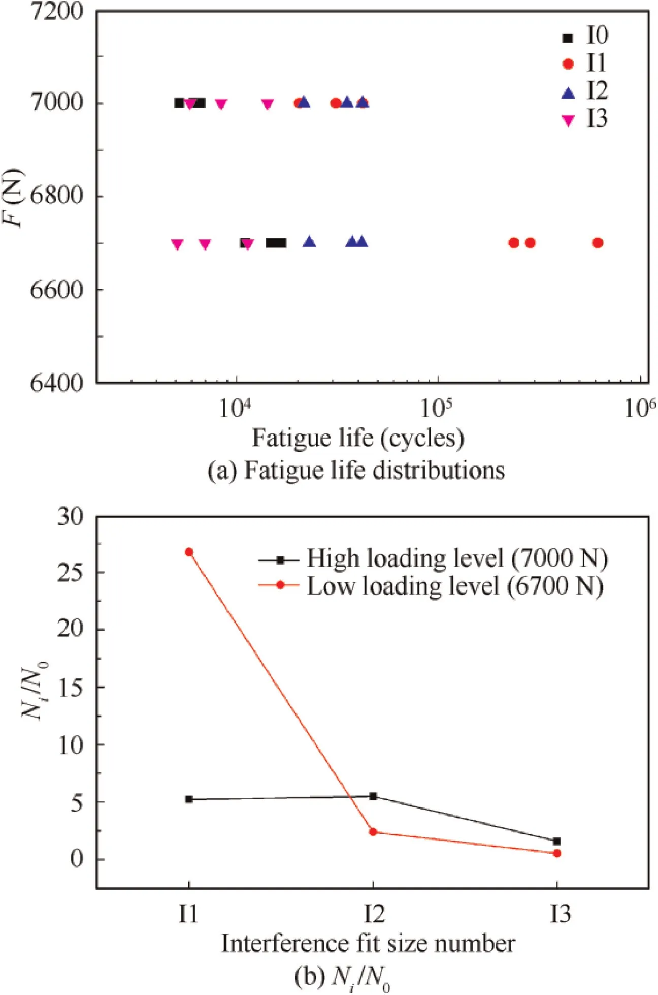
Fig. 13 Fatigue life of specimens under high and low loading levels.
Fatigue failure modes for I0–I3 corresponding to the high and low loading levels were quite similar(see Fig.14).The bolt failure mode with bolt head failure dominated the specimen failure for I0, and ply cracking was observed on the back side of the lower laminate. However, for I1–I3, all bolts failed at bolt shank near the front side of the upper laminate. Though bearing damages were observed in upper laminate,those damages were more likely to be caused by the fracture bolt shank after bolt fatigue failure,and no ply cracking was found on the back side of the lower laminate. The results suggested that interference fit could improve the fatigue resistance of the laminate hole, however, the bolt seemed to suffer a more critical local fatigue loading condition due to the transferring stress changes caused by interference fit. Moreover, all specimens were dominated by bolt failure mode under the testing condition. However, the influence of bolt insertion damages on the fatigue behaviors of joints was not obvious.
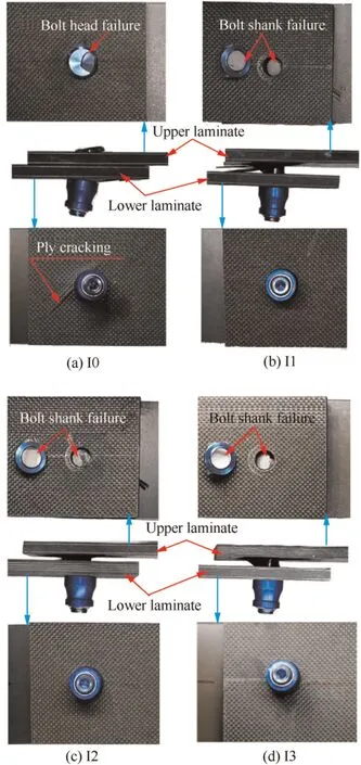
Fig. 14 Typical failure modes of specimens after cyclic loading corresponding to high loading level.
3.4. Discussion
Under the experimental conditions proposed, bolt insertion damages in CFRP/CFRP interference fit bolted joints are observed.The influence of those damages on joint final failure seems minimal under both quasi-static loads and fatigue loads.However, this result is limited by bolt failure mode in tests.Stronger bolts will be used in the further study. Moreover,the influence of bolt insertion damages on failure initiation and propagation is still unknown, and additional investigations are required.
4. Conclusions
(1) During the interference fit bolt insertion, the hole entrance in upper laminate and the laminate boundary near the hole wall were observed to be the most critical regions for damages. The larger the interference fit size,the more serious damages.With the metal plate supporting, local minimal fiber and matrix bearing fractures occurred around the hole exit of the lower laminate,especially, delamination in laminates did not occur under experimental conditions.
(2) Load–displacement curves of all specimens except one were similar in quasi-static tensile tests. For small interference fit sizes, bearing failure occurred in the laminate before final bolt failure; however, with the increasing of the interference fit size,the bearing capability of the laminate hole increased leading to the bolts failed first.Though the more serious damages were caused by the larger interference fit sizes during the bolt insertion,the influence of interference fit sizes on both failure displacements and failure loads of joints was minimal.
(3) In quasi-static tests, secondary bending exhibited a significant influence on joint finial failure. Combinations of multi failure modes were observed in joints,including bolt failure, bearing failure, and shear-out failure. The bearing region of the laminate was dominated by fiber and matrix fractures, while damages in the two sides of the bearing region were mainly delamination and matrix cracking. Moreover, delamination and matrix cracking seemed to occur early, following by fiber and matrix fracture. Finally, internal damages propagated from the bearing region to two sides.
(4) The fatigue life of joints could be obviously enhanced by the proper interference fit. The fatigue life increasing corresponding to the same interference fit size was varied under different loading levels. Bolt head failure dominated the joint fatigue failure mode for I0,while all bolts failed at the bolt shank for I1–I3. Interference fit could improve the fatigue resistance of laminate hole; however, the bolt seemed to suffer a more critical local fatigue loading condition. Moreover, the influence of bolt insertion damages on joint fatigue failure was not obvious.
The authors declare that they have no known competing financial interests or personal relationships that could have appeared to influence the work reported in this paper.
This work was funded by China Postdoctoral Science Foundation (No. 2020M673227), NSAF, China (No. U1830122), and Sichuan Science and Technology Program, China (No.2020YFG0109).We would like to thank the Analytical&Testing Center of Sichuan University for the help in SEM images.
