Deployment of SMP Miura-ori sheet and its application: Aerodynamic drag and RCS reduction
Ji ZHANG, Changguo WANG, Lamei ZHANG
a National Key Laboratory of Science and Technology on Advanced Composites in Special Environments, Harbin Institute of Technology, Harbin 150080, China
b Center for Composite Materials and Structures, Harbin Institute of Technology, Harbin 150001, China
c Department of Information Engineering, Harbin Institute of Technology, Harbin 150001, China
KEYWORDS Aerodynamic characteristics;Deployment;Miura-Ori;Morphing aircraft;RCS reduction;SMP sheet
Abstract Origami,such as Miura-ori,is the art of folding two-dimensional materials into complex,elaborate, and multifunctional three-dimensional objects. In this paper, SMP MO sheet are prepared, and the accuracy of deployable process is verified by experiments. The folding and deployable process of SMP MO sheet is divided into 4 stages, and each stage is described in detail. The stiffness of smart deployable stage is characterized by an exponential decline at the beginning and a gradual decrease to 0, and this is similar to the theoretical shear equivalent modulus in the Y direction. The effects of various parameters on strain and stress are also explored. The purpose of studying these mechanical characteristics is to provide driving force reference in application; In terms of application, the flow field and electromagnetic characteristics of MO sheet in different directions are studied. The aerodynamic drag and RCS reduction of MO unit cell and graded MO sheet during the deployable process are evaluated. When the dihedral fold angle is about 45°,the RCS reduction and drag reduction characteristics of MO sheet are relatively optimal,which is most beneficial to morphing aircraft.
1. Introduction
At present, civil and military fields have put forward higher requirements for aircraft.The new generation of aircraft can always maintain good performance in changing flying environments (altitude, Mach number, etc.) and performing various tasks (take-off and landing, cruise, maneuvering,hovering,attack,etc.).Aircraft with a fixed shape cannot meet this requirement.The morphing aircraft adapts to different flying environments by changing its shape, improving aerodynamics and electromagnetic stealth characteristics.The driving formsof morphing aircraft mainly include mechanical drive,inflatable drive, and smart drive (smart materials). Compared with mechanical and inflatable drive, smart drive can obtain higher precision,high storage rate,good deployable controllability,low bulk density.According to the scale,the variants are divided into three categories. One is large-scale variants,including wingspan length, changes in airfoil shape, etc., the second is medium-scale variants, including airfoil bending,thickness changes, etc., and the third is small-scale variants,including local deformation and bulging to affect the local flow field and electromagnetic characteristics of the aircraft.
In recent years, the interest in Shape Memory Polymers(SMP) and origami has increased for aerospace applications.Miura-Ori (MO) is a typical form of origami and is gaining popularity in research.At present, the research on MO is mainly focused on the prediction of equivalent elastic modulusand mechanical properties. However, the research on deployment behavior of the SMP MO sheet is limited.With the rapid development in morphing aircraft,the drag reduction technique has also received widespread attention.Grooves is one of effective techniques to reduce the drag of aircraft.The design principle of stealth aircraft is to avoid radar reconnaissance through changes in shape and materials.The Radar Cross Section(RCS)is a measure of the power returned or scattered in a given direction based on the concept of isotropic scattering of a target under plane wave incidence. RCS is 4π times the ratio of the scattered power at the receiver to the power density of the incident wave on the target per unit solid angle. RCS reduction, that is, realizing the so-called‘‘stealth”, can in general be obtained in two ways: shaping of the object and application of Radar Absorbing Materials(RAM)or coatings,which can absorb, dissipate, and interfere with the electromagnetic (EM) waves emitted by the radar,making them unable to receive reflected EM waves.How to solve the contradiction between stealth and aerodynamic performance of aircraft has received great attention.Morphing aircraft involves a wide range of disciplines, and there are many problems to be solved, and various problems are coupled with each other, such as aerodynamic mechanism research,structural design,and electromagnetic stealth.Therefore, the development of variant aircraft should adopt a method of dispersing difficulties, making breakthroughs and advancing each other.
The deployable process of SMP MO sheet are studied and preliminary design calculations are carried out,focusing on the analysis of the mechanical characteristics; The purpose of studying these mechanical characteristics is to give driving force reference in application; MO can realize threedimensional space and the change of projection area in different directions; Considering the drag reduction and stealth of the aircraft, the reflection wave of the structure shape and the wave absorption of the resonance rings combine to achieve the stealth effect;However,the stealth design changes the surface geometry and topography,which in turn affects the aerodynamic drag of the flight. Therefore, it is necessary to combine the two aspects to design drag and RCS reduction at the same time.
2. Theory and method
2.1. Constitutive model of SMP sheet
In order to describe the deformation properties of polymers,viscoelastic model is used. Thermal expansion is also considered in the model and assumed to be independent of the mechanical behavior.In this model, the stress-strain relationship and creep strain ε-creep irrecovery strain εrelationship are expressed as follows:

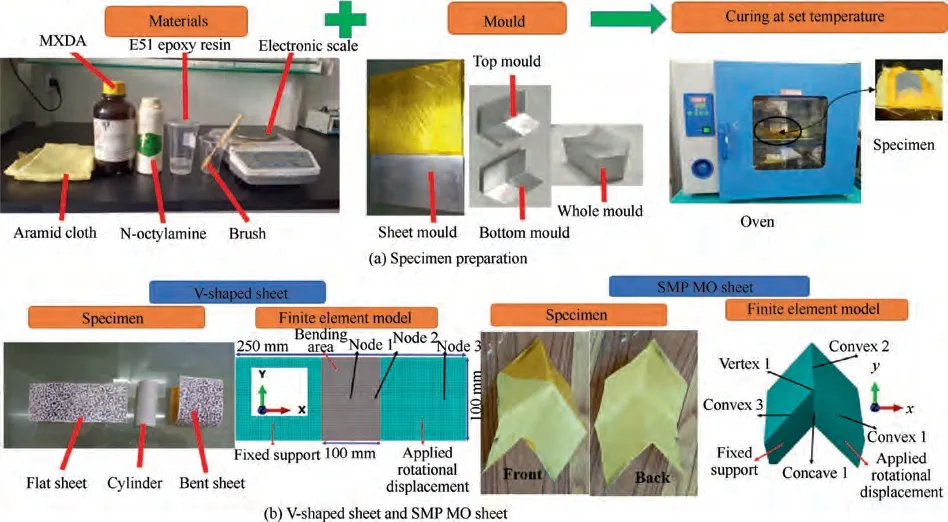
Fig. 1 Fabrication process of SMP sheet.
σ, ε and T denote stress, strain and temperature, respectively; The dot denotes time derivative;E, μ,λ, and α represent elastic modulus, viscosity, retardation time and coefficient of thermal expansion; A certain ratio C and the critical strain εdepend on temperature.
When applied to polymers, glass transition temperature Tis usually used as the reference temperature. The specific form of the time-temperature equivalent equation is described as:

where Ais the transformation function. C,Care the constants.
In this paper, the long-term relaxation modulus is 1.67 MPa, Poisson’s ratio is 0.4, and the thermal expansion coefficient is 6.47×10. Tis 78℃, Cis 15.6, and Cis 32.6.The parameters of each discrete term of Prony series are substituted.
The folding and deployable process of the model is divided into four stages: folding stage under external load (Stage 1),cooling stage (Stage 2), unloading stage (Stage 3) and heating recovery stage (Stage 4, smart deployable stage). In Stage 1,the temperature increases above T, and rotational displacement is applied to make the model fold along the crease. In Stage 2, the temperature decreases below T. In Stage 3, the external load is withdrawn. In Stage 4, the temperature increases to above Tagain,and the model is gradually deployable due to the shape memory effect of SMP.
2.2. Fluent method
For the turbulent motion of the incompressible fluid, the Reynolds-Averaged Navier-Stokes (RANS) equations are commonly used method. The equation of motion of incompressible Newtonian fluid is averaged (expressed by 〈〉) term by term, and RANS equations are expressed as
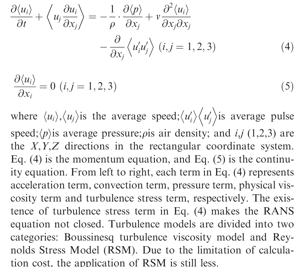
The Spalart-Allmaras (S-A) one-equation model could get reasonable results for a wide range of flow problems and is quite popular in aerospace. Fluid parameters are selected at a height of 20 km (density ρ= 0.08891 kg/m, dynamic viscosity coefficient u=1.4216×10kg/(m·s)). The pressure velocity coupling is combined with Semi-Implicit Method for Pressure-Linked Equations Consistent (SIMPLEC) algorithm and Pressure Implicit with Splitting of Operators(PISO)algorithm.For relatively simple problems,the SIMPLEC algorithm can quickly get a convergent solution. In each iteration of the PISO algorithm, the velocity values of adjacent grids will adopt the latest velocity prediction value. The iterative residual errors of all variances in the governing equations are set as 1×10.
A three-dimensional model of the flow field is established.The direction of the wind is flowing from the left to the right(or from up to down). In the left (or up) plane of computational domain (cuboid), the velocity inlet is adopted, and the flow velocity is 10 m/s. The setting condition of the right (or down) plane is the pressure outlet. The model surface is set to non-slip wall constraints (Wall: no slip), and the walls around the calculation domain are set to slip constraints(Wall:specified shear, symmetry).
2.3. Electromagnetic calculations
Electromagnetic calculations use Method of Moment (MoM)and the essence of MoM is to transform a functional equation into a matrix equation, which is solved by matrix inversion or other methods of solving linear equations. The linear vector space sum operator is expressed as follows

where L-Differential or integral operator;f-Field or response;g-Source or incentive.
MoM is to discretize the continuous equations described by Eq. (6) into algebraic equations, so as to use numerical methods to find approximate solutions. The accuracy of the MoM calculation method of FEldberechnung bei Korpern mit beliebiger Oberflache (FEKO) software is verified by performing monostatic or bistatic RCS calculations on the metal sphere,squat cylinder and dihedral corner, and comparing with their experimental,Finite Difference Time Domain(FDTD)or analytical solutions. In this paper, plane wave incidence is adopted, and the incidence frequency is 1-10 GHz.
3. Fabrication of SMP sheet and strain tests
Fabrication process of SMP sheet is shown in Fig.1(a).Firstly,the SMP resin is formulated from M-xylylene diamine(MXDA), N-octylamine and E51 epoxy resin. Suppose the weight of the aramid cloth is m, and the mass percentage of epoxy resin is 40%, and the amount is 2/3m. The amount of MXDA is 0.296055 times the amount of epoxy resin. The amount of N-octylamine is 0.01734 times the amount of epoxy resin. Then, the aramid cloth is coated with SMP resin and is placed between the top and bottom mould. Finally, the specimen can be fabricated after heating and curing in the oven.As shown in Fig. 1(b), for V-shaped sheet (is abbreviated as sheet),the sheet’s length direction is the X direction,the width direction is the Y direction,and the thickness direction is the Z direction. For MO sheet, the X and Y directions are shown in the figure,and the Z direction is along the thickness direction.
Vic-3D testing system based on non-contact digital image correlation technologyis used to measure the strain during the deployment of sheet. Curves of strain with deployable angle are shown in Fig. 2(a), the strain at the center point(Node 1)is extracted,and the experimental results are in good agreement with the simulation results,which verified the reliability of Finite Element Method (FEM). Strain-temperature curves are shown in Fig. 2(b), it is found that the nodes near the crease area showed larger strain, and the strain (E) in the X direction is much larger than the strain (E) in the Y direction. Therefore, it is important to analyze the nodes at the crease area.
4. Results and discussion
4.1. Deployable process and equivalent modulus prediction of SMP MO sheet
Based on FEM of SMP sheet above, the model of SMP MO sheet is established and its deployable process is studied. The boundary condition is: fix one surface of the MO sheet and apply a rotational displacement on a non-adjacent surface.As the rotational angle increases,the model gradually changes from the deployable state to the folded state or from the folded state to the deployable state. Fig. 3 illustrates the deployable process of SMP MO sheet in different times,and the simulation result shows good agreement with the experimental results.
The MO unit cell in our design is composed of four identical parallelograms that are connected by three convex mountain and one concave valley creases. The strain in this paper adopts the logarithmic strain components in the direction of the rotation. Strain and stress in the X direction are used at concave 1, vertex 1 and convex 2, and strain and stress in the Y direction are used at the convex 1 and the convex 3.
Strain-temperature curves are shown in Fig.4(a),it is found that the strain at the concave valley crease is always larger than that at the convex mountain crease.In order to make the result more obvious,the strain and stress of the node at the concave valley crease is analyzed. Stress and strain-temperature curves and Stress-strain curve are shown in Fig.4(b)and(c).In Stage 1,the material is in the state of axial tension,and the stress and strain gradually increase. In Stage 2, the specimen is still in a constrained state, so the strain remains unchanged. As the temperature decreases, the specimen shrinks, the material modulus increases, and the stress increases. In Stage 3, when the specimen is unloaded at a low temperature, the material modulus increases and specimen shrinks in the glass state, so a small amount of ‘rebound’ occurs. The strain resilience is 0.25%and the model shows a reverse bending state and negative stress occurs.In Stage 4,with the decrease of temperature,the specimen is in the shape recovery stage, and the stress and strain return to the initial state.
In order to predict the equivalent modulus of SMP MO sheet in different deployable states, the single cell model and parameters in Ref.are adopted.First,the model is equivalent to a homogeneous sheet with the same thickness (0.5 mm).Then,the energy balance principle is used to obtain the equivalent elastic modulus.
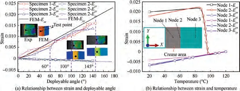
Fig. 2 Deployable process of SMP sheet.
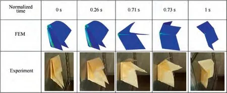
Fig. 3 Deployable process of SMP MO sheet.
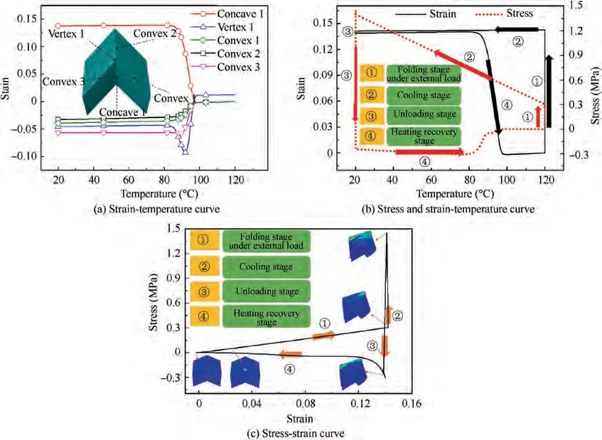
Fig. 4 Relationship between temperature, stress and strain.
Compression modulus Ein Z direction,shear modulus Gin the X direction, shear modulus Gin the Y direction, and the critical buckling load Pof Z direction is expressed as

where a and b are a parallelogram’s sides;γ is acute angle; θ is the dihedral fold angle between the facets and the XY plane;ξ and ψ are angles between fold lines and the X axis and φ are dihedral angles between facets and the XZ plane, respectively.H,S and L are outer dimensions;υ is Poisson’s ratio; t is the thickness of the sheet; μ is the length factor.
As shown in Fig. 5(a), a = b = 282.8 mm,γ = 45°,t=10 mm,θ=45°(15°,30°,60°,75°).With these parameters,the geometric configuration of MO can be completely determined, and then arrayed to obtain MO sheet with different number of unit cells. When γ = 90°, the MO sheet is a Vshaped sheet.
Because MO can be folded and deployed, it realizes the change of three-dimensional space and projection area in different directions; With the change of the dihedral fold angles θ,the corresponding vertical(S)and horizontal(S)projection areas change as shown in Eq. (11) and Eq. (12); As θ increases, Sis a monotonically decreasing function; Sis a function that first increases and then decreases.

Equivalent elastic modulus and buckling load-dihedral fold angle θ curves are shown in Fig.5(a)and(b),with the gradual deployment of specimen, the prediction of equivalent shear modulus in the Y direction is similar to the recovery process in Stage 4.Therefore,equivalent shear modulus in Y direction could be used to approximate the performance trend of recovery process of specimen.
4.2.The influence of various parameters on the smart deployable process
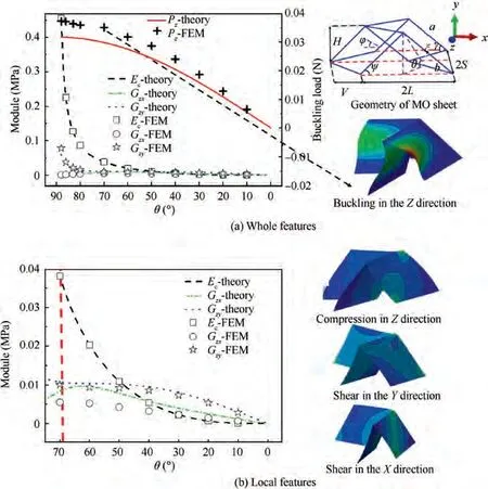
Fig. 5 Equivalent elastic modulus and buckling load-dihedral fold angle curves.
The influence of various parameters on the strain and stress are shown in Fig. 6, the results show that the change of the three parameters(thermal expansion coefficient,Poisson’s ratio,and Elastic modulus)have little effect on the strain,but great influence on stress in Stage 2 and Stage 4. The time-temperature equivalent equation constant results in the change of the relaxation time of Stage 4, so it is the key parameter to control the equivalent conversion of temperature and time. As the thickness increases, the stress and strain gradually increase, but the trend is consistent; thickness is the most sensitive to the whole smart deployable process.
4.3. Electromagnetic and aerodynamic characteristics of MO unit cell
At present, in response to the requirements of aircraft stealth and aerodynamic characteristics, morphing MO sheet is proposed. This paper provides innovative solutions for the structure optimization of aircraft stealth and aerodynamic characteristics. As shown in Fig. 7, the electromagnetic and flow field models are established. The inflow direction of the wind and the incident direction of the electromagnetic are from the left (up) direction. The results of monostatic and bistatic RCS and aerodynamic characteristics of MO unit cell are compared, and it is found that the MO sheet has own advantages and characteristics. The work done in the previous period,such as Ref., has carried out a detailed exploration of the electromagnetic properties of the origami-based metasurfaces.After research, graded MO metasurfaces are proposed, which satisfies the optimal flow field and electromagnetic characteristics during the deployable process. The unit cells of different sizes in the gradient composite MO can not only maintain the electromagnetic and flow field characteristics of the unit cell,but the small unit cell can also improve the strength,stiffness, and stability of the structure. The combination of large and small cells can form a kirigami configuration,and the formation of holes is beneficial to reduce the weight of the structure. For the graded MO sheet, its geometric structure is composed of many different sizes of MO unit cells (parameter b increases by integer multiples); the electromagnetic and flow field characteristics of this graded structure are analyzed.
As shown in Fig.8,the RCS characteristics of the MO unit cell with the dihedral fold angle of 45°and the V-shaped sheet are compared. For monostatic RCS, the incident frequency is 1-10 GHz. When incident from up direction, the RCS of MO unit cell and sheet are similar. When incident from the left direction, the RCS of MO unit cell is lower than that of the sheet, which shows that the MO sheet has advantages in this direction. Fig. 8 (b), (c) and (d) show the bistatic RCS of the MO sheet and V-shaped sheet under different paths (path 1,path 2 and path 3)at a frequency of 5.35 GHz.Path 1 is a horizontal cut, and paths 2 and 3 are vertical cuts. As shown in Fig. 8(b), the RCS of MO unit cell in this path is higher than that of sheet,which is caused by the complicated configuration of the MO sheet in the horizontal cut. As shown in Fig. 8(c),the RCS of the MO unit cell in this path is generally lower than that of sheet. As shown in Fig. 8(d), when the dihedral fold angle is small, the RCS of the MO sheet is larger relatively,and when the angle is larger and larger, the RCS is reduced more obviously.
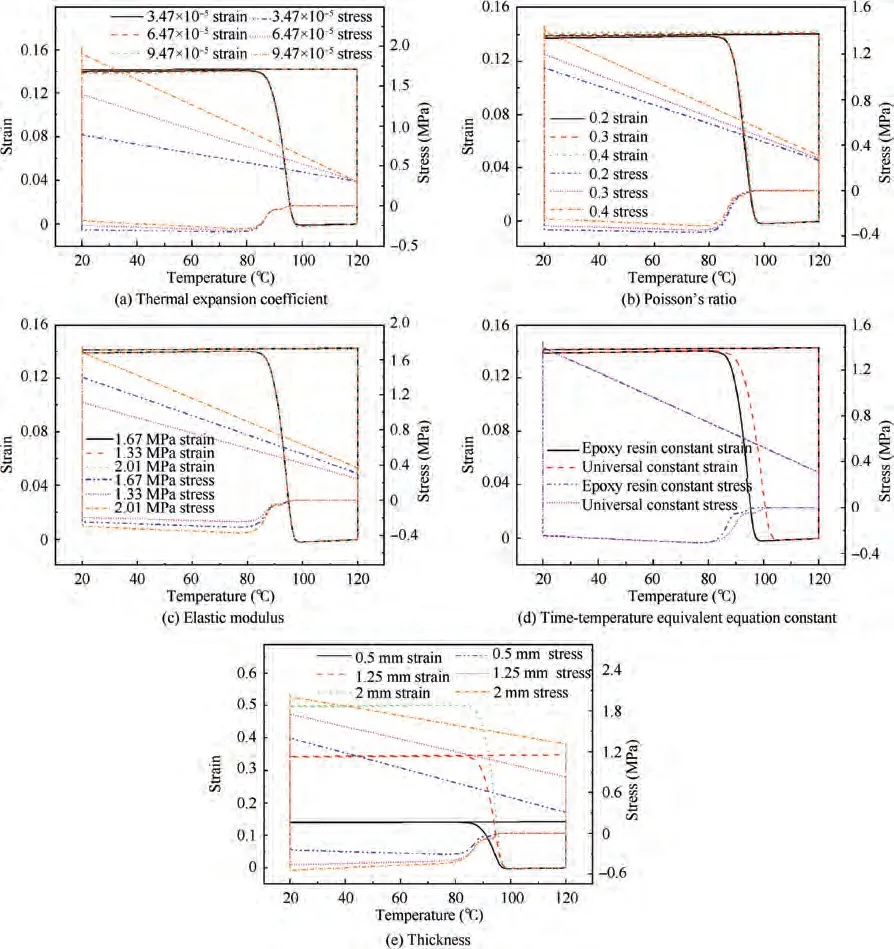
Fig. 6 Influence of various parameters on the stress and strain.
In general, the reduction of RCS in one direction comes at the cost of an increase in RCS in the other direction.However,the MO sheet has better RCS reduction characteristics because it is spliced by a V-shaped sheet,which increases the probability of reflecting electromagnetic waves.
As shown in Fig. 9, electromagnetic waves are incident from the up and left ends of the MO sheet respectively, and the electromagnetic characteristics in different directions are studied. When incident from the up direction, it is found that as the model is gradually folded (the dihedral fold angle θ is from 0°to 90°),the magnitude of the RCS reduction at different frequencies tends to be stable.This is because the projected area of the model is reduced and the structure changes from plane to surface, from two-dimensional to three-dimensional.When the dihedral fold angle θ is 45°,the RCS of the structure is the lowest, and the configuration at this time is most conducive to RCS reduction. When incident from the left, it is found that as the model is gradually folded, when the frequency is relatively small, the smaller the dihedral fold angle θ, the smaller the RCS. As the frequency increases, RCS is the smallest for model at the dihedral fold angle θ of 45°,which is caused by the reflection of electromagnetic waves by the Vshaped feature.
As shown in Fig. 10, the flow field characteristics of MO sheet are studied. When it flows in from the up direction, the drag force of MO sheet is smaller than that of sheet and the maximum pressure is mainly concentrated at the crease.When it flows in from the left direction, the drag force of the MO sheet is greater than that of sheet and the maximum pressure is concentrated at the lower left position of model.
The aerodynamic drag of MO sheet during deployable process is studied, as shown in Fig. 11. When the wind flows in from the left, the drag force is greatest when the dihedral fold angle is 45°, because the windward area is the largest at this time. When flowing from the up direction, as the projected area decreases, the drag force gradually decreases.
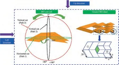
Fig. 7 Electromagnetic and flow field models.
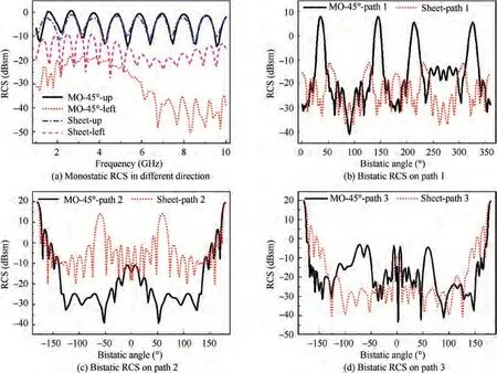
Fig. 8 RCS reduction results of MO unit cell.
4.4.Aerodynamic drag and RCS reduction of graded SMP MO sheet
As shown in Fig. 12, the aerodynamic characteristics of the graded MO sheet are studied, and it is found that it has similar laws to the MO unit cell. When flowing in from the up direction, as the windward area gradually decreases,the drag force becomes smaller and smaller. When inflow from the left, the windward area and drag force of the MO sheet with 45° dihedral fold angle is the largest. The MO unit cell at the back of the model has less influence on drag force and enhance the structural strength, stiffness,and stability.
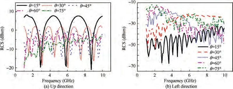
Fig. 9 RCS reduction of MO unit cell during deployable process.

Fig. 10 Aerodynamic characteristics of MO unit cell.

Fig. 11 Aerodynamic drag of MO sheet during deployable process.
As shown in Fig.13,when incident from the up direction,it is found that as the model is gradually folded,the RCS amplitude of different frequencies tends to be stable.When the dihedral fold angle θ is 45°,the RCS of the model is the lowest,and the configuration at this time is most conducive to RCS reduction.When incident from the left,it is found that as the model gradually folds, the RCS becomes smaller and smaller. As the frequency increases, the RCS is always the lowest when the dihedral fold angle θ is 45°. The characteristics of the graded MO sheet is similar to that of the unit cell, and the laws are expansive. In summary, when the dihedral fold angle is 45°,the RCS reduction and drag reduction characteristics of the MO sheet are relatively optimal, which is most beneficial to the morphing aircraft.
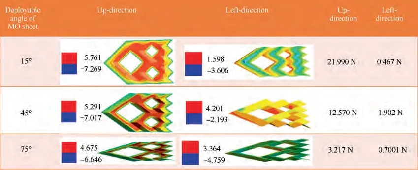
Fig. 12 Aerodynamic characteristics of graded SMP MO sheet.
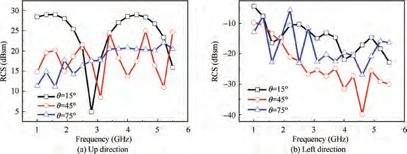
Fig. 13 RCS reduction of graded SMP MO sheet.
5. Conclusions
In this paper, deployment behavior of SMP MO sheet is studied and its coupling characteristics in aerodynamic drag and RCS reduction are evaluated, the following conclusions can be drawn:
(1) The folding and deployable process is divided into four stages.In Stage 1,the stress and strain increase linearly.In Stage 2, the strain does not change and the stress increases. In Stage 3, the material elastic modulus increases and specimen shrinks in the glass state, so a small amount of ‘‘rebound” occurs. The model shows a reverse bending state and negative stress occurs. In Stage 4, the stress and strain return to the initial state.The change of stiffness in Stage 4 is characterized by an exponential decline at the beginning and a gradual decrease to 0, and it is similar to the shear equivalent modulus in the Y direction. Therefore, the shear equivalent modulus in the Y direction can be used to predict the trend of stiffness change in Stage 4(smart deployable stage).
(2) The thermal expansion coefficient, Poisson’s ratio and elastic modulus have little influence on the strain, but great influence on stress in Stage 2 and Stage 4. The time-temperature equivalent equation constant leads to the change of relaxation time in Stage 4.As the thickness increases, the stress and strain gradually increase,but the trend is consistent. Thickness is the most sensitive to the whole smart deployable process.
(3) The aerodynamic drag and RCS reduction characteristics of the MO sheet when electromagnetic wave is incident or wind flows in from the left or up are studied respectively. It is found that projected area in the corresponding direction and the dihedral angle of V-shaped configurations of MO sheet have a greater influence on flow field and RCS. When the dihedral fold angle is about 45°, the RCS reduction and drag reduction characteristics of the MO unit cell and the graded MO sheet are relatively optimal, which is most beneficial to morphing aircraft.
In conclusion, the deployable characteristics of MO SMP sheet are obtained accurately. Through flow field and electromagnetic analysis, it provides guidance for the application of SMP MO sheet in morphing aircraft.
The authors declare that they have no known competing financial interests or personal relationships that could have appeared to influence the work reported in this paper.
The authors gratefully acknowledge the financial support from the National Natural Science Foundation of China (No.11872160) and the Science Foundation of the National Key Laboratory of Science and Technology on Advanced Composites in Special Environments (JCKYS2020603C007).
 Chinese Journal of Aeronautics2022年8期
- Chinese Journal of Aeronautics的其它文章
- Experimental and numerical investigation on opposing plasma synthetic jet for drag reduction
- Ground-based investigations on phase-moving phenomenon with space sublimation cooling for lunar exploration missions
- Novel roll effector based on zero-mass-flux dual synthetic jets and its flight test
- Flow field design and experimental investigation of electrochemical machining on blisk
- Improving performance of macro electrolyte jet machining of TC4 titanium alloy:Experimental and numerical studies
- Numerical investigation of effect of a centrifugal boost impeller on suction performance of an aircraft hydraulic pump
