Flow field design and experimental investigation of electrochemical machining on blisk
Jianwei GUO, Dong ZHU, Di ZHU
College of Mechanical and Electrical Engineering, Nanjing University of Aeronautics and Astronautics, Nanjing 210016, China
KEYWORDS Blisk;Electrochemical machining;Electrolyte;Flow field;Surface quality
Abstract Flow field is a crucial factor to influence the stability and surface quality in the electrochemical machining (ECM) of blisks. A four-way flow mode was proposed to eliminate mixing regions of electrolyte at the leading and tailing edges. Two flow field models were described separately in this report:a W-shaped flow mode and a four-way flow mode.The flow field was analyzed through a finite element method. The results showed that, in comparison with the W-shaped flow mode, the distribution of electrolyte flow was more uniformed and the mixed region in the flow channel was improved.The pressure of the leading and tailing edges inlets was optimized,and optimal pressure of 0.6 MPa was determined.In addition,verification experiments were performed,and the results showed that the stability, efficiency, and quality of the profiles of the blisk blade manufactured by ECM were enhanced in the new flow mode.
1. Introduction
To reduce the weight and enhance the reliability of jet engines,the engine rotor blade and wheel disc have been integrated to form a blisk, which is a component designed to meet the requirements of high-performance aero engines.Electrochemical machining (ECM) is a non-traditional machining technique, which has a high-processing efficiency for machining complex surfaces and intricate shapes from difficult-tocut materials such as titanium-based alloys and nickel-based alloys. In comparison with conventional machining, ECM has many advantages, such as high efficiency, no electrode loss, and no restriction on the mechanical properties of the machined metal.
The flow field is a critical factor in ECM. It affects the machining repeatability, stability, and surface quality. Therefore, the design of a reasonable flow field is the first consideration in ECM. Kang et al. established a three-dimensional model and a computational model of the flow field in a machining process to analyze the flow field characteristics of the inner-spraying spherical cathode to optimize the design of the cathode.Nayak et al. focused on the Computational Fluid Dynamics (CFD) simulation of fluid flow in the interelectrode gap and thermal analysis,the phenomena of passivation during ECM using an I-shaped tool was studied.Zhu et al. presented a W-shaped flow mode in the ECM of a blisk to reduce the electrode deformation caused by the pressure differences in the electrolyte and enhance the accuracy and surface quality.Xu et al. discussed a ∏-shaped electrolyte flow mode. The results demonstrated that this flow pattern enhanced the quality, stability, and efficiency of the ECM of a blisk cascade passage.Klocke et al. took the fluid field,the electric field, and heat into consideration and presented the modeling and simulation of a new flushing approach.Hackert-Oscha¨tzchen et al. proposed a two-dimensionalaxisymmetric geometry of the machining process for internal precision geometry by considering flow field, and the formation and transportation of hydrogen.
For blisk machining, the W-shaped flow mode has proven to be a favorable method, for example with Zhu et al.However, as the shape of the blade is twisted, the flow field in the inter-electrode gap is complicated. Velocity distribution in the leading and tailing edges is uneven and low-velocity areas and mixed regions occur,which affect the machining accuracy and stability. In this paper, the flow field distribution of the leading and tailing edges under the W-shaped flow mode was analyzed and simulated by CFD software. The flow field was optimized using a four-way flow mode in which the electrolyte flows into the flow channel along the convex part, concave part,the leading and trailing edges channel respectively,passes by the blade root and blade body,and flows out from the blade tip. The pressure of the leading- and tailing-edge inlets was also optimized. The results showed that the distribution of the flow field was more uniformed.In addition,the machining stability, forming accuracy, and the machining quality of the profiles of the blisk blades were enhanced.
2. Flow mode description of ECM for blisks
The manufacture of blisks using ECM can be divided into two steps (Fig. 1). The first step is the cascade passage machining,in which a number of cured channels are machined with allowances. The second step is the blade profile machining of the blisk, in which the blade profiles are precisely shaped by thin sheet-cathodes.Fig. 2(a) shows a schematic diagram of the profiles of the blisk blade during ECM under the W-shaped flow mode. In the W-shaped flow mode, there are two inlets;a convex part inlet (inlet 1) and a concave part inlet (inlet 2).In the ECM process (Fig. 2(a)), the convex part cathode and convex part cathode move towards the workpiece with constant feed rate. The electrolyte flows into the flow channel along the electrode, passes by the blade root and blade body,flows out from the blade tip,and eventually returns to the electrolytic cell.The quality of the flow field determines the stability and surface quality of the ECM. A schematic diagram of the electrolyte flow distribution in the machining gap is shown in Fig. 2(b). In this flow mode, the electrolyte is filled in the convex and concave parts of the machining gap at a uniformed velocity flow.However,there are regions where the electrolytes mix at the leading and tailing edges, which result in the decrease of stability and efficiency in ECM.The reason for this is that the electrolyte flows through the concave and the convex parts of the channel,then they meet at the leading and tailing edges, which results in a mechanical energy loss and reduced velocity. To solve the above-mentioned problem and improve the flow field uniformity at the leading and tailing edges, a four-way flow mode is proposed (Fig. 3). There are four inlets,which include a convex part inlet(inlet 1),concave part inlet(inlet 2), tailing-edge inlet(inlet 3), and leading-edge inlet (inlet 4) and provide the electrolyte for the convex part,concave part, and the leading- and trailing-edge channels,respectively. The new flow mode has the same structure as the W-shaped flow mode except that there are two additional inlets. Compared with the W-shaped flow mode of the blisk in the ECM, there are some advantages of this new flow mode:
(1) The mixed regions of the electrolyte at the leading and tailing edges are eliminated.The turbulent area is moved to the profile,which is good for forming the leading and tailing edges.
(2) The convex part,concave part,and the leading and trailing edges of the blade channel are independently supplied with liquid, which can effectively increase the pressure and flow of the electrolyte at the leading and tailing edges. The electrolytic products are removed in time, and the stability of the flow fields is increased.
3. Numerical simulation of fluid in ECM
3.1. Finite element equations
The velocity is the main flow field parameter to ensure the stability of ECM. There are two main reasons to determine electrolyte velocity:
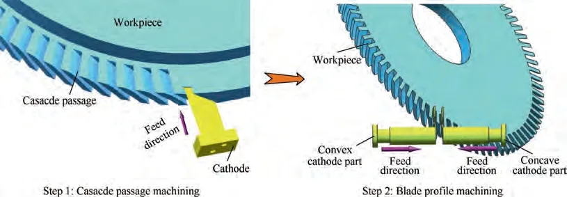
Fig. 1 Steps of blade profiles electrochemical machining.16
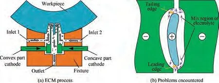
Fig. 2 Schematic diagram of blade profiles of blisk during electrochemical machining (ECM) under W-shaped flow mode.
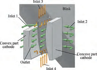
Fig. 3 Four-way flow mode.
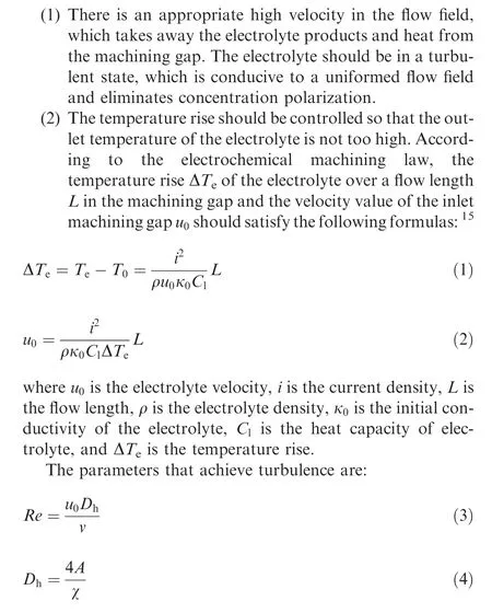
where Re is Reynolds number, ν is the kinematic viscosity. Dis the hydraulic diameter, A is the area of the overflowing cross-section, and χ is the perimeter of the contact boundary between the solid and the fluid at the cross-section.
In the ECM process,the electrolyte is sealed in a fixed processing fixture and stays in a turbulent state. The distribution of the flow field in the electrolytic machining fixture is complicated as the flow lines of the electrolyte in the machining gap are bent. Therefore, the RNG k-ε modelwas selected as the turbulence model for liquid flow.The corresponding transport equations are as follows:
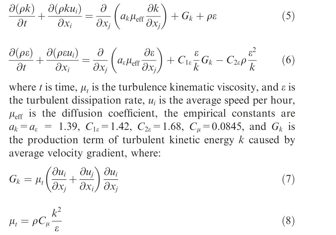
3.2. Results of numerical simulation
Owing to the complexity of the flow mode, a simplified model was used to analyze the flow field.When the process was in the final state,the uniformity of the flow field was the main factor affecting the machining quality of the profile. The simplified flow channel model of the W-shaped flow mode and the four-way flow mode was based on the cathode, workpiece,and fixture (Fig. 4). During the simulation of the flow modes,the boundary of the electrolyte inlet and outlet was defined by pressure type. The simulation of the mathematical model was obtained by the fluid analysis software.The pressures of inlet 1 and inlet 2 were 1.0 MPa, the pressures of inlet 3 and inlet 4 were 0.6 MPa, and the outlet pressure was 0.1 MPa. To analyze the distribution of the flow field parameters of the leading and tailing edges along the path flow,three cross-sections were chosen at 3 mm,9 mm,and 15 mm from the blade root as sections of the blade root (A), the blade body (B) and the blade(C) tip, respectively. The finite element method discretization meshes was demonstrated in Fig. 5.
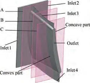
Fig. 4 Simplified flow field model.
After the numerical simulation, the velocity distribution of the electrolyte on the leading and tailing edges of cross-sections A, B, and C was obtained under two flow modes (Fig. 6). In the W-shaped flow mode, the velocity was not uniformed along the flow path, particularly on the tailing edge (Fig. 6(a)). The electrolyte flowed through the concave and the convex parts of the channel, then met at the leading and tailing edges, and an eddy was formed, which resulted in mechanical energy loss and reduction in the velocity. There was a lowvelocity region at A and B in the flow channel, which was caused by the collision of electrolytes at the convex and concave parts of the blade when the electrolyte entered the flow channel of the machining region.As product and heat removal is difficult, the cathodes and workpieces are easily damaged.The velocity at C increased,and a local,high-speed liquid flow area appeared near the leading and trailing edges.In the fourway flow mode(Fig.6(b)),the velocity was relatively high and the velocity distribution was more uniformed than the Wshaped flow mode along the flow path. The mixing regions of the electrolyte at the leading and tailing edges in this flow mode are eliminated. The turbulent area is moved to the profile. The four-way flow mode optimizes electrolyte flow throughout the processing,which is instrumental in improving the uniformity and stability of the flow field.
3.3. Flow field optimization
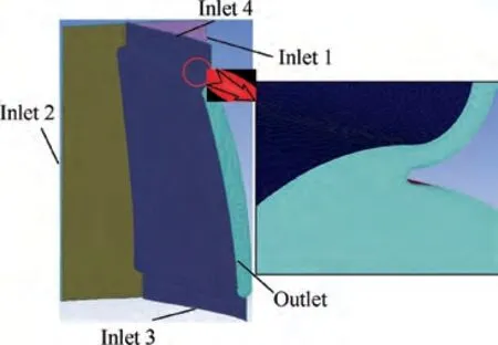
Fig. 5 Finite element method (FEM) discretization meshes.
Compared with the W-shaped flow mode, the four-way flow mode has many advantages, one of which is that inlet 3 and inlet 4 supply to the leading- and tailing-edge flow channels,respectively.The pressure of the electrolyte inlet on the leading and trailing edges affects the distribution of the flow field in the entire flow channel. To improve the uniformity of the leading and tailing edges,the pressure of inlet 3 and inlet 4 needs to be optimized.
When the process is in the equilibrium state, the pressures of inlet 1 and inlet 2 are set to 1.0 MPa and the outlet pressure is 0.15 MPa.Studies under different inlet pressures at the leading and tailing edges were performed. Several inlet pressures were chosen:0.2 MPa,0.4 MPa,0.6 MPa,and 0.8 MPa.After simulation calculation,the vector graphs and cloud map of the velocity in the tailing edge machining gap for the different conditions were acquired as shown in Fig. 7.
The conclusions drawn from Fig. 7 are as follows: When the pressure of inlet 3 and inlet 4 was 0.2 MPa (Fig. 7(a)),the distribution of velocity was non-uniformed,and the velocity at the tailing edge along the flow path was low. When the pressure of inlet 3 and inlet 4 was 0.4 MPa(Fig.7(b)),the distribution of velocity gradually became uniformed along the flow path. However, there was a large lack of liquid at B.When the pressure of inlet 3 and inlet 4 was 0.6 MPa (Fig. 7(c)), the mixed regions of the electrolyte and the areas of low liquid disappeared. The flow in different directions was uniformed with less mutual interference and a higher flow velocity along the flow path. When the pressure of inlet 3 and inlet 4 was 0.8 MPa(Fig.7(d)),the velocity decreased,however;there was a low-velocity region at B. When the pressure of inlet 3 and inlet 4 was similar to inlet 1 and inlet 2, a mechanical energy loss was caused by the liquid impact and compared with 0.6 MPa,the average flow velocity of each section was relatively low.As the pressure of inlet 3 and inlet 4 was changed,the area of the low-speed area reduced, and the uniformity of the flow field improved. When the value of the pressure reached 0.6 MPa, the flow field was more uniformed.
According to Eq. (2), the critical velocity in the flow channel under the turbulent state of the processing area is 4.68 m s. To analyze the uniformity of the flow field accurately at the leading and tailing edges under different pressures, the three cross-sections and five reference lines of the tailing edge were analyzed. As shown in Fig. 8, 1000 data points were taken on each cross-section, five reference lines were equally taken on a half-circle of 0.35 mm from the center of the arc at the tailing edge, and 200 data points were taken on each reference line.We assumed that ube the average velocity in a simulation,σbe the variance of the flow velocity about the 1000 data points, and pp be the percentage of the lowvelocity points whose velocities are below 4.68 m s.
To ensure that there is no shortage of liquid in the processing area and that the blade profile of the blisk in the ECM process can be performed steadily, the velocity must exceed a critical value. As shown in Table 1 and Fig. 9, the percentage of the low-velocity points was rather high when the pressure values were 0.2 MPa and 0.8 MPa. Combined with section A of Fig. 7(a)-7(d), short-circuiting during machining was more likely to occur at the root of blade.By contrast,when the pressure value was 0.6 MPa, the percentage of the low-velocity points was the lowest, which effectively reduced the short circuit owing to insufficient liquid.The average velocity under the four pressures was relatively high, and the largest variance occurred at 0.2 MPa, which indicates that the fluctuation of the velocity was large and leads to the instability of the flow field.However,when the pressure value was 0.8 MPa,the variance was at its smallest, which indicated that the fluctuation range of the velocity was small, but the percentage of the low-velocity points was rather high. Ultimately, the optimal pressure value was 0.6 MPa.
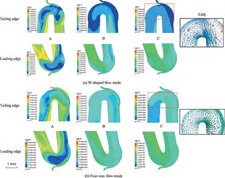
Fig. 6 Velocity distribution of blade leading and tailing edges under two flow modes along flow path.
To verify the validity of the above analysis, the 1000 data points on the five reference lines of the tailing edge were analyzed,and the percentage of low-velocity points,variance,and average velocity were used as evaluation indicators.The simulation results were given in Table 2 and Fig. 10. With the change of the pressure in inlet 3 and inlet 4, the lack of liquid at the leading and tailing edges in the processing area was eliminated.Although the electrolyte had an area with low-velocity,the number of low velocity points was greatly reduced,and the average velocity was greatly improved. The pressure of inlet 3 and inlet 4 increased from 0.2 MPa to 0.8 MPa and the percentage of low-velocity points was reduced. Although the percentage of low-velocity points of 0.8 MPa was 0.5%, the average velocity was higher than the other three pressure values, and the variance was large, which led to a large degree of dispersion.A comprehensive comparison showed that when the pressure of inlet 3 and inlet 4 was 0.6 MPa,the percentage of the low-velocity points was 0.1%, the stability of the flow field was higher, and the average velocity was up to 16 m·s.Thus, the above analysis was effective.
4. Experimental studies
To verify the feasibility of the four-way flow mode,a comparative experiment was performed on a dedicated ECM tool.The experimental processing conditions are shown in Table 3. The ECM fixture was designed and manufactured according to the four-way flow mode (Fig. 11(a)).
The processing experiments with the cathode feed rates of 0.5, 0.7, 0.8, 0.9, 1.0, 1.1 mm·min, and 1.2 mm·minwere performed, respectively. As shown in Fig. 12, under the Wshaped flow mode, when the feed rate was lower than 0.8 mm·min,the feed rate was stable and the processing current was low. However, when the feed rate was increased to 0.9 mm·min, the cathode had a severe short circuit, which indicates that the max feed rate of the W-shaped flow mode was 0.8 mm·min.At the same time,under the four-way flow mode, the processing process was more stable when the feed rate was 0.5-1.2 mm·min, and processing efficiency was improved. The current increased at the beginning of the processing,but once the current wave was constant,the processing tended to stabilize. Fig. 13 shows the current change during processing. Compared with the W-shaped flow mode, the four-way flow mode achieved equilibrium quicker. With the increase in feed rate, the balance gap between the cathode and the workpiece decreased,the machining current increased,and the material removal rate in the machining gap increased.The electrolytic products of the leading and tailing edges flow field could be removed and the risk of a short circuit was reduced.The experimental results showed that with a feed rate of 1.2 mm·minfor processing, the flow field was evenly distributed,and the processing efficiency was improved.Thus,the efficiency of the four-way flow mode was verified.
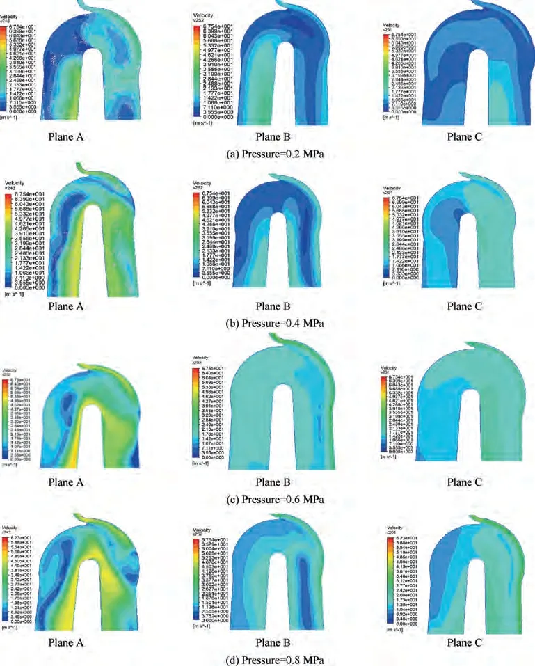
Fig. 7 Cloud maps of velocity distribution along flow path in tailing edge under different pressures of inlet 3 and inlet 4.
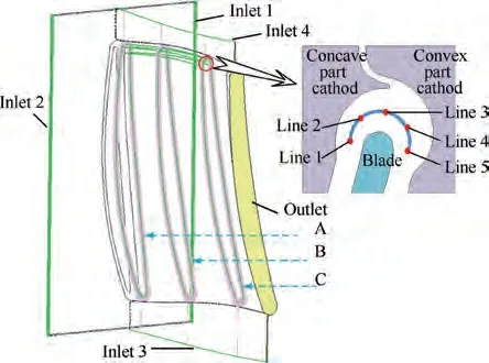
Fig. 8 Positions of sampling points.

Table 1 Velocity analysis of flow path under different pressures of inlet 3 and inlet 4.
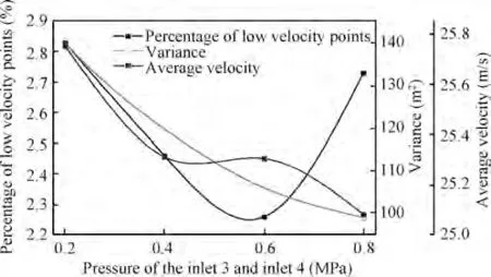
Fig. 9 Analysis of velocity in flow path at different pressures of inlet 3 and inlet 4.

Table 2 Analysis of velocity in flow field at different pressures of inlet 3 and inlet 4 in the five reference lines.
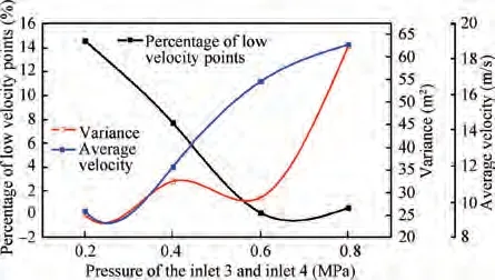
Fig.10 Changes in flow-field velocity with different pressures at inlet 3 and inlet 4 in the five reference lines.
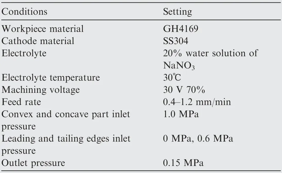
Table 3 Experimental conditions in electrochemical machining.
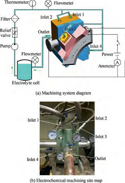
Fig. 11 Experimental set-up.
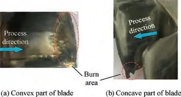
Fig. 12 Workpiece burns in W-shaped flow mode.
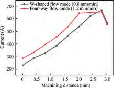
Fig.13 Changes in current during electrochemical machining of blade.
A sample machined by the two flow modes is shown in Fig. 14. On cutting the blades, cross-sections of the trailing edge contours along the flow path were observed,and the sections of blade root(A),blade body(B),and blade tip(C)were divided into two rows from top to bottom (Fig. 15). The Wshaped flow mode is shown in Fig. 15(a). The phenomenon of unilateral trimming appeared at the cross-section of A, B,and C, and the allowance on both sides was uneven along the flow path. The new flow mode proposed here is shown in Fig. 15(b). There are smoother arcs and less change in shape along the flow path.Compared with the W-shaped flow mode,the flow mode proposed here provides benefits during trailing edge formation.The electrolyte in the machining gap using the flow mode proposed here has a strong flushing ability, which means the dissolution of the workpiece was even.
The surface roughness of the convex and concave parts of the blade was measured by a profilometer (T800 SC,HOMMEL-ETAMIC, Germany) as shown in Fig. 16. The surface roughness of the convex part and concave part were
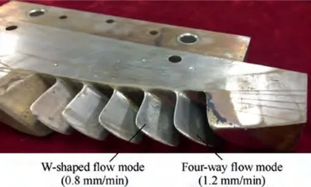
Fig. 14 Sample of blade profile of a blisk machined using two flow modes.
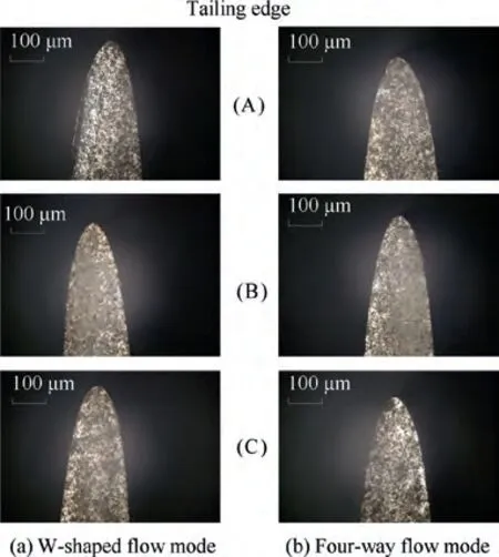
Fig.15 Contours of the trailing edges along flow path under two flow mode.
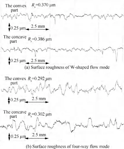
Fig. 16 Blade surface roughness.
R0.370 um and R0.386 um under the W-shaped flow mode.On the contrary,the surface of the blade processed by the fourway flow mode was smooth and the surface roughness of the convex part and concave part were R0.292 um and R0.302 um.The convex part was reduced by 21%,and the concave part was reduced by 21.7%. The results showed that the workpiece had good surface quality when the four-way flow mode was used.
5. Conclusions
(1) A four-way flow mode was proposed to eliminate mixed regions of electrolyte at the leading and tailing edges processing area, and the flow field uniformity was improved.
(2) A four-way flow mode was established,the full-profile of the flow field simulation analysis was performed. The optimal pressure parameters of the leading and tailing edges were obtained. The optimal pressure was 0.6 MPa. The results showed that the velocity of the electrolyte increased significantly, and the uniformity of the flow field was improved.
(3) A comparative experiment was performed between the W-shaped flow mode and the four-way flow mode, the results showed that the electrolyte flow was more uniform and the machining stability and surface quality of the four-way flow mode were higher than those of the W-shaped flow mode.
The authors declare that they have no known competing financial interests or personal relationships that could have appeared to influence the work reported in this paper.
This study was co-supported by the National Nature Science Foundation of China (No. 91860135), National Natural Science Foundation of China for Creative Research Groups(No.51921003),National Science and Technology Major Project (No. 2017-VII-0004-0097).
