Ground-based investigations on phase-moving phenomenon with space sublimation cooling for lunar exploration missions
Enhui LI, Yunze LI,*, Jixing WANG, Mn YUAN, Jingyn XIE,Yuehng SUN, Lizhu YANG, Xinwen NING
a School of Aeronautic Science and Engineering, Beihang University, Beijing 100083, China
b Beijing Key Laboratory of Space Thermal Control Technology, China Academy of Space Technology, Beijing 100094, China
KEYWORDS Lunar vacuum environment;Phase-change flow;Space sublimation cooling;Unsteady phase-moving phenomenon;Visualized ground-based experimental approaches
Abstract The lunar surface is a typical vacuum environment, and its harsh heat rejection conditions bring great challenges to the thermal control technology of the exploration mission. In addition to the radiator, the sublimator is recommended as one of the promising options for heat rejection.The sublimator makes use of water to freeze and sublimate in a porous medium,rejecting heat to the vacuum environment.The complex heat and mass transfer process involves many physical phenomena such as the freezing and sublimation phase change of water in the porous medium and the movement of the phase-change interface.In this paper,the visualized ground-based experimental approaches of space sublimation cooling were presented to reveal the moving law of threephase point and the growth phenomenon of ice-peak and icicle in microchannels under vacuum conditions.The visualized experiments and results prove that the freezing ice is divided into the porous ice-peak and the transparent icicle. As the sublimation progresses, the phase-change interface moves downward steadily, the length of the ice-peak increases, but the icicle decreases. The visualized experiments of space sublimation cooling in the capillary have guiding significance to reveal the sublimation cooling mechanism of water in the sublimator for lunar exploration missions.
1. Introduction
Since the 1960s, the success of USA Apollo missions has marked the beginning of lunar exploration. With the rapid development of space exploration missions,such as the lunar space station, manned lunar missions, and planetary habitation programs, the increasing heat rejection requirements and extreme space environment have brought great challenges to the Thermal Control System(TCS)of spacecraft.For example, space activities on the lunar surface usually take place in the noon when sufficient solar energy supply is available.However, the lunar surface’s temperature at that time approaches above 120 °C, which will bring a big problem for the TCS using radiation to reject the generated heat to outer space.What’s worse, the dust on the lunar surface severely affects the radiator’s cooling ability, which will overwhelmingly deteriorate the already-bad thermal control situation.To solve these thermal control problems,the expendable heat sink,sublimator, with its simple structure and no moving parts, has been successfully used in the thermal control design of early Apollo missions and spacesuits.
Recently, the United States announced that the Artemis manned lunar mission is expected to return to the moon by 2024.At the same time, China’s lunar exploration program and many other countries have shown the renewed interest in lunar exploration.The thermal control system closely associated with the lunar exploration mission is crucial. To improve the cooling performance of the thermal control system,a sublimator is still recommended as one of the promising options,as shown in Fig. 1.Sublimators, which use water sublimation heat (2835 kJ/kg) to transport the heat to outer space,are proved to be an available expendable heat sink that can be particularly operated in the space vacuum environment.
Investigations on the sublimator can be traced back to the 1970s when researchers in the USA Hamilton Standard Corporation adopted a one-dimensional heat conduction model to study the periodical operating mode of the sublimator.In recent years, NASA has proposed a variety of new conceptual designs of water sublimators and conducted corresponding prototype tests. Leimkuehler et al.proposed the Contaminant Insensitive Sublimator (CIS) in view of the shortcomings of the traditional sublimator that are sensitive to non-volatile contamination in feed water and tested its heat rejection performance. Sheth et al.proposed the Sublimator Driven Coldplate (SDC) that eliminates the pumped fluid loop,potentially increasing reliability and reducing complexity while saving both mass and power. Based on the SDC, Leimkuehler and Kennedyproposed an Integrated Sublimator Driven Coldplate (ISDC) by integrating the cold plate and the sublimator to improve heat rejection performance. It is worth noting that previous investigations on water sublimator mainly focused on the experimental test,which can be divided into: (A) integral performance test of traditional and new water sublimatorsand (B) system-level performance test of the thermal control system including the water sublimator.Additionally, numerical researches mainly include:(A)mathematical modeling of heat and mass transfer in water sublimatorand (B)the CFD simulation of water sublimator.However, these researches are all based on a large number of assumptions and cannot accurately reveal the complex physical process in the sublimation phenomenon. Furthermore, few visual experimental tests have been conducted on sublimation behavior and phase-change interface motion in porous media under the vacuum condition. To understand the heat and mass transfer mechanism of phase-change flow and phase-change interface motion in microchannels, it is of great significance to perform a ground-based visualization experiment.
From the literature review, it can be concluded that up-todate investigations on the sublimator primarily focus on its macro thermal performance while ignoring its microscale phase-changing flow inside the porous material, thus leading to a lack of knowledge in the internal fluid flow and phasechange phenomenon,especially in the porous area.In the field of experimental study, it is believed that visualized methods can fill such knowledge gap. It is particularly difficult to observe the phase-change phenomenon as the porous plate is made of non-transparent metal materials and the thickness of the plate itself is very thin (~1 mm). In the theoretical study, most publications are devoted to the steady-state numerical analysis of the sublimation while fail to disclose the unsteady moving phase-change process. Also, theoretical papers are all based on a large number of assumptions, and thus cannot accurately reveal the complex physical process inside the sublimator porous material. In conclusion, current investigations concerning sublimators fail to uncover the internal interfacial behavior, which causes an incomplete grasp of the operating mechanism of the sublimator. Such deficiency leads to several problems in the deployment of sublimator in spacecraft: (A) the heat dissipation rate of the sublimator is not competent, only 100 W/cm, even lower than the singlephase cooling devices; (B) the operation of the sublimator is not always reliable, where operation failure would take place from time to time.

Fig. 1 Thermal control system of water sublimator for lunar exploration missions.11,12.
It is imperative to propose a visualized technology especially for the observation of the internal moving phasechange process. Observational techniques, such as the microscale infrared/visible observation technique,the photolithography technique, high-speed video imaging systems, and the Xray microtomography, have been adopted to analyze the phase-change behavior in porous structures.Also, observation of two-phase flowis always in the spotlight while ignoring the three-phase flow where liquid, gas, solid phases co-exist. Therefore, such technology can barely be used to observe the phase-change process within a 1 mm thick nontransparent plate where both image resolution and magnification are strictly required.What’s worse,the sublimation experiment is needed to be operated in a vacuum environment for a ground-based study,which increases the difficulty of the observation.Considering the rationality of the assumption that capillary pipes are equivalent to porous materials in previous theoretical analysis, the sublimation behavior in glass-made transparent capillary pipes under vacuum conditions is adopted as the focus in this paper.Besides,the similarity principle is adopted to extend the microscale porous area to macroscale one, which can magnify the involved phasechange process and facilitate a clear observation of the phase-change sublimation process.
In this paper,visualized experiments have been presented to reveal the moving law of three-phase point and the growth phenomenon of ice-peak and icicle.The experimental methods were performed to conveniently track the gas-solid-liquid interfaces, and their dynamic movement under different water supply temperatures and pressure. Meanwhile, frozen zone stratifying, bubble dynamics, and ice breakthrough phenomenon are analyzed visually and quantitatively as well.This paper is devoted to an effective ground-based observation method to understand the mechanism of sublimation cooling and ice breakthrough in micropores.
2. Sublimation cooling phenomena and ground experimental methods
2.1. Phase-moving phenomenon with space sublimation cooling
A detailed structure of a traditional sublimator (based on the water sublimator in X-38/ Crew Return Vehicle) is mainly composed of a feedwater chamber and a porous plate with general pores of 3 ~100 μm. Exposed to the space vacuum environment, the feed water pressure in the porous plate will experience a sharp decrease from the inlet pressure to the three-phase point (610.62 Pa and 273.15 K) where the liquid water will be solidified into ice quickly.The dense porous plate exerts great resistance to phase-change flow which assists to fix the ice layer.At this point,the direct sublimation process from ice to vapor without melting occurs when waste heat is charged into the sublimator system. Adopting this mechanism, a liquid-solid-vapor phase change takes place to maintain the temperature of the device and crews.
The sublimation cooling and phase-change process of water in a single micropore is depicted in Fig. 2. When liquid water direct contact with the vacuum environment in the capillary,the liquid water evaporates water vapor into the vacuum environment, as shown in Fig. 2(a). The water in the capillary starts to freeze and sublimates water vapor into the vacuum,where the ice blocks the liquid water flow, as shown in Fig. 2(b). With the sublimation process, the ice in the porous plate gradually thins,as shown in Fig.2(c).When the adhesion of the ice reaches its limit, the sublimator suffers from an icebreakthrough failure where ice layer is punctured by liquid water (‘‘ice breakthrough”), as shown in Fig. 2(d). In the‘‘breakthrough” mode, the liquid-phase feed water travels directly through the porous plate, which causes a coolant waste. Liquid water exposed to vacuum refreezes and sublimates,repeating in the order Fig.2(b)to Fig.2(e)periodically.
2.2. Design of capillary visualization apparatus and ground experimental system
The objective of the present ground-based experiment is to investigate the interface movement caused by the sublimation phase change of water in the porous plate under vacuum conditions, and thus to explore the mechanism of water sublimation in the sublimator. In the theoretical modeling of water sublimators, one of the reasonable and widely used assumptions is that the porous material is equivalent to a flat microporous channel.This idea of equivalence provides a prototype reference for the visualized ground-based experimental approaches in this paper. It should be noted that the pore size of the porous plate in the water sublimator is generally tens of microns.If equivalence strictly follows the approximate aperture, no matter using capillary or glass bead, it will bring a great challenge to the sample manufacturing. To sum up, the movement of the sublimation phase-change interface and the growth of different ice forms can be observed by ground-based experiments with capillary equivalent porous media, as shown in Fig. 3(a), which will make us understand the basic flow and heat transfer law inside EVA spacesuit sublimation cooler in lunar vacuum environment.

Fig. 2 Sublimation cooling and phase-change process of water in single micropore.
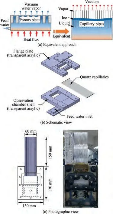
Fig. 3 Design of capillary visualization apparatus.
In this paper, the visualization apparatus is a key component,and its structure is presented in Fig.3(b)and 3(c).It consists of quartz capillaries and a water storage chamber. There were 30 capillary tubes with diameter of 1 mm and length of 20 cm. The quartz capillaries were inserted into the acrylic structure plate and the joint was sealed with vacuum glue.Liquid water can be successively through the water supply copper pipe,into the water storage chamber,and finally,flow through the capillary contact vacuum environment. The internal flow and solidification-sublimation interface movement could be observed in the transparent quartz capillaries. Besides,a more accurate film ruler is used next to the capillaries to obtain the position data in each capillary, as can be seen from Fig. 3(c).
Fig.4 provides the schematic view of the visual experimental system.The system consists of a vacuum subsystem,a water supply subsystem, a data measurement/acquisition subsystem,and a capillaries visualization apparatus. The photographic view details of the visual experimental system are shown in Fig. 5.
The vacuum subsystem consists of a vacuum chamber,vacuum pipelines, a vacuum pump, and two vacuum regulating valves. The vacuum chamber adopted a borosilicate glass bell jar with a diameter of 0.5 m and a height of 0.5 m to provide vacuum conditions for the sublimation of water. The vacuum pipelines used alloy bellows of different diameters. The vacuum pump is a PRONTEK 2RH030C double-stage rotary vane pump.The vacuum regulating Valves I and II can adjust the pressure of the vacuum chamber and water tank respectively by changing the flow resistance of their series pipelines.Furthermore, considering that a large amount of water vapor generated by reducing the pressure of the water tank may damage the vacuum pump, a gas-liquid separator and a filter are added as shown in Fig. 5(a).
The water supply subsystem utilized the pressure difference between the water tank and the vacuum chamber to drive distilled water from the water tank through the red copper tube with an inner diameter of 2 mm to the visual porous pipe apparatus. Therefore, the water supply flow can be coarsely regulated by changing the tank pressure, and then finely regulated by the height adjuster and water-supply line’s control valve.
The data measurement/acquisition subsystem mainly completed the measurement of pressure,temperature,and flow rate of the experimental system and the acquisition of visual data.The vacuum pressure of the vacuum chamber and water tank is measured by ZDZ-52 T resistance vacuum gauges. The water temperature and pressure in the water supply line are measured by Pt100 thermal resistance and pressure transmitter respectively. The micro liquid flowmeter is used to measure water supply flow. The above temperature, pressure, and flow rate are measured with appropriate range and uploaded to Agilent 34972A data acquisition instrument for processing.The position of the visual phase-change interface at different moments was recorded by the HD digital camera.
2.3. Experimental procedure and testing conditions
The experimental procedure is described as follows: (A) The preparation before the experiment mainly includes closing the water supply Valves I and II, closing the exhaust valve of the vacuum chamber, and opening the Vacuum valves I and II. (B) Open the vacuum pump and adjust the Vacuum valve II to adjust the pressure of the water tank. The pressure of the vacuum chamber is adjusted by changing the flow resistance of the vacuum pipeline. When the open of Valve II is changed, the pressure in the vacuum chamber will fluctuate and needs to be stabilized for some time. (C) When the pressure of the water tank and the vacuum chamber is stable,slowly open the water supply Valves II and I in turn and start the water supply. (D) When water enters capillaries, it is first sprayed directly into the vacuum chamber and rapidly frozen at the capillaries’ outlet. Open the digital acquisition instrument to record data. When ice is stable in capillaries, the flow rate also changes steadily. When the phase change is stable in capillaries, the camera is turned on for visualized recording.(E) Photographs were taken at intervals of 5 min until ice breakthrough occurred in a large number of capillaries. (F)Turn off the water supply and the vacuum pump. (G) Change the condition and start a new experiment.
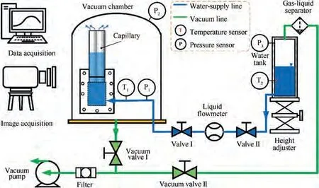
Fig. 4 Schematic view of visual experimental system.
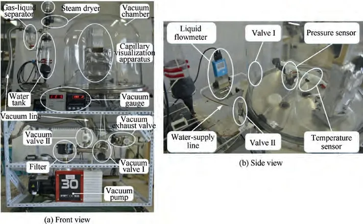
Fig. 5 Photographic view of visual experimental system.

Table 1 Testing conditions.
The setting conditions are shown in the Table 1.The effects of different water flow rates and pressure on sublimation behavior in capillaries were studied by maintaining constant pressure in the vacuum chamber. The experimental results show that when the water supply pressure is low,the capillaries will randomly spray ice one by one.When the pressure is high,most of the capillaries will spray ice at the same time.According to the difference of ice breakthrough, the water supply pressure is divided into low-pressure and high-pressure ranges.
Due to the large difference between the water supply pressure and sublimation pressure, the actual process is that the water will be quickly ejected and frozen at the capillaries’outlet.As the sublimation progresses,the ice near the outlet of the capillary gradually moves down.At the beginning of the experiment, a large amount of ice breakthrough and bubbles in the capillaries will be generated. We chose to start recording the time and taking visual pictures when the imaging effect was good. For all data to have the same starting point, we will freeze at the outlet of the capillary as the initial state.The data of all working conditions are re-fitted and shifted to have the same time starting point.
3. Experimental results and discussion
3.1. Visualization of sublimation freezing zone
Under certain conditions of water supply pressure, temperature, and flow, the water in the capillaries freezes and forms an ice plug on the side near the vacuum. Typical ice is made up of two parts (ice peak and icicle) as displayed in Fig. 6(a). On one side of the vacuum is opaque, porous ice, known as the ‘‘ice peak” for its conical shape. The ice peak consists of fine-grained ice and continuously sublimate water vapor into the vacuum.The other,between an ice peak and the liquid water,is a vitreous cylindrical zone called the‘‘icicle”.The icicle is a transparent nonporous layer that sticks firmly to the porous pipe wall, preventing liquid water from entering the vacuum directly. It is noteworthy that two menisci can be found on the upper and lower sides of the icicle.Alternatively,in some capillaries, we find a vapor zone between the ice peak and the icicle, and bubbles of vapor in some icicle layers, as depicted in Fig. 6(a) and 6(b).
When the liquid water in the capillaries is exposed to the vacuum environment, the liquid water near the vacuum side will freeze quickly and form a certain amount of supercooling(less than the corresponding temperature of the three-phase point) because the vacuum pressure is far lower than the three-phase point pressure. The heat transfer between liquid water and ice in the capillaries depends on heat conduction,and the temperature gradient changes mainly along the axial direction of the capillaries. Therefore, the temperature change between the liquid water (>0 °C) and the subcooled ice(<0 °C) is bound to exist in a region less than 0 °C, which is the sublimation frozen zone. Freezing occurs when the temperature of liquid water in capillaries is below or equal to 0°C.
The capillary wall is not adiabatic and there is a certain amount of heat input, resulting in a growing crystal that is a cone.The rapid decrease of temperature caused by sublimation will lead to certain thermal stress. The formation of porous‘‘ice peaks” is related to the large plastic deformation caused by thermal stress.Alternatively, macroscopic ice is a polycrystalline form.X-ray diffraction indicates that ice belongs to the hexagonal crystal system.The grain boundaries between grains of different orientations and the interfaces between impurities and bubbles in ice crystals scatter some of the incident light more or less.This explains why the porous ice peaks are white.Conversely,icicles grow as cooling and solidification gradually‘‘creep”toward the water supply side.When the cooling rate is slow,the bubbles and impurities in the water have enough time to diffuse to the surface and spillover.And the low cooling rate also helps to form larger grains and reduce the number of grain boundaries, so the icicles are more transparent. The circle in Fig. 6(a) illustrates bubbles appearing in the icicle, which is related to the heat input from the capillary wall. The bubbles move to the sublimation surface where the pressure is lower and stop at the interface between porous ice peak and icicle,which may explain the existence of a void between a frozen icicle and porous ice peak. As shown in Fig. 6(b), the closer the bubbles are to the sublimation interface,the larger the bubbles are, which is mainly related to the lower pressure at the sublimation interface.
3.2. Effects of sublimation on ice peaks and icicles
The typical process of the movement for the phase-change interface in the capillary is shown in Fig.7.In the initial stage of water freezing and sublimation,the ice layer blocks the fluid flow. The ice layer near the water supply side and the vacuum side correspond to the solidification interface and the sublimation interface respectively. As the sublimation continued, it was found that the phase-change interface gradually moved down, as shown in the Fig. 7(a)-7(d). When the sublimation in the capillary reaches a certain stage, the phenomenon of‘‘ice breakthrough” will occur in the capillary, as shown in Fig.7(e).At this time,the liquid water is sprayed into the vacuum environment outside the capillary,and instantaneously,it freezes at the exit of the capillary and forms an ice layer again to block the flow in the capillary. After that, the ice layer is formed again and the phase-change interface slowly moves down, as shown in Fig. 7(f) and 7(g). As the sublimation continues, the ice breakthrough reappears on individual capillaries, as shown in Fig. 7(h).
Under different working conditions, the variation of ice peak and icicle length with sublimation time can be compared in Fig.8 and Fig.9.It is generally found that the length of the ice peak increases with the sublimation cooling process,and on the contrary, the length of the icicle decreases with the sublimation cooling process. Particularly, as presented in Fig. 6(c), the ice peaks grow, break, and fly away over time. The break and fly-away of the ice peak make the length of the ice peak decrease, which well explains the trend of the ice peak slowing down or even falling with the change of time.Besides,there is a critical value for the transparent icicle layer. When the length of the icicle reaches this value, the adhesion of the icicle decreases and it finally breaks through.Ice breakthrough is mainly divided into two situations, namely, the capillaries will spray ice one by one successively, as depicted in Fig. 10 and Fig. 8, and the ice breakthrough in multiple capillaries occurs at one time, as shown in Fig. 9 and Fig. 7(e) and 7(h).

Fig. 6 Photographic view of sublimation freezing zone.
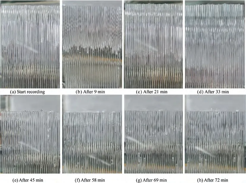
Fig. 7 Typical process of the movement for phase-change interface ((a)-(d) Pphase-change interface gradually moves down; (e) Ice breakthrough appears one after another in the capillaries; (f) Refreeze; (g) Move down again; (h) Reappearance of ice breakthrough on individual capillaries).
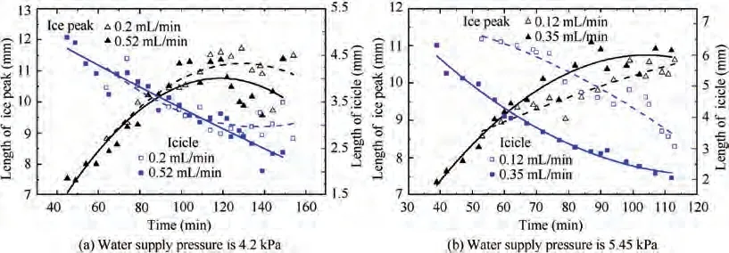
Fig. 8 Low-pressure interval (Successive ice breakthrough, water supply temperature is 19.9 °C).
3.3. Movement of phase-change interface
In this paper, the interface between the ice peak and the icicle is selected as the sublimation interface. It can be found that with the increase of sublimation time,the sublimation interface keeps moving down until the phenomenon of ice breakthrough occurs. The water supply pressure of 4.2 kPa and the water supply flow of 0.52 mL/min are taken as an example. Fig. 10 provides the movement of the sublimation interface in the capillaries. The yellow line is the average position of the sublimation interface in 30 capillaries. It can be seen from Fig. 10(e)and 10(f) that individual capillaries spray ice and then refreeze.
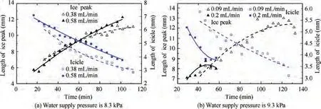
Fig. 9 High-pressure interval (Disposable ice breakthrough, water supply temperature is 19.7 °C).
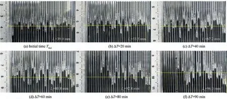
Fig. 10 Movement of phase-change interface in capillaries (4.2 kPa, 0.52 mL/min).
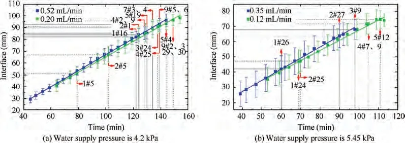
Fig. 11 Low-pressure interval (Successive ice breakthrough, water supply temperature is 19.9 °C).
The movement of the sublimation phase-change interface under different working conditions is illustrated in the figure below. As shown in Fig. 11, when the water supply pressure is low(4.2 kPa and 5.45 kPa),the ice in the capillaries is ejected one by one. As the water supply pressure increases, the ice breakthrough occurs faster. However, in Fig. 12, when the water supply pressure is high (8.3 kPa and 9.3 kPa), a large amount of ice in the capillaries will be ejected at the same time.Under the same water supply pressure, the greater the water supply flow is, the faster the ice breakthrough occurs.
3.4. Ice breakthrough phenomenon
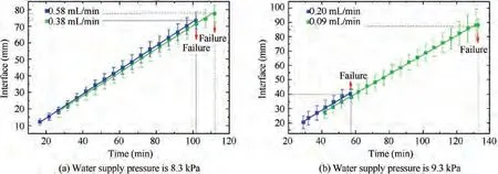
Fig. 12 High-pressure interval (One-time ice breakthrough, water supply temperature is 19.7 °C).
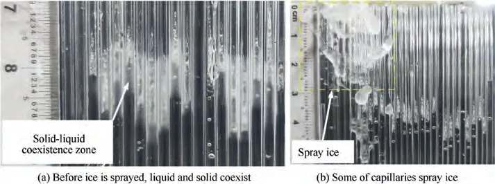
Fig. 13 Ice breakthrough.
With the sublimation of ice, the ice plug is not firmly adhered to the capillaries’ wall. Finally, the pressure difference ejects the ice from the capillaries,and the liquid water passes through the capillaries directly to the vacuum.Under certain conditions of flow and water supply pressure, on the one hand, the pressure on the water supply side increases due to ice blockage,and on the other hand, the thickness of the icicles gradually decreases as the sublimation progresses. When the adhesion limit of the icicles to the capillaries’ wall is reached, the ice breakthrough will occur. At this time, the pressure on the water supply side is released,and the liquid water quickly cools and freezes in contact with the vacuum to re-establish balance,which changes periodically. But at the same time, ice breakthrough is also random.
As can be seen from Fig. 13, before the ice breakthrough occurs, the icicles begin to melt, creating a state of liquid ice coexistence. Ice blocks liquid water in capillaries. As the supply continues, the water supply pressure increases. Ice breakthrough occurs when the pressure increases to a certain limit.Meanwhile, the water supply pressure will be released. This will provide a possibility to use a periodic water supply strategy to solve the problem of ice-breakthrough failure inside the water sublimator.
4. Conclusions
In this paper, transparent straight capillaries are used as visualization methods to study the movement of water sublimation phase-change interface under vacuum conditions. Groundbased experiments on sublimation cooling are completed,and the movement of sublimation interface, the growth of ice-peak and icicle in capillaries, and the phenomenon of ice breakthrough are discussed in detail. The main conclusions of ground-based investigations are drawn as follows:
(1)In the capillaries,the freezing region caused by sublimation phase change consists of two main parts.Close to the vacuum is an opaque, porous ice region known as the ‘‘ice peak”for its conical shape, which consists of fine ice that sublimates continuously into the vacuum.Near the water supply,between the ice peak and the liquid water, is a glass cylindrical area called an icicle.
(2) It is generally found that the length of the ice peak increases with the sublimation cooling process,and on the contrary, the length of the icicle decreases with the sublimation cooling process. With the increase of sublimation time, the sublimation interface keeps moving down until the phenomenon of ice breakthrough occurs.
(3) Ice breakthrough is periodic. When the water supply pressure is low, the ice in the capillaries is ejected one by one, and when the pressure is high, a large amount of ice in the capillaries is ejected at the same time.
Exploring the sublimation behavior in the capillaries under vacuum conditions is of guiding significance for understanding the internal mechanism of the sublimator and improving the efficiency of the water sublimator for lunar exploration missions. Further work can be done to investigate the effects of water temperature, pressure, and flow on heat and mass transfer.
The authors declare that they have no known competing financial interests or personal relationships that could have appeared to influence the work reported in this paper.
This work was primarily funded by the cooperative project offered by Beijing Key Laboratory of Space Thermal Control Technology.It was also funded by China Postdoctoral Science Foundation (No. 2020 M671618).
