Improving performance of macro electrolyte jet machining of TC4 titanium alloy:Experimental and numerical studies
Minglu WANG, Ningsong QU
College of Mechanical and Electrical Engineering, Nanjing University of Aeronautics and Astronautics, Nanjing 210016, China
KEYWORDS Electrochemical machining;Macro electrolyte jet machining;Product removal;TC4 titanium alloy;Tool end structure
Abstract Electrolyte jet machining (EJM) is a promising method for shaping titanium alloys due to its lack of tool wear,thermal and residual stress,and cracks and burrs.Recently,macro-EJM has attracted increasing attention for its high efficiency in machining wide grooves or planes.However,macro-EJM generates large amounts of electrolytic products, thereby increasing the difficulty of rapid product removal with a standard tool and reducing the surface quality. Therefore, for enhanced product transport, a novel tool with a back inclined end face was proposed for macro-EJM of TC4 titanium alloy.For comparison,also proposed were ones with a standard flat end face,a front inclined end face,and both front and back inclined end faces.The flow field distributions of all proposed tools were simulated numerically,and experiments were also conducted to validate the simulation results.The results show that one with a 5°back inclined end face can decrease the lowvelocity flow zone in the machining area and increase the high-velocity flow zone at the back end of tool, thereby promoting rapid product removal. A relatively smooth bright-white groove surface was obtained.The same tool also resulted in the highest machining depth and material removal rate among the tested ones.In addition,rapid product removal was beneficial to the subsequent processing. Because of its rapid product removal, the machining depth and material removal rate during deep groove machining using the tool with a 5° back inclined end face were respectively 7% and 14%higher than those produced using a standard one.Moreover, the lowest bottom height difference of 0.027 mm can be obtained when the step-over value was 8.2 mm,and a plane with a depth of 0.285 mm and a bottom height difference of 0.03 mm was fabricated using the tool with a 5° back inclined end face.
1. Introduction
Titanium alloys are used extensively in the aerospace industry because of their excellent mechanical and physical properties,high corrosion resistance at elevated operating temperatures,and low density.However,they are classified as difficult-tocut materials because of their poor machinability.For difficultto-cut materials, traditional mechanical machining causes severe tool wear, resulting in high costs and long processing cycles.A common method for machining difficult-to-cut materials is electrical discharge machining,but that also inevitably causes tool wear and forms a recast layer on the machined surface, resulting in lower machining quality.
Compared to other machining methods, electrochemical machining (ECM) is a promising method for shaping difficult-to-cut materials because of its lack of tool wear, thermal and residual stress, and cracks and burrs.Electrolyte jet machining (EJM) is an important form of ECM. In EJM,electrolyte is ejected from a nozzle, and the material of workpiece is removed only in the area localized by the electrolyte jet. Compared to conventional sinking ECM, EJM is widely applicable for fabricating grooves, planes, and other complex structures because of its simple tool structure and high flexibility.In micro-EJM,Natsu et al.used a tube electrode with an inner diameter of 0.26 mm to machine high-quality grooves in SUS304 stainless steel.Hackert-Oschatzchen et al. produced a micro-reactor on a stainless-steel surface by using a nozzle with a 0.1-mm inner diameter.Mitchell-Smith et al.produced different groove geometries by optimizing the bottom structure of a cylindrical nozzle with a 1-mm internal diameter.Bisterov et al. succeeded in reproducing ‘‘The Starry Night” on stainless steel by using a nozzle with a 0.25-mm internal diameter.Zhao and Kunieda used a tube electrode with a 0.3 mm inner diameter to machine threedimensional freeform surfaces.During micro-EJM, using some auxiliary methods to promote product transfer can have a positive effect on the surface quality. For example, the surface quality can be improved by adopting high-frequency vibrations,ultrasonic assistance,and axial suction.Furthermore, Mitchell-Smith et al. changed the nozzle clamping form to increase the current density at the end of the electrode and improved the surface quality greatly by using the push mode,and Clare et al. used the push mode to generate complex features and succeeded in fabricating typical biomedical stent geometries.
Recently, increasing attention has been paid to macro-EJM.Macro-EJM mainly uses a larger size through-hole tube electrode as cathode,which is an important processing form in inner-jet electrochemical milling. In addition, a dead-end tube electrode is also usually used in inner-jet electrochemical milling, which can remove workpiece material by jetting electrolyte from the side wall of a rotating electrode.Although the dead-end tube electrode can acquire a larger machining depth in a single feed, the feed speed is seriously limited and the machining efficiency is relatively low. In contrast, macro-EJM has a lager parameter window of feed speed, thereby improving the machining efficiency. Compared to micro-EJM, macro-EJM has the advantage of highly efficient material removal, especially in machining wider grooves or planes.However, macro-EJM generates more electrolytic products,thereby increasing the difficulty of rapid product removal. If products are not removed rapidly, then they will accumulate in the machining area and increase stray corrosion; therefore,in macro-EJM,rapid product removal is vital for surface quality. In macro-EJM, Liu et al. used a standard tube electrode with a 2 mm inner diameter to machine grooves on titanium alloys under different processing parameters,and a black product layer was clearly visible on their machined surface,showing poor surface quality.This indicates that the standard tool structure cannot meet the requirements of rapid product removal during macro-EJM. To enhance product transport,Liu and Qu improved the flow distribution in the machining area by proposing different sloping structures at the end of the cathode tool; they found that an upward-sloping end removed products rapidly, and a high-quality groove with a bright-white surface was obtained.However, their proposed upward-sloping end structure reduced the effective working area at the bottom of the tool electrode, thereby decreasing the machining efficiency and limiting the application range of tool.
Herein, for enhanced product transport without reducing the effective working area at the tool end, a novel tool with a back inclined end face was proposed for macro-EJM of TC4 titanium alloy.For comparison,also proposed were tools with a standard flat end face, a front inclined end face, and both front and back inclined end faces.The flow field distributions of proposed tools with different end structures were simulated numerically, and experiments were performed to validate the simulation results. The surface qualities, crosssection profiles,and material removal rates(MRRs)of grooves machined by all the tools were analyzed in detail.The effects of product adsorption on subsequent processing during deep groove machining were also examined. In addition, the stepover during wider groove or plane machining was also investigated.
2. Tool design and numerical simulation
2.1. Tool design
To produce flat-bottom grooves, a rectangular end face and rectangular jet channel were used for the cathode tool. In macro-EJM, electrolytic products are generated in abundance in the machining area, and removing them rapidly is vital for surface quality.Changing the end structure of the cathode tool can improve the flow field distribution to promote product transport. Therefore, to reduce the flow resistance in the machining area for enhanced product transport, the novel tools with different end structures shown in Fig. 1 were proposed. As well as a standard tool (tool A), ones with a front inclined end face (tool B), a back inclined end face (tool C),and both front and back inclined end faces (tool D) were designed here, and the inclination angles of the ends of tools B-D were all 5°. Our proposed tools are aimed at exploring the effects of different end structures on product transport,and finding a suitable end structure to produce high-quality machined surfaces.
2.2. Numerical simulation
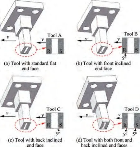
Fig. 1 Design of cathode tools with different end structures.
The strong self-passivation of titanium means that titanium alloys are relatively sensitive to the flow field distribution in the machining area. A proper flow field distribution can remove products quickly and improve surface quality, so the flow field distributions of the proposed tools with different end structures were analyzed using the computational fluid dynamics software Fluent 17.0. Fig. 2 shows the flow field analysis model and the related boundary settings. As can be seen in Fig.2,the related boundary conditions mainly included the inlet of electrolyte, outlet of electrolyte, wall of electrode and wall of workpiece.Because of the openness of the processing area, a mixed gas-liquid mode was adopted for the main body of the fluid domain. The element size of mesh was set to 0.08 mm and this was the same for all models.The standard k-ε turbulence model was used for the numerical simulation,it being a common model in ECM flow field analysis. Table 1 lists the parameters of the numerical modes. Also, to simplify the analysis model, the ECM flow field distribution was analyzed in a stable processing state under the following assumptions:(i)the electrolyte flow is incompressible,continuous,and conserves mass and momentum; (ii) the electrolyte temperature remains constant during ECM; (iii) all machining products generated during ECM are ignored.
Fig. 3 shows the air volume fraction and velocity distribution of electrolyte at section XZ for each model. As can be seen, with a standard tool (tool A), the high-velocity flow zones at the front (R) and back (S) ends were relatively small,which might inhibit rapid product removal and increase stray corrosion.Also,the machining area contained an obvious lowvelocity flow zone that makes rapid product removal more difficult.Products are more likely to accumulate in the machining area with using tool A.
When the tool had a front inclined end face (tool B), the high-velocity flow zone at front end R was larger than that with tool A,indicating that front inclined end face can enhance the product transport at the front end R of tool. However,compared to tool A, there was almost no increase in the high-velocity flow zone at the back end S of tool B, and tool B had an increase in low-velocity flow zone in the machining area. This might hinder rapid product removal at the back end S of tool and make it easier for products to accumulate in the machining area.
When the tool had a back inclined end face (tool C), the high-velocity flow zone at front end R was almost unchanged compared to tool A, but at back end S the high-velocity flow zone was much larger. Because the tool electrode should be fed forward continuously, the material of the workpiece surface must be eventually removed by the electric field provided by the back end of the tool. Mitchell-Smith et al. found that the processing at the back end of the tool electrode determined the final surface quality during EJM.Therefore, rapid product removal at back end S is vital for the final surface quality.The back inclined end face obviously increased the highvelocity flow zone at back end S, thereby enhancing product transport at the back end of the tool. This can reduce stray corrosion and improve surface quality. Also, the low-velocity flow zone in the machining area decreased,and this can further promote product transfer from the machining area and have a positive effect on surface quality.
When the tool had both front and back inclined end faces(tool D), the high-velocity flow zones at both the front and back ends increased compared to tool A, indicating that product transport was enhanced at both ends. However, part of the back end face of tool D was in direct contact with the electrolyte, and this might cause severe secondary machining corrosion on the machined surface and reduce the surface quality.Also, more products will be produced at the back end S of tool D during macro-EJM with the participation of the back end face in machining,thereby making rapid product removal more difficult. Moreover, the low-velocity flow zone in the machining area of tool D was not improved compared to tool A, which also hindered rapid product removal. Consequently,products are more likely to accumulate in the machining area and increase stray corrosion.
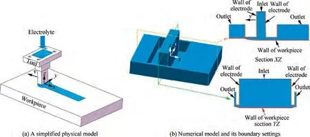
Fig. 2 Flow field analysis model and related boundary settings.

Table 1 Parameters of numerical modes.
In macro-EJM, large amounts of electrolytic products are generated in the machining area, and if they are not removed quickly, then they accumulate in the machining area and increase stray corrosion. Because the tool electrode should be fed forward, the machining at the back end of the tool is vital for the final surface quality during EJM.Therefore,enhancing product transport at the back end of the tool can improve the final surface quality. Above flow field simulation results show that tools A, B, and D might not promote rapid product removal at the back end of the tool, and products are more likely to accumulate in the machining area when using those tools, thereby increasing stray corrosion. By contrast, tool C not only decreased the low-velocity flow zone in the machining area but also increased the high-velocity one at the back end of tool.This can enhance the product transport at the back end of tool and improve the surface quality.
In addition, the electric field distribution of each tool was also studied in macro-EJM.Fig.4 presents the current density distributions on workpiece surface at section XZ for tools AD. As can be seen in Fig. 4, the current densities at the back end regions of tools A, B and D were obviously higher than that of tool C. This indicated that more products will be generated at the back end regions when using tools A, B and D,thereby increasing the difficulty of rapid product removal.Compared to tools A,B and D,tool C can weaken the electric field distribution at the back end region of tool, which can reduce the generation of products at the back end region of tool. This can promote the rapid removal of products and improve the surface quality.
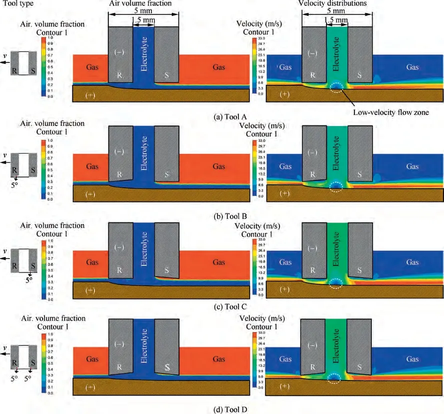
Fig. 3 Air volume fraction and electrolyte velocity distributions of different models.
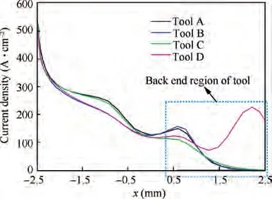
Fig. 4 Current density distributions on workpiece surface at section XZ for tools A-D.
3. Experimental
To validate the numerical results, we conducted a series of experiments using a self-developed setup as shown in Fig. 5.The cathode tool was fixed at the end of the spindle and could move in the x,y,and z directions under the control of the NC system. A DC power supply was used to provide the required external voltage and record the current response signal in real time. The electrolyte was kept pure by using a filter and at a constant temperature by using a cooler. In this study, the workpiece material was TC4 titanium alloy provided by the Baoji Titanium Industry Co., Ltd. (Shanxi, China). The main chemical composition of TC4 titanium alloy is listed in Table 2.Experiments were performed on each proposed tool to test its product transport capacity,and Table 3 gives the relevant processing parameters.To ensure experimental repeatability,each experiment was repeated three times.
The machined surfaces were imaged macroscopically using an optical microscope (DVM5000; Leika, Germany), and the three-dimensional profile and surface roughness of each groove were measured using a profilometer (VR5000; KEYENCE, Japan). Each specimen was imaged microscopically using a scanning electron microscope (SEM) (S-4800;Hitachi,Japan), and its composition was examined using an energydispersive X-ray spectrometer (EDX) (JSM-6360LV; JEOL,Japan).
4. Results and discussion
4.1. Surface quality
Fig.6 shows the macro morphologies of grooves machined by tools A-D, and Fig. 7 shows the microscopic structure and composition of each machined surface. As can be seen in Fig. 6, the surfaces machined by tools A, B, and D were gray-brown in color, whereas that machined by tool C was bright-white. This difference was mainly related to product accumulation. In macro-EJM, large amounts of electrolytic products are produced in the machining area, and if they are not removed quickly, then they adsorb on the surface and affect its gloss. The above finding indicates that the product transport capacity of tool C was greater than that of other tools. Decreasing the low-velocity flow zone in the machining area and increasing the high-velocity one at the back end of the tool promoted rapid product removal and reduced the product adsorption on the surface, thereby exposing the brightwhite substrate surface. Also, according to the EDX results in Fig.7,when using tools A,B,and D,the oxygen and carbon contents of each machined surface were 20.18wt% and 2.39wt%, 20.8wt% and 2.25wt%, and 17.05wt% and 1.39wt%,respectively, which were obviously higher than those (4.5wt% for oxygen and 0.27wt% for carbon) of the surface machined using tool C.In macro-EJM of titanium alloys,large amounts of oxides and carbides are generated in the machining area,so the EDX results indicate that the gray-brown surfaces were due mainly to the high content of oxides and carbides.
Additionally,excessive product adsorption on the surface is likely to aggravate the stray corrosion.As can be seen in Figs.6 and 7, when using tool A, the products cannot be removed quickly and serious stray corrosion occurred on the machined surface. This indicated that standard tool electrode cannot remove products quickly from the machining area,easily leading to serious stray corrosion and low surface quality.
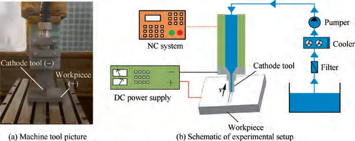
Fig. 5 Schematic of experimental setup.

Table 2 Main chemical composition for TC4 titanium alloy.
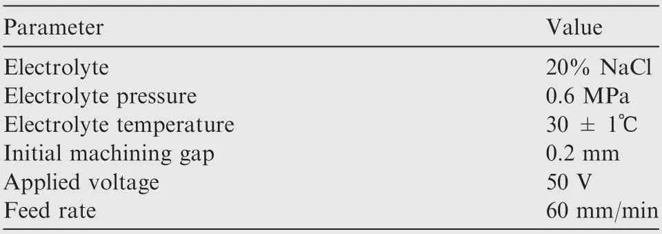
Table 3 Relative process parameters for experiments.
When using tool B,serious stray corrosion still occurred on the machined surface. This was mainly because the highvelocity flow zone at the back end of tool B was almost unimproved compared to that with tool A, thereby failing to promote rapid product removal at the back end of the tool. The increase of the low-velocity flow zone in the machining area also hindered rapid product removal, thereby resulting in excessive product adsorption on the surface and increased stray corrosion.
When using tool C, stray corrosion on the machined surface was obviously weakened. This was mainly because the back inclined end face not only decreased the low-velocity flow zone in the machining area but also increased the high-velocity one at the back end of tool. This promoted rapid product transport from the back end of the tool and reduced product adsorption on the surface, thereby weakening stray corrosion and improving surface quality.
When using tool D, serious stray corrosion occurred again on the machined surface. This was because part of the back end face of tool D was in direct contact with the electrolyte,causing severe secondary machining corrosion on the machined surface. Also, more products were produced at the back end of the tool during macro-EJM with the participation of the back end face in the machining, thereby making rapid product removal more difficult. This resulted in excessive product adsorption on the surface,thereby increasing stray corrosion and reducing surface quality.
Fig.8 shows the values of the surface roughness(R)of the surfaces machined using tools A-D.As can be seen,the surface machined using tool C had the lowest value of surface roughness(R=1.21 μm),suggesting that the back inclined end face can promote rapid product removal and improve surface quality. Also, compared to tool A, the surfaces machined by tools B and D had lower values of surface roughness,indicating that changing the end structure of tool electrode can improve the surface quality to a certain extent.
The above experimental results show that the tool with a 5°back inclined end face can promote rapid product removal and improve surface quality. Increasing the back end inclination angle might further enhance the product transport capacity at the back end of tool. To study the influence of the increase of back end inclination angle on the surface quality,tools with a 10° back inclined end face (tool E) and a 15° back inclined end face (tool F) were tested under comparable conditions.Fig.9 shows the macro morphologies and Rvalues of surfaces machined using tools E and F. As can be seen, those surfaces were gray-brown in color, indicating that products were not removed quickly and adhered to the surfaces. This increased the stray corrosion and lowered the surface quality(R= 1.467 μm for tool E and 1.413 μm for tool F). To explain the experimental results further, the flow and electric fields of tools E and F were analyzed.Fig.10 shows the air volume fraction and electrolyte velocity distributions of tools E and F,and Fig.11 shows the electric field distribution for tools C, E, and F. As can be seen in Fig. 10, with increasing back end inclination angle, it was easier for the back end face to make direct contact with the electrolyte,thereby causing severe secondary machining corrosion on the machined surface. In addition, it can be seen in Fig. 11, the current densities at the back end region of tools E and F are obviously larger than that of tool C. This indicated that more products were produced at the back end of tools E and F with the participation of the back end face in the machining, thereby making rapid product removal more difficult. This led easily to excessive product adsorption on the surface and increased stray corrosion. Consequently, increasing the back end inclination angle did not improve the surface quality. This indicated that rapid product removal was possible only when the back end inclination angle was within a certain range, thereby improving surface quality.
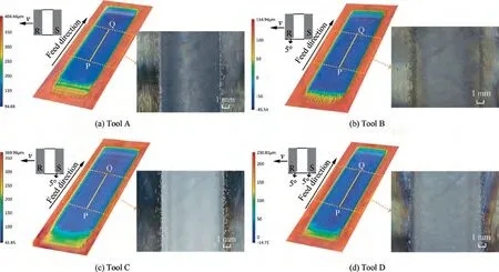
Fig. 6 Macro morphologies of grooves machined by tools with different end structures.
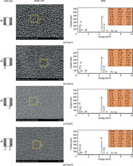
Fig. 7 Micro morphologies and components of surfaces machined using tools A-D.
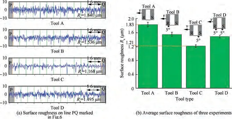
Fig. 8 Values of surface roughness of surfaces machined using tools A-D.
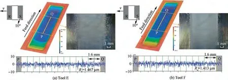
Fig. 9 Macro morphologies and Ra values of surfaces machined using tools E and F.
4.2. Cross-section profiles and material removal rates
Fig. 12 shows cross-section profiles of grooves machined by tools A-D, and Fig. 13 shows the corresponding machining depths and MRRs. As can be seen in Fig. 12, the crosssection profile of the groove machined by tool C was smoother compared to other tools. This was because products were removed quickly when using tool C, thereby promoting uniform dissolution of the workpiece surface material. Also, as can be seen in Fig.13,tool C resulted in the greatest machining depth and highest MRR. This was mainly because products can be removed rapidly using tool C, thereby exposing more fresh matrix materials in the machining area compared to other tools. This promoted the dissolution of more matrix materials, thereby improving the machining depth and MRR.
Fig.14 shows the machining currents for grooves machined by tools A-D.As can be seen,the machining current for tool C was the largest. This can be explained that using tool C can promote the rapid product removal from the machining area,thereby increasing the electrolyte conductivity in the machining area. As given by
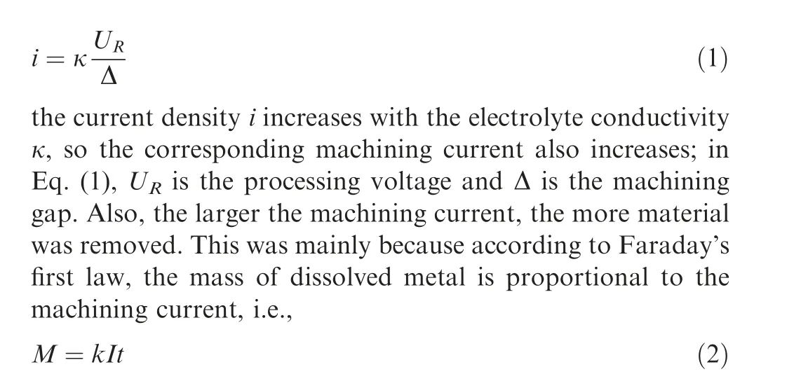
where M is the mass of metal dissolved at the anode, k is the mass electrochemical equivalent, I is the machining current,and t is the machining time. Therefore, tool C can produce greater machining depth and higher MRR compared to other tools.
4.3. Effect of product adsorption on subsequent processing
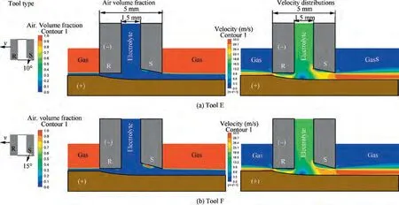
Fig. 10 Air volume fraction and electrolyte velocity distributions for tools E and F.
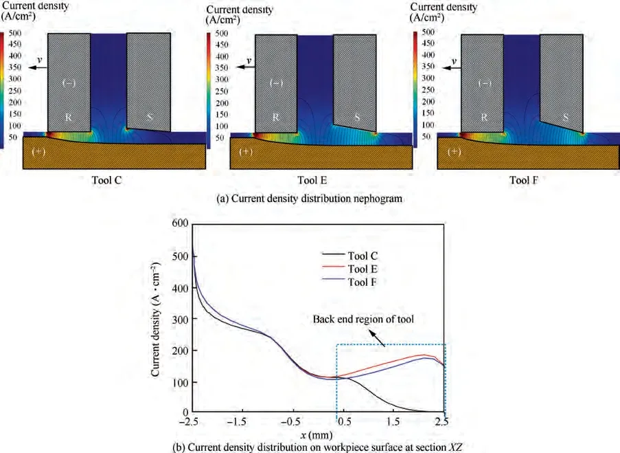
Fig. 11 Electric field distributions for tools C, E, and F.
To satisfy the requirements of certain groove depths, it is sometimes necessary to repeat the processing path several times.However,if the machining products cannot be removed quickly in one processing path, then they adsorb on the machined surface. As indicated by the EDX results in Fig. 7,the products comprised mainly highly insulating oxides and carbides,so excessive products adsorbing on the surface during one processing path might affect the subsequent processing.To investigate the effect of product adsorption on subsequent processing,tools A and C were selected for deep groove machining with two processing paths.Fig.15 illustrates the schematic diagram of the deep groove machining. The macro morphologies and cross-section profiles of deep grooves machined using tools A and C are shown in Fig. 16, and the corresponding machining depths and MRRs are presented in Fig. 17.

Fig. 12 Cross-section profiles of grooves machined by tools AD.
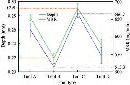
Fig. 13 Machining depths and MRRs of grooves machined by tools A-D.
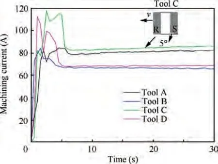
Fig. 14 Machining currents for grooves machined by tools A - D.

Fig. 15 Schematic of deep groove machining.
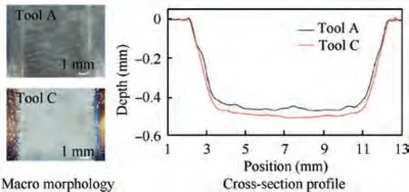
Fig. 16 Cross-section profiles of deep grooves machined using tools A and C with two processing paths.
As can be seen in Figs.16 and 17(a),the machining depth of the deep groove using tool C was larger than that using tool A.The increment of the machining depth of the deep grooves between tools C and A was 7%, which was larger than that(5%) of single processing path between tools C and A. Also,as can be seen in Fig. 17(b), the increment of the MRR of the deep grooves between tools C and A was 14%, which was obviously larger than that (8%) of single processing path between tools C and A.These findings indicated that reducing product adsorption on the surface in the first path can promote the material removal in the second path. Thus, because of its rapid product transport, tool C produced greater machining depth and higher MRR during deep-groove machining compared to tool A, thereby improving the machining efficiency.
Fig. 18 shows the average currents of deep groove machining using tools A and C. As can be seen, the average current for tool C was higher than that for tool A in both the first and second paths. Also, the increment of average current(10%) between tools C and A in the second path was higher than that(5%)in the first path.This suggested that rapid product removal in the first path can increase the average current in the second path.This might mainly be because compared to tool A, the reduction of insulating products adsorbing on the machined surface decreased the surface impedance when using tool C, thereby increasing the average current. According to Faraday’s first law, increasing the machining current can promote more matrix material removal. Thus, greater machining depth and higher MRR during deep groove machining were obtained using tool C.
4.4. Step-over
Multiple contour-parallel tool paths should be used when machining wider grooves or planes. In multiple contourparallel tool paths, bottom flatness is a problem that must be addressed. Defined as the displacement between two tool paths,the step-over has a significant effect on bottom flatness.If the step-over is small,then the electrode overlap is high and so too much material of the first tool path might be removed by the second tool path. By contrast, if the step-over is large,then the electrode overlap is low or even non-existent and so too little material of the first tool path might be removed by the second tool path. Removing too much or too little matrix material of the first tool path has a negative impact on bottom flatness, so a proper step-over is needed to produce a flat bottom. Tool C was selected for the study of step-over. To find a proper step-over value,five initial step-over values(7.8,8,8.2,8.4, and 8.6 mm) were examined by conducting two contourparallel tool paths, as shown in Fig. 19. As can be seen, when the step-over was the lowest (7.8 mm), the electrode overlap was 0.2 mm; when the step-over was increased to 8 mm, the electrode overlap was zero; when the step-over was increased to 8.2, 8.4, or 8.6 mm, the electrode overlap was nonexistent. However, despite the electrode overlap was nonexistent when the step-over exceeded 8 mm, the groove sidewall region of the first tool path was still in the machining area of the second tool path, so the material at the groove sidewall region of the first tool path can be still removed by the second tool path.
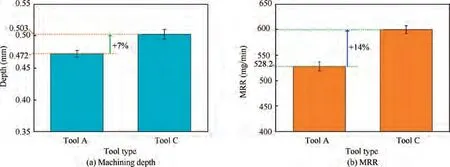
Fig. 17 Machining depths and MRRs of deep grooves machined by tools A and C.
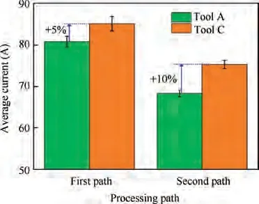
Fig. 18 Average current for deep grooves machined using tools A and C.
Fig. 20 shows the groove profiles for different initial stepover values by using two contour-parallel tool paths. As can be seen, when the step-over was 8.2 mm (see Fig. 20(c)), the best flat bottom with a height difference (Δh) of 0.027 mm was obtained. When the step-over was less than 8.2 mm (see Fig. 20(a) and 20(b)), obvious concavity appeared on the groove bottom and grew with decreasing step-over, leading to poor bottom flatness. This was mainly because too much material of the first tool path was removed by the second tool path with decreasing step-over. By contrast, when the stepover exceeded 8.2 mm (see Fig. 20(d) and 20(e)), convexity appeared on the groove bottom and grew with increasing step-over, leading again to poor bottom flatness. This was mainly because too little material of the first tool path was removed by the second tool path with increasing step-over,resulting in more matrix material remaining at the groove sidewall region of the first path.
In addition, tool C with a step-over of 8.2 mm was used to process a plane.Fig.21 shows the macro morphology and profile of the plane machined by using multiple contour-parallel tool paths. As can be seen, a plane with a depth (d) of 0.285 mm and a bottom height difference (Δh) of 0.03 mm was fabricated successfully. The bottom flatness of plane was about 0.03 mm.
5. Conclusions
In this study, tools with a standard flat end face, a front inclined end face, a back inclined end face, and both front and back inclined end faces were proposed for macro-EJM of TC4 titanium alloy. The flow field distribution of each tool was analyzed numerically,and experiments were conducted to validate the simulation results. The surface quality, crosssection profile,and MRR for machined grooves were also analyzed in detail. Also examined was the effect of product adsorption on subsequent processing. In addition, the stepover during the machining of wider grooves or planes was investigated in depth. The main conclusions of this work are summarized as follows:
(1) The flow field simulation results showed that the tool with a 5° back inclined end face not only decreased the low-velocity flow zone in the machining area but also increased the high-velocity one at the back end. This can enhance the product transport at the back end of the tool and improve surface quality. By contrast, the tools with other end structures cannot promote rapid product removal, which are more likely to cause the accumulation of products in the machining area and increase the stray corrosion.
(2) The experimental results showed that the tool with a 5°back inclined end face produced a relatively smooth bright-white machined surface. However, because of the participation of the back end face of tools in ECM, the groove surface quality cannot be improved further by increasing the back end inclination angle to 10°or 15°.Also,compared to tools with other end structures,the one with a 5°back inclined end face produced the greatest machining depth and highest MRR.
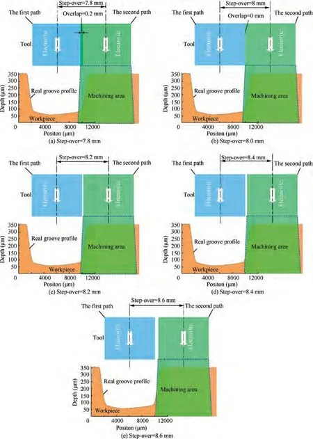
Fig. 19 Schematic of different step-over values using two contour-parallel tool paths.
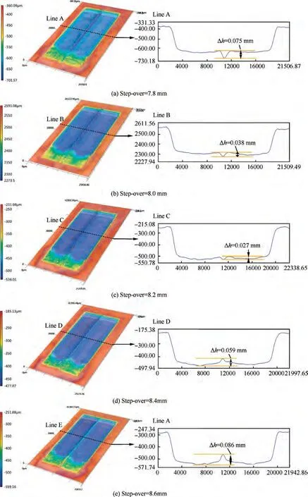
Fig. 20 Profiles of grooves for different initial step-over values using two contour-parallel tool paths.

Fig. 21 Macro morphology and profile of plane machined using multiple contour-parallel tool paths.
(3) Rapid product transport can promote the material removal during subsequent processing. When using the tool with a 5° back inclined end face, the products were removed quickly in the first processing,thereby promoting the removal of more matrix material in the subsequent processing. The machining depth and MRR during deep groove machining using the tool with a 5°back inclined end face were respectively 7% and 14%higher than those produced using a standard tool electrode.
(4) Compared to other step-over values, the lowest bottom height difference of 0.027 mm was obtained when the step-over was 8.2 mm. Finally, using the tool with a 5°back inclined end face and a step-over of 8.2 mm, a plane with a depth of 0.285 mm and a bottom height difference of 0.03 mm was fabricated successfully by using multiple contour-parallel tool paths.
The authors declare that they have no known competing financial interests or personal relationships that could have appeared to influence the work reported in this paper.
This work was supported by the National Natural Science Foundation of China (No. 91860208) and the National Natural Science Foundation of China for Creative Research Groups (No. 51921003).
