Tensile properties analysis of CFRP-titanium plate multi-bolt hybrid joints
Yanping ZHENG, Chaoyu ZHANG, Ying TIE, Xu WANG, Mingkun LI
School of Mechanical and Power Engineering, Zhengzhou University, Zhengzhou 450001, China
KEYWORDS CFRP laminate;Finite element model;Hybrid (bonded/bolted)joint;Multi-bolt;Tensile properties
Abstract Hybrid joints have better tensile properties than pure bonded and bolted bolts, and are increasingly used in the aerospace field.Tensile tests are carried out for the Hybrid Bonded/Bolted(HBB)joints of Carbon Fiber Reinforced Polymer(CFRP)laminate and titanium alloy plate under different bolt numbers,and the corresponding load–displacement curves are obtained.At the same time, based on Continuum Damage Mechanics (CDM) theory, which is derived from 3D Hashin failure criteria, and a Cohesive Zone Model (CZM), the tensile strength prediction model of the composite laminate-titanium alloy plate multi-bolted HBB joint was established,and the numerical simulation results were in good agreement with the experimental height,which validate the feasibility of the model. The difference in the bearing capacity of HBB joints under different numbers of bolts is compared and analyzed. On this basis, the influence of inter-bolt distance on the tensile properties of the HBB joints is explored.The results show that the double-nail HBB joints can effectively improve the end warpage and low bearing capacity of the single-nail HBB joints. The tensile failure load of the double-nail HBB joints under the standard lap width (30 mm) is 82.6% higher than that of the single nail,the tensile failure load of the three-bolt HBB joints is 34.1%higher than that of the double nail.For the three-bolt HBB joint,the joint strength is controlled by the adhesive and the external bolt, while the internal bolt is redundant, the hybrid joint can be simplified by reducing the middle bolt. The inter-bolt distance has a great influence on the failure load of the hybrid joint. Increasing the inter-bolt distance can effectively improve the bearing capacity of the structure.
1. Introduction
Carbon Fiber Reinforced Polymer (CFRP) has high specific strength, better mechanical properties, longer fatigue life, corrosion resistance and lighter weight. The use of modern aircraft structures (such as wing skins, hoods and fuselages)continues to increase.On the other hand, joints of dissimilar materials are gradually increasing in aerospace applications,such as aluminum and CFRP bonding. CFRP/titanium alloy TC4 joints have been used in aircraft and are now used in airframes. Recently, CFRTP/TC4 joints have been used in aircraft wing boxes and cabins. Dissimilar material connection joints have excellent connection performance, fatigue life and impact resistance.
In the design of aircraft structures, structural integrity is always the goal pursued by designers to improve structural efficiency.The mechanically fastened joints (bolted or riveted) will cause stress concentration around the hole and reduce structural integrity.Adhesive joints can eliminate most of the stress concentration,but the adhesive layer is very sensitive to environmental factors such as humidity and temperature, which will greatly reduce the structural reliability,1so adhesive joints have not been widely used in the basic structure of aircraft. In order to obtain higher performance joints, a combination of mechanical joints (bolts, rivets, etc.)and adhesives are used, namely hybrid joints.Hybrid Bonding/Bolting (HBB)joints can overcome the potential disadvantages of pure bonded and bolted joints.
Chishti et al.conducted an experimental study on the connection of countersunk head bolts in composite laminates,and studied the effects of torque, bolt fit clearance and counterbore height ratio on damage propagation and joint strength.Li et al.studied the effects of overlap length,the thickness of the adherend and the width of the overlap on the tensile properties of CFRP joints through experiments.The strength of the bonded joint was found to be increased with the adherend thickness, overlap length and width for brittle adhesive. Sun et al.established a three-dimensional finite element model based on the strain-based 3D Hashin failure criterion to explore the mechanical properties of single-lap bonded joints,and conducted experimental studies on different overlap lengths,adherend widths,and stacking sequences of the joints.The reliability of the numerical simulation is verified.
Some studies have shown that, compared with separate mechanical joints and adhesive joints, hybrid joints perform better in terms of static strength and fatigue properties.Kweonused two types of adhesives (film and paste) and found that when the strength of the bolted is lower than the strength of the adhesively bonded, the bolt has little effect,and the hybrid joint has the same strength as the adhesive film joint.However,if a paste adhesive with lower strength is used,the strength of the hybrid joint is greatly improved compared to the mechanically fastened joints and the adhesive joints.Ref. 24 investigated the tensile strength of bolted, adhesive and HBB joints through experiments, and found that the bolt in the hybrid joint can enhance the tensile performance after the adhesion failure,and the tensile strength of the hybrid joint is the highest,the tensile strength of adhesive joints is the lowest. Di Franco et al.investigated the tensile strength of the CFRP and aluminum plate’s sticky riveting hybrid joint.They examined the aluminum plate connected to the CFRP laminate and found that the hybrid joint can potentially improve the joint tensile strength,stiffness and energy absorption.Esmaeili et al.has studied the effect of bolt clamping force on the fatigue life of double lap simple bolted and HBB joints have been studied both experimentally and numerically. Experiments show that the hybrid joints have higher fatigue life in comparison with the simple bolted joints. In addition, the clamping force generated by torque tightening has a positive effect on the fatigue life of both simple and hybrid joints.
Several investigations discussed the design parameters of HBB joints, such as adhesive thickness, adherend thickness,clamping force, overlap length, adhesive modulus, and bolt hole clearance. Raju et al.developed a three-dimensional finite element model to investigate the influence of interference fit on the HBB joints. Research shows that the interference fit can transfer the load immediately after the joint is loaded,and the strength of the interference fit joint is about 10% higher than that of the clearance fit joint. Li et al.discussed the parameters of the system. Use numerical model to analyze the influence of design parameters on HBB joints tensile properties.It was found that bond modulus showed positive effects on the tensile properties of HBB joints. The use of highstrength adhesives with low modulus is a key method to improve the initial damage load and joint bond strength.High-strength bolts can effectively improve the pressurebearing strength of the bolt hole and the energy absorption capacity of the joint. Lopez-Cruz et al.investigated the effects of adhesive thickness, adherend thickness, adhesive modulus and bolt hole clearance through experiments. The results show that the thickness and adhesive modulus of the adherend are the most important design parameters that have a positive effect on the strength of the HBB joints,the bolt hole gap shows a negative effect.
At present,most researches on HBB joints compare the static strength and fatigue properties of hybrid joints,mechanical joints,and adhesive joints through experiments or simulations,and investigate the influence of structural parameters on the tensile properties of hybrid joints. However, most of the researches is on the hybrid joints of a single bolt, and there are few investigations on the tensile behavior of multi-bolt hybrid joints. In this paper, CFRP and titanium alloy plates are used as the research object,and are combined with numerical simulation and experiments to analyze the tensile behavior of the multi-bolt hybrid joints, and compare the load-bearing capacity of the hybrid joint under different bolt numbers.And further investigate the influences of inter-bolt distance and bolt end distance on the tensile properties of the joints.
2. Experimental
2.1. Test piece preparation
Single-shear HBB joints with one or two bolts were designed according to ASTM-D5961, as shown in Fig. 1. The bolt hole diameter is 5 mm. For three bolts, the same geometry as the two bolts (ASTM-D5961) is used, except that the joint is expanded to a third bolt with the same inter-bolt distance and end distance.The end distance refers to the distance from the outer edge of the joint member to the center of the outer bolt, and is kept constant at 15 mm, which means that the overlap length of the hybrid joint is equal to the outermost inter-bolt distance +30 mm. Considering that the test conditions cannot accurately apply the bolt clamping force, the manual tightening of the bolts in the test is only for contact.
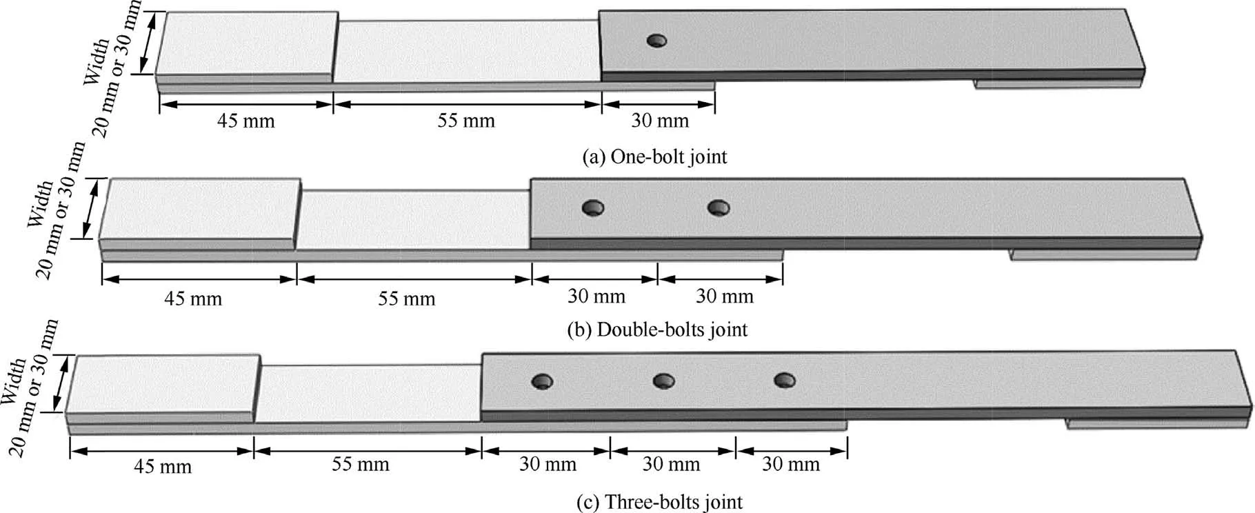
Fig. 1 CFRP-titanium hybrid bonded-bolted joints.
The test uses T300/7901 CFRP laminates, the single layer thickness of the laminate is 0.15 mm, the nominal thickness is 3.6 mm, and the stacking sequence is [45/0/–45/90]. For titanium alloy (TC4) plate and titanium alloy (TC4) bolts,the material performance parameters are as follows: density ρ = 4510 kg/m, Poisson’s ratio ν = 0.34, shear strength τ ≥655 MPa,tensile strength σ≥1103 MPa,tensile modulus E=110 GPa, bolt diameter is 5 mm.The composite material plate and the titanium alloy plate were cut by the HSQ1210 water jet cutting machine to obtain test specimens corresponding to the size of Fig.1.The adhesive is LJM-200 type adhesive film with a thickness of 0.2 mm.After the initial preparation of the test piece, it needs to be heated and cured in a HOCZH60A vacuum oven and maintained at a curing temperature of 120 °C for 90 min. Table 1 is the material parameters of laminated board T300/7901,and Table 2 is LJM-200 film parameters.
2.2. Experiment method
The tensile test of the specimens was carried out on the universal testing machine WDW-300,with 3 specimens tested in each group.Setting aluminum plates with the same thickness as thematerial plate at both ends of the test piece as clamping ends can reduce the eccentric effect of the test sample during the stretching process. During the tensile test, the specimen is clamped on the tensile testing machine, the lower chuck is completely fixed, and the upper chuck stretches the specimen at a rate of 2 mm/min. The set-up for the tensile test is shown in Fig. 2.
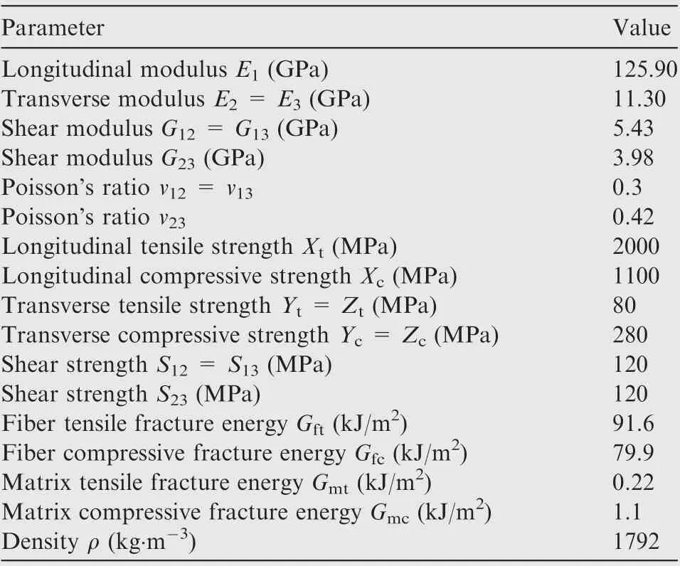
Table 1 Mechanical properties of CFRP laminate T300/7901.30
3. Numerical simulation method
3.1. Failure criteria and damage evolution laws
In order to determine the final failure of composite laminates caused by intra-layer damage, numerical simulation adopted the 3D Hashin failure criterion. The main reason to choose the Hashin failure criterion is that it has been successfully used in many Finite Element (FE) simulations to predict the progressive failure behavior of composite materials. In addition,this failure criterion includes four separate failure modes:fiber and matrix failure, and each includes tensile and compression modes.Each failure mode can be represented by e(i=ft;fc;mt;mc), when the evalue of a material point is 1,the point begins to fail. The four different failure modes are given as follows:
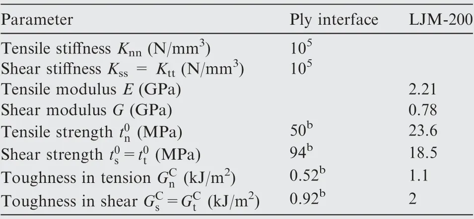
Table 2 Mechanical properties of adhesive film LJM-200.19
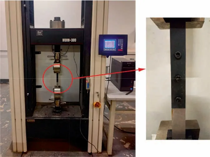
Fig. 2 Specimen and test set-up.
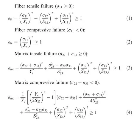
where σ, σ, and σare normal stress components along longitudinal, transvers and thickness directions, respectively;σ, σ, and σare shear stress components.
The damage criterion only predicts the beginning of the damage of the composite material. Once the damage occurs,further loading will cause the stiffness of the material to decrease. Exponential continuous damage variables are used to describe the progressive damage of fiber reinforced materials.The three-dimensional material damage constitutive model of CFRP laminates is

where σ and ε represent stress and strain, respectively; C(d) is the stiffness matrix representing the damage state.
The continuous damage variable is represented by d,where d, d, d, and dare the damage variables of the failure modes of fiber stretching,fiber compression,matrix stretching,and matrix compression respectively. The value range is [0, 1],d=0 means that no damage has occurred to the material; at that time,d=1 means that the material has completely failed.When the material point fails, its stiffness matrix will be reduced. The expressionsare

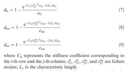
In order to predict the failure of composite materials, the 3D Hashin criterion has been implemented in ABAQUS/Explicit using the terminology of the user subroutine VUMAT,which includes the failure criterion, the element with reduced stiffness and the element deletion criterion. In each loading step, the stress at each integration point in the composite laminate is calculated in this user subroutine.Then,the failure criterion is used to evaluate whether any damage has occurred, and the elasticity of specific elements must be reduced according to the failure mode.
3.2. Interlayer and adhesive layer damage theory
Delamination mainly occurs at the interface between composite layers, obviously, delamination is not considered in the 3D Hashin failure criteria. Therefore, bilinear Cohesive Zone Models(CZMs)are used to simulate delamination and adhesive layer damage of the composite laminate.CZMs follow the traction separation law,which have been integrated into ABAQUS finite element software as a cohesive module.Fig.3 is the bilinear constitutive model of the cohesive element, the corresponding separations are denoted by δ, δand δ. The nominal strains can be defined as

where Tis the initial thickness of the element;δ is the separation displacement vector, δ = [δ, δ, δ].
A cohesive force unit of 0 thickness is inserted between the laminate layers by the offset method, and the adhesive layer establishes a cohesion unit with a thickness of 0.2 mm.The initial damage of the COHESIVE element in the interlayer and the adhesive layer is judged by the second nominal stress criterion:
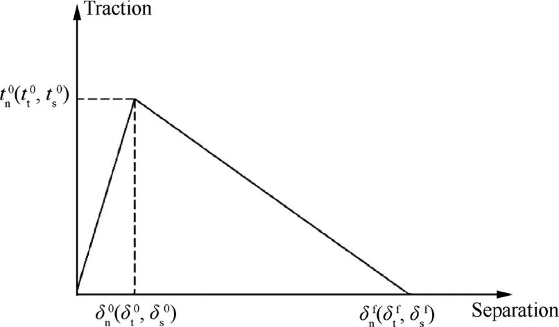
Fig. 3 Bilinear traction-separation law.
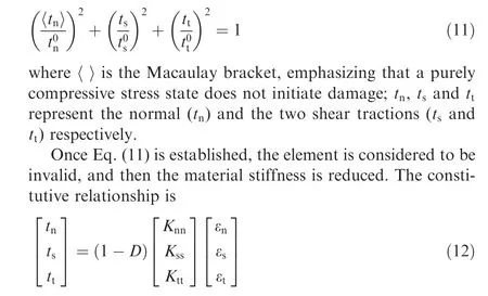
where D (0 ≤D ≤1) is the damage variable, and D increases from 0 to 1, which means the material evolves from initial damage (equal to 0) to final failure (equal to 1). The output variable SDEG of ABAQUS represents the overall scalar stiffness degradation of the viscous element, and the value ranges from 0 (undamaged material) to 1 (complete failure).
The final failure displacement is controlled by the fracture energy, which can be calculated using the BK criterion:

where G, G, and Gs are the total, normal and shear critical fracture energy, respectively; Gis the dissipated energy in the out-of-plane direction; Gis the total dissipated energy in all three directions; η is related to material parameters,η = 1.45.
3.3. Finite element model
ABAQUS is used to establish the three-dimensional model of the double-nail and three-nail hybrid joints, and the VUMAT subroutine is used to dynamically solve the model. Fig. 4 is a three-dimensional finite element model of a double-nail hybrid joint, which is divided into 24 layers and corresponding to the layup along the thickness direction of the composite laminate.C3D8R solid elements with enhanced hourglass control are used to model the thickness of each layer, and the mesh is refined in the bonding and bolting areas to improve the accuracy of stress and failure simulation. Through the offset method, a zero-thickness cohesive layer interface is inserted between every two plies of the laminate, and the interlayer and adhesive layer unit types are both COH3D8.
When simulating the bolt connection, the method of Ref. 37 ignores the influence of the thread, and simplifies the bolt and the nut into a whole, and the bolt uses the C3D8R unit. The assembly method is adopted for modeling. The glue layer and the laminate and the titanium alloy plate need to be bound by tie definition. The contacts between the bolt head and the laminate, the bolt head and the titanium plate, the screw and the hole are defined by the master–slave contact algorithm, and the bolt head and the screw are selected as the main surface. The type of slip is finite slip, the tangential behavior of contact uses a penalty function(Penalty),the friction coefficient of the penalty function is set to 0.15, and the normal behavior is calculated by the hard contact method.In the test, the bolts were tightened manually and only used for contact, so the bolt pre-tightening force was not applied during the simulation process.
Boundary constraints are imposed on the model,one end of the titanium alloy plate is completely fixed,one end of the laminated plate is coupled with a Reference Point(RP),and a displacement load in the U1 direction is applied to the reference point. A completely fixed boundary condition is applied at the left end of the titanium alloy plate, and the degree of freedom except for the U1 direction is fixed at the right end of the composite material. A displacement load is applied in the U1 direction, and the displacement load is loaded with a smooth amplitude. Set the reference point along the vertical line in the thickness direction at 10 mm from the right end of the composite plate,couple the right end surface of the composite plate and the reference point together, select the reaction force and displacement of the reference point in the history output to construct the load of the model displacement curve.
4. Results and discussion
4.1. Hybrid bonded/bolted joints behavior with two bolts
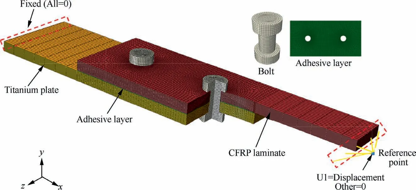
Fig. 4 3D finite element model of CFRP-titanium hybrid bonded-bolted joint.
Due to the end warpage of the single HBB joints,the end peeling stress is relatively large.And the adhesive layer will quickly fail under the influence of the peeling stress, resulting in a decrease in the structural bearing capacity. The hybrid joints of double snails can reduce end warping, and the increase in the number of bolts can improve the load transfer ability of the hybrid joints. It can be seen from the load–displacement curves of single-nail hybrid joints under different widths in Fig. 5 that the failure load of a 20 mm-wide single-nail hybrid joint is 12.13 kN,and the failure load of a 30 mm-wide singlenail hybrid joint is 15.17 kN. It can be concluded from Fig. 6 that when the width is 20 mm, the bearing capacity of the double-nail hybrid joint is increased by 79.1% relative to the single-nail joint;when the width is 30 mm,the bearing capacity of the double-nail hybrid joint is increased by 82.6%relative to the single-nail joint.
Fig. 6 shows the test limit failure load of mixed joints at 20 mm and 30 mm width under different bolt numbers. Due to some errors caused by equipment and human factors in the test process, the test data will fluctuate to a certain extent,and the mixed joints will inevitably exist during the preparation process. Glue and the inability to accurately grasp the degree of bolt tightening have led to large test data.Of course,there are also cases where the numerical value is too small.During the process of cutting holes and tightening the bolts of the composite plate,certain damages are caused to the composite plate. In terms of size, the data deviation value of onebolt is relatively small. Relatively speaking, the deviation of three-bolts is slightly larger. Because three-bolts need to be drilled three holes, the error accumulation will be larger, but overall, the deviation of the test result data of the specimen is within an acceptable range.

Fig. 5 Load–displacement curves of single nail HBB joints under different widths.
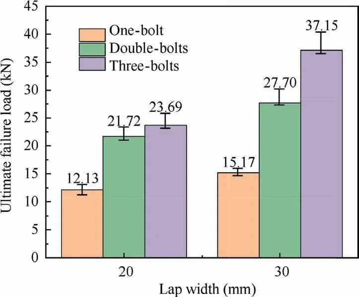
Fig.6 Ultimate failure load of joints under different lap widths.
Fig. 7 shows the load–displacement curves of the doublebolt hybrid joints with widths of 20 mm and 30 mm. When the width is 20 mm, the error of the test failure load (21.72 kN) and the simulated failure load (22.97 kN) is 5.8%; when the width is 30 mm, The error of the test failure load (27.70 kN) and the simulated failure load (29.16 kN) is 5.3%; the error of both is less than 10.0%, which verifies the validity of the numerical simulation method. It can be seen from Fig. 6 that the failure load of the double-nailed joint with a width of 30 mm is increased by 27.5% compared with that of the double-nailed joint with a width of 20 mm.The increase in the bonding area increases the failure load of the joints.
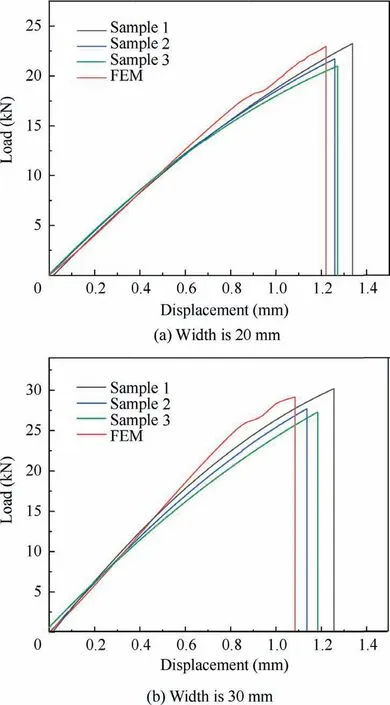
Fig. 7 Load–displacement curves of double-bolt hybrid joints under different widths.
Fig.8(a)is the failure mode of the double-bolt hybrid joint test, Fig. 8(b) is the damage mode when the laminate matrix fails in tension, Fig. 8(c) is the failure mode of the adhesive layer, compare Fig. 8(a) and (b) to see the final failure form of the hybrid joint is that the composite plate breaks from the first bolt at the upper end. The test and simulation results are consistent;from Fig.8(c),it can be seen that when the joint fails, the adhesive layer on the outer ends of the two bolts has been completely failured, the adhesive layer between the two bolts did not completely fail. This is because the existence of the bolts at both ends prevents the peeling stress from spreading to the center of the overlap,reduces the damage to the middle adhesive layer, and the two bolts bear most of the load transfer, so the intermediate layer is not completely failed.
4.2. Hybrid bonded/bolted joints behavior with three bolts
Fig. 9 shows the load–displacement curves of the three-nail hybrid joints with widths of 20 mm and 30 mm. When the width is 20 mm, the simulation failure load (25.03 kN) of the three-nail hybrid joints is compared with the test (23.69 kN),the relative error is 5.7%;when the width is 30 mm,the relative error between the simulation results (39.03 kN) and the test data (37.15 kN) of the three-nail hybrid joints is 5.1%; the errors of both are less than 10.0%, which verifies the validity of the numerical simulation method.
It can be seen from Fig.6 that the failure load of the threenailed joints with a width of 30 mm is increased by 56.8%compared with that of the three-nailed joints with a width of 20 mm. The increase in the overlap width increases the failure load of the joints. Compared with the 27.5% increase of the double-nail joints in Section 4.1, it can be seen that the failure load of the three-nail hybrid joints is more sensitive to the overlap width than the double-nail joints.
It can also be seen from Fig.6 that when the overlap width is 20 mm,the failure load of the double-nail joints is 21.72 kN,the failure load of the three-nail joints is 23.69 kN, and the load-bearing capacity is increased by 9.1%; when the overlap width is 30 mm, the failure load of double-nail joints fails is 27.70 kN, the failure load of the three-nail joints is 37.15 kN,and the load-bearing capacity is increased by 34.1%;compared to the 9.1% increase in the width of 20 mm, it can be obtained that it is more appropriate to increase the number of bolts at the width of 30 mm to improve the load-bearing capacity of the joints.
Fig. 10 is the failure diagram of the three-nail hybrid joint with a width of 20 mm. It can be seen that the fracture occurred at the first bolt at the upper end. The main reason is that the tensile failure of the matrix is relatively serious,and the two bolt holes at the lower end are hardly damaged.Fig. 10(c) is a cloud diagram of adhesive layer damage. It can be seen that all the upper adhesive layer of the first bolt has failed, and the lowest adhesive layer is also slightly damaged. There is no damage to the adhesive layer between the second bolt and the third bolt. That is, this part of the glue layer does not transmit any load during the stretching process.In order to make this part of the glue layer work, consider removing the middle bolts and keep the overlap area unchanged.
4.3. Comparison of different joint forms
A 20 mm wide double-bolt sample is used as the research object, and the tensile properties of pure glued joints, bolted joints and hybrid joints under this size are compared. The load–displacement curves is shown in Fig. 11.
It can be seen from Fig.11 that the failure load of the pure bonded joint is 17.88 kN, the failure load of the pure bolted joint is 16.29 kN, and the failure load of the HBB joint is 22.97 kN.The HBB joint has higher connection strength under the same joint size.Ref.16 pointed out that the HBB joint with clearance fit is like a simple combination of pure bonding and pure bolted joints, while neat HBB joints are not.In addition,the interference fit is more conducive to the HBB joint,and the proper interference fit can make the bolt and the adhesive layer work at the same time, which can maximize the advantages of the HBB joint.The test comparison of the tensile properties and fatigue life of the three types of joints will be a direction of our follow-up research.
4.4. Effect of inter-bolt distance on tensile properties of joints
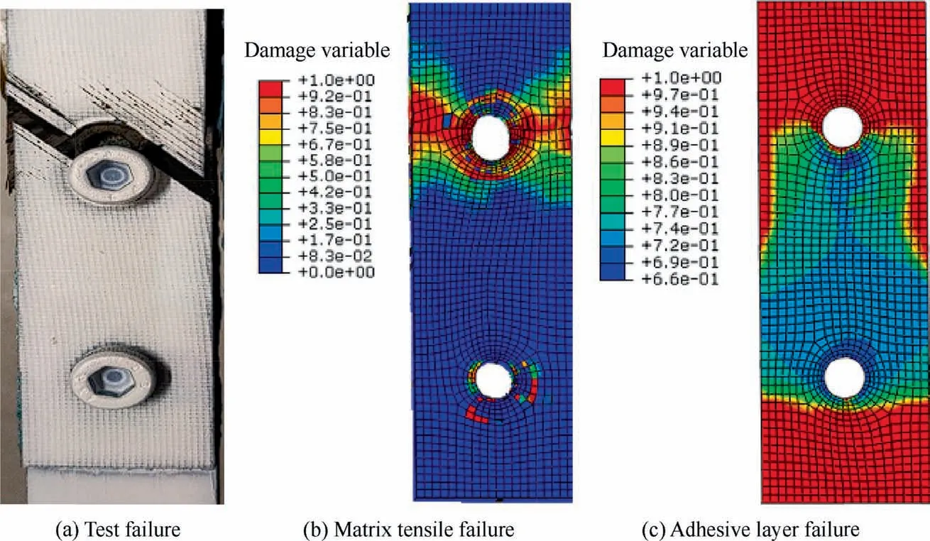
Fig. 8 20 mm wide double bolt hybrid joint failure.
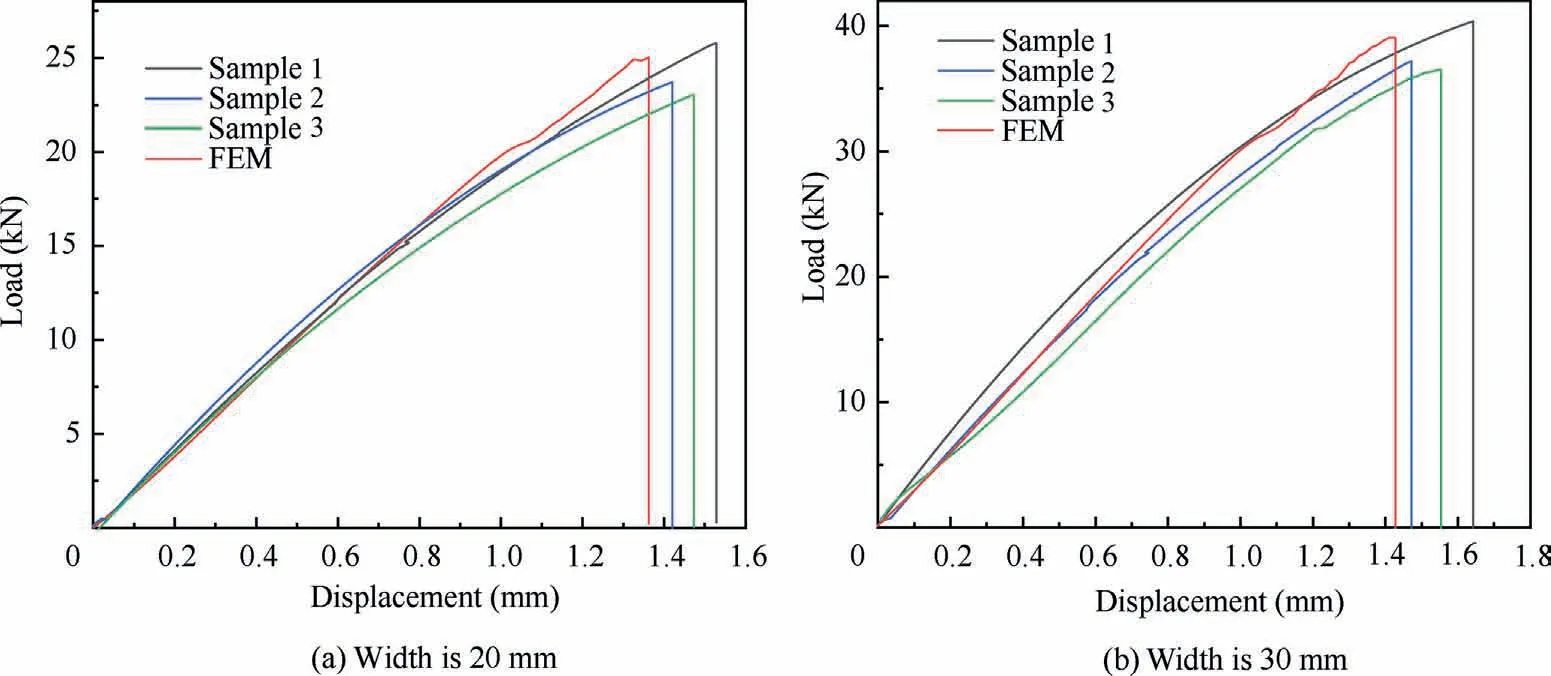
Fig. 9 Load–displacement curves of three-bolt hybrid joints under different widths.
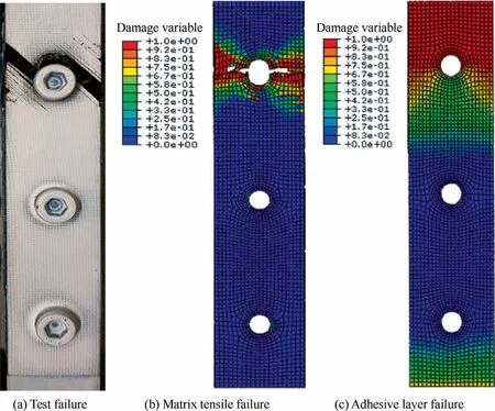
Fig. 10 20 mm wide three nail hybrid joint failure.
In order to investigate the effect of double nail arrangement on structural failure load, the width of 20 mm and 30 mm plates are taken as the research objects, and numerical simulation analysis is carried out. The distance between the external bolt and the end is kept unchanged at 15 mm, and only the interbolt distance is changed,as shown in Figs.12 and 13.A represents the standard three-bolt arrangement, and the outermost bolt spacing is 60 mm; B represents the inter-bolt distance is 60 mm, which is equal to the distance between two external bolts of a conventional three-bolt joint.The load–displacement curves in Figs.12 and 13 show that double-bolts with a spacing of 60 mm have almost the same strength as standard threebolts. These results show that for the three-bolt hybrid joint,the strength is controlled by the adhesive and the outer bolts,while the inner bolts are redundant. These results are particularly important for the design of large structures with multiple rows and columns. It can simplify mixed joints.
Comparing and analyzing the Groups B, C, D, and E in Figs. 12 and 13, it can be seen that as the inter-bolt distance increases, the bearing capacity of the joint increases, but the increase gradually decreases. When the distance exceeds 45 mm, continuing to increase the distance has no obvious effect on the failure load of the lifting joint, and the overlap area will increase the weight of the joint if the overlap area is too long,and the adhesive layer is also prone to defects when the overlap area is too large. In practical engineering applications,it is necessary to ensure that the joint has a good bearing capacity while taking care economic cost,the best nail distance is 45 mm.
The left axis of Figs. 12 and 13 is the load. Since the crosssections of all samples remain constant, it is equivalent to express the joint tensile stress(right axis),but the load transfer in the bonded area cannot be seen. The average shear stress τ acting on the adhesive layer can be estimated by

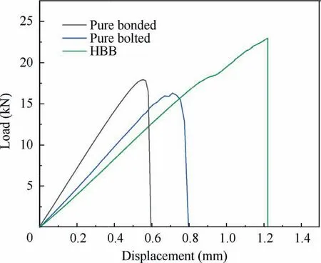
Fig. 11 Load–displacement curves of different joints.

Fig. 12 Effect of inter-bolt distance on tensile failure load of 20 mm wide hybrid joints.
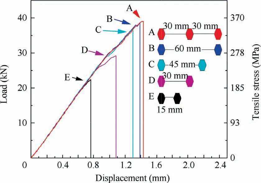
Fig. 13 Effect of inter-bolt distance on tensile failure load of 30 mm wide hybrid joints.
where P is the failure load of the hybrid joints;L is the overlap length; W is the joint width.
As mentioned in Section 2.1, the overlap length is equal to the outermost inter-bolt distance+30 mm.Since the areas of overlap are not the same for all the joints shown in Fig. 13,Fig. 14 gives an alternative graph showing the relationship between average shear stress and displacement for different inter-bolt distance. The overlap length L of the standard double-bolt hybrid joint is 60 mm,and the average shear stress under peak load is 16.20 MPa. The lap length of the standard three-bolt hybrid joint is 90 mm, and the average shear stress under peak load is 14.45 MPa.A double-nail hybrid joint with L=90 mm is added,and the average shear stress under peak load is about 14.32 MPa.The main observation from Fig.11 is that the average shear stress peak values of the lap lengths of 45 mm, 60 mm and 75 mm are almost the same, that is, the load transfer efficiency under these three-nail pitches is almost the same. However, the load transfer efficiency of the threenail and double-nail joints with L = 90 mm has been significantly reduced, indicating that the adhesive layer of the two is not fully functional and the joint can be simplified.
4.5. Influence of end distance on failure load of joints
In Section 4.4, the distance between the external bolt and the outer edge of the joint member is always maintained at 15 mm. Now take the 30 mm wide and 45-pitch double nail hybrid joint as the research object, and finite element model with bolt end distance of 10 mm, 15 mm, 20 mm, 25 mm,30 mm are adopted to analyze its tensile properties.
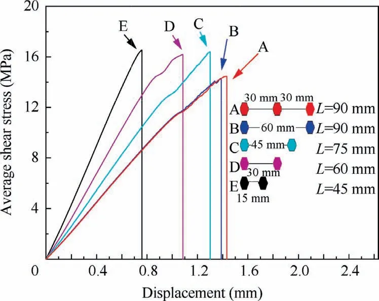
Fig. 14 Effect of bolt arrangement on average shear stress of 30 mm wide mixed joints.
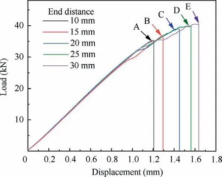
Fig. 15 Effect of bolt end distance on tensile failure load of 30 mm wide hybrid joints.
Comparing and analyzing the Groups A,B,C,D,and E in Fig. 15, it can be seen that as the end distance of bolts increases, the bearing capacity of the joint increases, but the increase amplitude gradually decreases.When the end distance exceeds 20 mm (group C), continuing to increase the end distance has no obvious effect on lifting the failure load of the joint, and the excessively large overlap area will increase the weight of the joint, and the adhesive layer is also prone to defects when the overlap area is too large. In practical engineering applications, the best end distance is 20 mm (Group C), which ensures that the joint has a good carrying capacity while taking into account economic costs.
5. Conclusions
Tensile tests of CFRP-titanium plate hybrid joints with different bolt numbers were carried out.At the same time,based on the cohesive zone model derived from the 3D Hashin failure criterion, the prediction model for the tensile strength of the composite laminate-titanium alloy plate multi-bolt hybrid joints was established. The numerical results are compared with the test results to verify the correctness of the model.Some conclusions derived from tests and numerical studies can be summarized as follows:
(1) The double-bolt hybrid joint can effectively improve the end warpage and low bearing capacity of the single-bolt hybrid joint. When the overlap width is 20 mm, the double-nail hybrid joint increases by 79.1% than the single-nail; when it is 30 mm, the failure load of the double-nail hybrid joint is 82.6% higher than that of the single nail.
(2) Under standard spacing,the three-nail hybrid joint has a higher bearing capacity than the double-nail joint, but under the same overlap length, the three-nail and the double-nail joint have almost the same bearing capacity,in other words, for multi-bolt hybrid joints, the joint strength is controlled by the adhesive and the outer bolts, while the inner bolts are redundant. The hybrid joint can be simplified by reducing the middle bolts.
(3) When the overlap width is 20 mm and 30 mm, the ultimate failure load of the double-nail hybrid joints gradually increases with the increase of the inter-bolt distance.With the inter-bolt distance increases from 15 mm to 45 mm, the joint failure load increases significantly. If the inter-bolt distance exceeds 45 mm, the increase in the failure load of the joint tends to be gentle, and the best inter-bolt distance is 45 mm. When the inter-bolt distance is 45 mm, the best end distance for a 30 mm wide double-nail joint is 20 mm.
The authors declare that they have no known competing financial interests or personal relationships that could have appeared to influence the work reported in this paper.
This study was co-supported by the National Natural Science Foundation of China (No. U1833116) and Key Scientific Research Project of Colleges and Universities in Henan Province, China (No. 20A460023).
 Chinese Journal of Aeronautics2022年3期
- Chinese Journal of Aeronautics的其它文章
- Flow response hysteresis of throat regulation process of a two-dimensional mixed-compression supersonic inlet
- A step parameters prediction model based on transfer process neural network for exhaust gas temperature estimation after washing aero-engines
- Recent progress in flexible supporting technology for aerospace thin-walled parts: A review
- Numerical investigation of dynamic stall suppression of rotor airfoil via improved co-flow jet
- Interaction formulae for buckling and failure of orthotropic plates under combined axial compression/tension and shear
- A refined design method for precoolers with consideration of multi-parameter variations based on low-dimensional analysis
