
Flow response hysteresis of throat regulation process of a two-dimensional mixed-compression supersonic inlet
2022-03-25 04:13:32YiJINShuSUNHuijunTANYueZHANGHexiaHUANG
Chinese Journal of Aeronautics 2022年3期
Yi JIN, Shu SUN, Huijun TAN, Yue ZHANG, Hexia HUANG
Jiangsu Province Key Laboratory of Aerospace Power System, College of Energy and Power Engineering, Nanjing University of Aeronautics and Astronautics, Nanjing 210016, China
KEYWORDS Hysteresis;Restart;Supersonic inlet;Throat regulation process;Unstart;Unsteady numerical simulation
Abstract The variable geometry supersonic inlet tends to decrease the throat area to reduce the Mach number upstream of the terminal shock, so as to reduce the flow loss. However, excessive Internal Contraction Ratio (ICR) exposes the inlet to a greater risk of unstart, which inevitably results in a process of increasing the throat area to aid the inlet restart. In the above throat regulation process,the inlet undergoes the start,unstart,and restart states in turn.In order to reveal the flow structure and mechanism of this process, a two-dimensional unsteady numerical simulation combined with a dynamic mesh technique were employed. The shock-on-lip Mach number of the studied inlet is 4.0 and the flight angle of attack is+6°. Analysis was focused on the state with a freestream Mach number of 3.0. The results clearly show that the flow response hysteresis appears,and restart is only realized when the throat area is obviously increased as compared to that of unstart due to the historical unstart flow structure.In addition,three typical flow fields were analyzed,and it is found that the separation ahead of the inlet was the key factor affecting the hysteresis.Finally,unstart and restart boundaries of the inlet were discussed,and the factors influencing its deviation from the typical boundaries of dual-solution area were analyzed. The newly predicted unstart and restart boundaries are much closer to the CFD results.
1. Introduction
For supersonic aircraft operating in the wide Mach number range, mixed-compression variable geometry supersonic inlets can balance the self-starting capability at low Mach numbers and performances at high Mach numbers. Among them, the two-dimensional variable geometry supersonic inlet has the advantages of various adjustment schemes, simple structure,and easy realization, which has considerable research significance and practical value.At present,the variable geometry scheme is mainly realized by rotatingor translatingthe cowl and regulating the throat.However,in actual flight missions,improper control strategies such as low operating Mach number,large angle of attack,high back pressure caused by the jetor improper fuel supply,and strong shock wave/boundary layer interactioncaused by large ICRcan easily lead to the inlet falling into the unstart state. Experimental and numerical studiesshown that ICR has dominant impact on the inlet performance. Large ICR improves the overall performance of the inlet, such as the compression capacity, total pressure recovery, and resistible back pressure ratio. Thus, the variable geometry supersonic inlet tends to increasing the ICR as far as possible to improve its performance. However, excessive ICR exposes the inlet to a greater risk of unstart. When the unstart state occurs, it is necessary to take immediate measures to aid the inlet restart. Therefore,the unstart/restart process is worth noting.
Many researchers have studied the supersonic inlet unstart/restart process by experiment or simulation, and the flow response hysteresis phenomenon is clearly observed.It is found that the hysteresis is mainly caused by the variation of the duct entrance Mach number, downstream back pressure, and ICR.First, the duct entrance Mach number is changed by controlling the acceleration processand adjusting the angle of attack,and the hysteresis loop for the key parameters is obtained. Second, Chang et al.altered the downstream back pressure by placing a flow plug at the duct exit, and the pressure signal variation curve of the moving plug process was measured, which was not completely symmetrical. Hong and Kimstudied the hysteresis of inlet buzz under the condition of backpressure change caused by the variation of downstream mass flow, and found that the inlet showed different buzz behaviors under the same mass flow. Some studiesalso reported the dual-solution behavior of the inlet flow field influenced by downstream back pressure. Chang et al.investigated the start/unstart mode transition process of a simplified scramjet, and the results show that due to the hysteresis effect it is necessary to significantly reduce the fuel supply in the combustor downstream of the inlet before the inlet is restarted. Third, Jiao et al.and Van Wie et al.studied the hysteresis phenomenon caused by the change of the cowl angle which altered the ICR, and pointed out that the shock wave/boundary layer interaction at the duct entrance is the key to the existence of the hysteresis. Yue et al.found that a larger cowl angle leads to larger separation and total pressure loss,and more obvious hysteresis phenomenon will occur in the inlet under the condition of a large ICR. Liu et al.pointed out in research on the change of ICR caused by rotating the cowl that the large-scale separation bubble at the duct entrance plays a critical role in the hysteresis of the restart process.The above results show that the hysteresis phenomenon in the unstart/restart process of supersonic inlets is widespread.However, most studies only mention this phenomenon, the key influencing factors and underlying mechanism require further study.
On the basis of this understanding of the above hysteresis phenomena, it can be found that the restart boundary of the inlet lags behind the unstart boundary, thus, the problem of the control boundaries of the unstart/restart process should also be considered. Based on the theoretical analysis of onedimensional inviscid flow, Kantrowitz and Donaldsonassumed that a normal shock stands at the duct entrance and the Mach number of the throat is one, thereby obtaining the Kantrowitz limit. Further, assuming the compression process of the inlet is isentropic, the isentropic limit is obtained.Combining the Kantrowitz limit with the isentropic limit,Timofeev et al.divided the working region of an inlet under different ICRs into start,dual-solution,and unstart regions.It is generally recognized that if the ICR is larger than the isentropic limit, the inlet will assume an unstart state, whereas if the ICR is smaller than the Kantrowitz limit, the inlet will assume a start or restart state. However, for the supersonic inlet,due to the complexity and diversity of the flow structures,the unstart and restart boundaries in actual working conditions typically deviate from the Kantrowitz and isentropic limits.If the effect of hysteresis phenomena on start boundaries is not correctly recognized, it may lead to mission failure.
In summary, the flow response hysteresis phenomenon is widespread in the unstart/restart process of the supersonic inlet,and it has a significant impact on the control of inlet start boundaries. Especially for variable geometry inlets, the hysteresis phenomenon is decisive for the design of the ICR control strategy.Therefore,it is necessary to understand the inner mechanism and perform a quantitative analysis to guide ICR control strategy design.Meanwhile,considering that hysteresis exists in the whole start/unstart/restart process, which is of strong historical dependence, unsteady numerical simulation combined with a dynamic mesh technique was adopted to investigate the unstart/restart process caused by throat regulation of the inlet.Moreover,in order to provide some guidance on estimating the unstart/restart boundaries, we attempt to reveal the flow structures in the unstart/restart process, and study the key influencing factors and underlying mechanisms of the hysteresis.
2. Model description
The research object is the low-speed duct of an external parallel turbined-based combined-cycle inlet from a two-dimensional variable geometry supersonic inlet.The corresponding variable geometry schematic diagram is shown in Fig.1,and the throat is regulated by a four-bar linkage.The shock-on-lip Mach number of the studied inlet is 4.0,the flight angle of attack is+6°,and the height of the duct entrance (H) is 74.9 mm. More detailed design parameters are shown in Table 1.The state with the freestream Mach number of (Ma) 3.0, the flight angle of attack of+4°is analyzed in detail.Moreover,the ICR is varied by rotating the second ramp at a rate of 18 (°) /s. Specifically, the ICR increases from 1.40 to 2.11 within 0–260 ms and decreases from 2.11 to 1.20 after 260 ms in the unsteady numerical simulation process,and the height of the throat varies from 35.5 to 62.5 mm.At the initial time, the inlet is in the start state at a small ICR, and the ICR is continuously increased to cause the inlet to transition into the unstart state,and then the ICR is decreased at the same rate until the inlet restarts.In this way,the unstart/restart process caused by regulating the throat of a two-dimensional variable geometry supersonic inlet can be simulated.
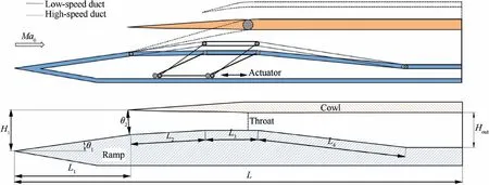
Fig. 1 Schematic diagram of inlet.

Table 1 Design parameters of inlet.
3. Numerical method and validation
3.1. Numerical method
Although it can be found in recent published papersthat there is three-dimensional effect in the supersonic inlet,the main flow structure of large aspect ratio rectangle inlet is highly two-dimensional. Thus, some studiesextracted the symmetrical plane of the rectangle inlet, and adopted two-dimensional Reynolds Averaged Navier-Stokes (RANS)equation to describe the main flow structure. The results shown that two-dimensional RANS simulation can accurately describe the wave system and flowfield of the inlet whether it is in the started or unstarted state.In general,high precision simulations such as Direct Numerical Simulation (DNS), Large-Eddy Simulation (LES), and Detached-Eddy Simulation(DES) are used for fundamental research of flow mechanism.However, for studies in complex inlet internal flows, the three-dimensional and two-dimensional RANS simulation are widely adopted.Due to the study in this paper is focused on throat regulation process of variable geometry supersonic inlet, the unsteady RANS simulation should be adopted. Moreover, considering the high cost of the unsteady three-dimensional RANS simulation, the unsteady twodimensional RANS simulation is finally chosen for current research.
In this paper, general-purpose CFD software was adopted to solve the two-dimensional compressible RANS equation,and the shear-stress transport k-ω turbulence model developed by Menterwas chosen to simulate the supersonic flow field structure.This model has good prediction ability for separated flow and flow under strong reverse pressure gradients,and has achieved good results in practical application.In the numerical simulation, the inviscid convection flux was split by the Roe scheme, the governing equation was discretized by the second-order upwind scheme, and the viscosity coefficient was solved by the Sutherland formula.For a freestream Mach number of 3.0, the static pressure is 8.06 kPa and the static temperature is 107.1 K. The computational meshes and boundary conditions are shown in Fig. 2. The mesh of the whole computational domain is structured with 150000 cells,and the refined mesh near the wall has a non-dimensional yless than 1 to meet the requirement of the turbulence model. Also, the dynamic mesh technique was adopted with unsteady numerical simulation to realize the throat regulation process, and the dual-time stepping implicit discretization method was employed to solve the unsteady flow field.Additionally, the Mach number at the duct exit and the mass flow through the exit were monitored in the simulation, and it was ensured that the residual convergence and monitored parameters were unchanged in each time-step.
The unsteady time-step (Δt) was selected according to the principle mentioned in Ref. 18 with a preliminarily value of 1×10s. For a freestream Mach number of 3.0, the characteristic velocity was defined as U=Mac (c is the speed of sound), and the non-dimensional time-step(Δt≡Δt ∙U/H) was 0.08, indicating that the selected time-step was sufficiently accurate. In order to further verify the accuracy of the time-step, four different time-steps(1×10s, 1×10s, 1×10s, and 1×10s) were chosen for unsteady numerical simulation validation.Considering the computational time–cost, the throat regulation process over the time range 0–200 ms was calculated, and the Mach number curve at the duct exit was selected for comparative analysis.Fig.3 presents the curves of Mach number at the duct exit(Ma)for different time-steps.It can be seen that there is a certain deviation in the curve when the time-steps are 1×10s and 1×10s, but the curves with time-steps of 1×10s and 1×10s basically coincide. Therefore, it is considered that a time-step of 1×10s is sufficient to meet the unsteady numerical simulation requirements at a relatively low cost.
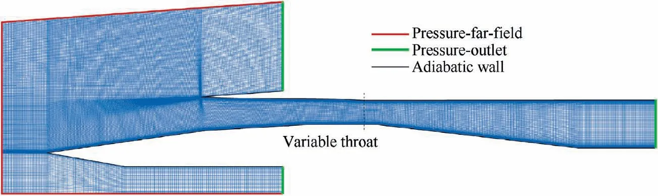
Fig. 2 Computational meshes and boundary conditions.
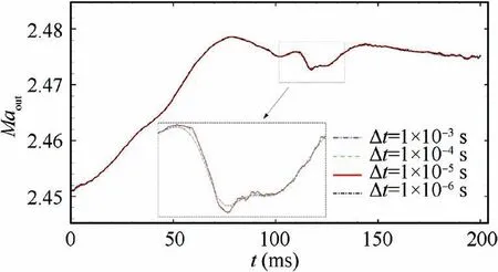
Fig. 3 Curves of Mach number at duct exit for different timesteps.
In addition, in order to further confirm whether the calculations obtained by unsteady RANS simulation are reasonable, three-dimensional (two-dimensional spanwise stretching) DES simulation with 2000000 grids is carried out.The typical state (fixed ICR=2.11) with serious unstarted separation is chosen to provide a comparison. Fig. 4 shows the comparison of the simulated results in the form of numerical schlieren by unsteady RANS and DES.As can be seen,the main flow structure of the unstarted separation captured by two methods is almost the same, which can confirm that the numerical method (unsteady RANS simulation) adopted in this paper is reasonable.

Fig. 4 Comparison of simulated results in form of numerical schlieren by unsteady RANS and DES.
3.2. Numerical validations
3.2.1. Supersonic flow structure of inlet
First, in order to check the accuracy of the numerical method used to describe the supersonic flow structure, the experimental resultof a rectangular hypersonic inlet was validated.The freestream Mach number, total temperature, and static pressure were 4.92, 580 K, and 0.7 MPa, respectively. The two-dimensional surface of the experimental inlet was extracted for numerical validation. Meanwhile, considering grid independence verification, the simulation results for a coarse grid (50000), fine grid (150000), and dense grid(300000) were compared with the experimental results, as shown in Fig. 5. The experimental and simulated static wall pressures are compared in Fig. 5(a) (p is the static pressure and subscript "0" denotes the freestream parameter). As can be seen, the obtained wall pressures are all in good agreement with the experimental results.The numerical and experimental schlieren images of the fine grid are compared in Fig.5(b),and the numerical results clearly and accurately show the supersonic flow structure of the inlet in the experiment.Considering the time–cost of subsequent unsteady numerical simulations,the fine grid with 150000 cells is chosen for subsequent simulations.

Fig. 5 Comparisons of experimental42 and numerical results of inlet.
3.2.2. Starting characteristics of supersonic inlets
Second, in order to check the accuracy of the numerical unsteady simulation combined with a dynamic mesh, the experimental resultsfor the starting characteristics of a supersonic inlet were validated. The test model is presented in Fig. 6, in which hrepresents the height of the cowl-lip and Lrepresents the length of the cowl. In the experiment,the cowl angle(θ)was continuously varied to obtain the limit contraction ratio of the unstart/restart state,and the hysteresis loop in the process of the unstart/restart was determined. The freestream conditions for the Mach number of 3.0, total pressure of 100 psi (1 psi=6895 Pa), total temperature of 300 K,and Reynolds number of 1.334×10/in (1 in=0.0254 m)were selected for validation. The parameters hand Lwere set to 0.7 in and 2.5 in,respectively.In the numerical unsteady simulation, the inlet was in the started state of a small cowl angle at the initial time,and the cowl angle was increased continuously by the dynamic mesh technique to cause the inlet to fall into the unstarted state, and then the cowl angle was decreased until the inlet restarted. Thus, the unstart/restart process in the experiment was numerically simulated. As before, the unsteady time-step was 1×10s.
The computational grid for the numerical validation is shown in Fig. 7. The number of grid cells is 150000, and the measurement points for the boundary layer characteristics are indicated in the figure.To simulate the rotation of the cowl in the experiment, the region around the cowl was mainly distributed with unstructured meshes, except for the region in close proximity to the cowl wall that was distributed with structured meshes to resolve the boundary layers.Comparisons of numerical and experimental boundary layer characteristic parameters and the hysteresis characteristic of the unstart/restart process are shown in Fig. 8, among which,δ, δ, θ and p/prepresent nominal thickness, displacement thickness, momentum thickness of the boundary layer, and the ratio of the pressure immediately below the cowl lip to the supply total pressure respectively. As can be seen in Fig. 8 (a), the numerical boundary layer characteristic parameters agree well with the experimental results,and the nominal boundary layer thickness at the cowl-lip station is 4.53 mm,which agrees well with the experimental result of 0.18 in(4.57 mm). As shown in Fig. 8 (b), the numerical hysteresis loop agrees well with the experimental results for the unstart/restart process, with simulated unstart and restart states appearing at cowl angles of 7.51°and 6.54°,respectively,and experimental states at 7.44°and 6.63°,respectively.Therefore, the unsteady numerical simulations supported by dynamic mesh technique are reasonable.
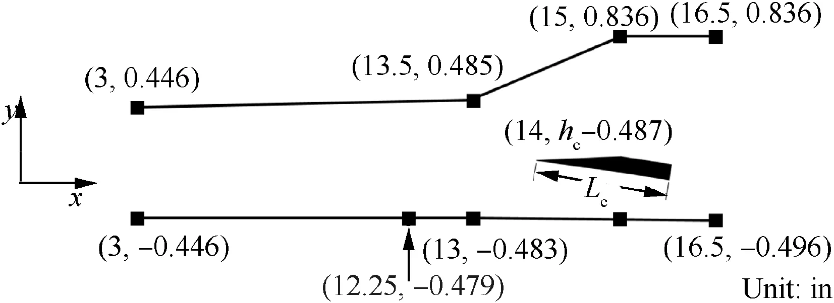
Fig. 6 Schematic diagram of test model of Van Wie 24.
4. Results and discussion
4.1. Initial started flow structure of inlet
The initial started flow structure of the inlet needs to be described. The ICR is set to 1.40 at the initial time. A numerical schlieren of the flow structure at the initial started state is shown in Fig. 9. It can be seen that the freestream passes through the external shock and reaches the duct entrance.After that a cowl-shock and an expansion wave are generated on the cowl and compression surface sides, respectively, and the reflection and intersection of the two waves in the inlet internal duct constitute a complex wave system. At this time,there are no large-scale separation bubbles in the internal duct,and a stable started supersonic flow structure is established.It should be noted that the intensity of the upstream cowl-shock does not change during the throat regulation process.
4.2. Unstart/restart process of inlet
This section presents the unstart/restart process of the inlet caused by regulating the throat. First of all, the started state is defined by Van Wieas follows: ‘‘the flow phenomena in the internal contraction section do not alter the capture characteristics of the inlet”, which is widely applied in recent studies. In the process of regulating the throat, when the separation shock moves across the leading edge of the cowl,extra spillage at cowl-side of the duct entrance caused by separation shock appears or disappears, which alters the capture characteristics of the inlet.Therefore,in the process of increasing the ICR, when the separation shock incidents on the leading edge of the cowl, we conclude that the inlet has begun to fall into an unstarted state, and the corresponding ICR is referred to the unstart ICR (denoted ICR). Further, in the process of decreasing the ICR, when the separation shock moves back and impinges on the leading edge of the cowl,we conclude that the inlet has realized the restarted state,and the corresponding ICR is referred to the restart ICR (denoted ICR).
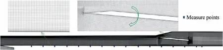
Fig. 7 Schematic diagram of computational grid.
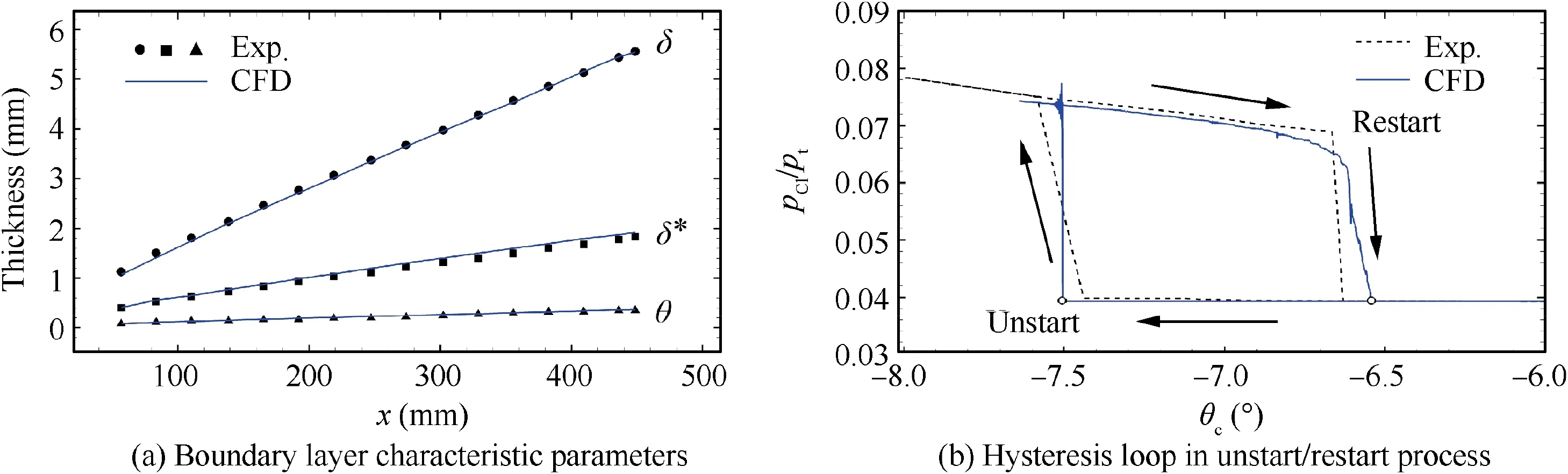
Fig. 8 Comparisons of experimental and numerical boundary layer characteristic parameters and hysteresis characteristic.
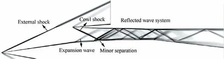
Fig. 9 Numerical schlieren of flow structure at initial started state.
Fig. 10 presents the variation curve of the mass flow ( ˙m)and the relevant hysteresis loop of the mass flow coefficient(φ)at the duct exit.As can be seen in Fig.10(a),the mass flow through the duct exit basically remains unchanged when the inlet is in the started state. However, when the ICR reaches 1.96, the separation shock incidents on the leading edge of the cowl, and the mass flow undergoes a sudden change indicating that the inlet has begun to fall into the unstarted state,thus, ICRis 1.96. Subsequently, the mass flow is slowly increased in the process of expanding the throat. When the ICR decreases to 1.37, the separation shock moves back and impinges on the leading edge of the cowl indicating that the inlet is restarted,thus,ICRis 1.37.It is noteworthy that since the cowl-shock is detached in the unstarted state,there is extra spillage cause by the detached cowl-shock at the duct entrance,therefore, the mass flow at the restart time is slightly smaller than at the started state. Moreover, a hysteresis loop of the mass flow coefficient in the throat regulation process is evident in Fig.10(b),especially that ICR(1.37)is much smaller than ICR(1.96).That is to say,when the ICR is larger than ICR,there are two solutions to the flow field.The detailed hysteresis phenomenon and the flow mechanism of the unstart/restart process will be investigated in the following parts.
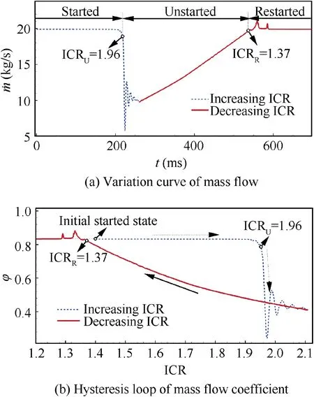
Fig. 10 Variation curve of mass flow and relevant hysteresis loop of mass flow coefficient at duct exit.
The Mach number contours of typical flow fields during the process of increasing the ICR are shown in Fig. 11, and the associated distribution of the ramp side static wall pressure is presented in Fig. 12. Meanwhile, streamlines and characteristic flow structures are marked in Fig. 11. As the process of increasing the ICR leads to a decrease in the height of the internal inlet duct, the number of reflections of the cowlshock in the internal duct increases, and the intensity of the reflected shocks are gradually enhanced, thereby increasing the compression strength of the entire inlet internal contraction section. Therefore, it can be seen from the distribution of the static wall pressure of the ramp side(Fig.12)that when the ICR increases,the overall pressure level of the internal contraction section is in an increasing state.When the ICR is 1.96,strong shock wave/boundary layer interactions cause largescale separation and complex wave structure in the internal contraction section.Thus,the wall pressure of the internal contraction section is also significantly higher than the started state. However. the pressure accumulated in the internal duct is already high enough, and it is difficult for the abovementioned flow structure to occur stably, so that once the ICR continues to increase,causing the pressure to rise,the separation is rapidly enlarged and pushed upstream. Subsequently, a large-scale unstarted flow field appears, as shown in Fig.11(d).Under this condition,there is an unstarted separation across the external compression ramp and the internal contraction section. The separation shock is located upstream of the cowl, leading to extra spillage at the duct entrance.Combined with Fig. 10(b), it can be seen that the mass flow coefficient of the inlet is 0.41, which is much smaller than the value of 0.83 in the started state with the same ICR.Additionally,the internal contraction section is mainly occupied by the unstarted separation,and the detached cowl-shock decelerates the flow to a subsonic flow. However, due to the influence of the expansion fan on the top of the separation,the flow accelerates to supersonic again,and a supersonic flow structure similar to the shock train is established in the internal contraction section.It is worth noting that in the unstarted state,due to the influence of extra spillage caused by the unstarted separation,and the wave system deviating from the design condition, the overall pressure level of the internal duct is lower than that for an ICR of 1.96.
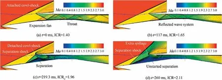
Fig. 11 Mach number contours of typical flow fields during process of increasing ICR.
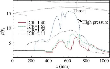
Fig. 12 Distribution of ramp side static wall pressure during process of increasing ICR.
The inlet ICR should be immediately decreased to make the inlet restart when a large-scale unstarted flow field occurs.The Mach number contours of typical flow fields during the process of decreasing the ICR are shown in Fig.13,and the associated distribution of ramp side static wall pressure is presented in Fig. 14. Meanwhile, streamlines to evaluate the flow capture characteristics are marked in Fig. 13. When the ICR is 1.96, the inlet is still in the large-scale unstarted flow field state, similar to that presented in Fig. 11(d). When the ICR decreases to 1.65, the unstarted separation moves downstream and its overall size is minimized. The reattachment compression wave of the unstarted separation results in a minor separation on the cowl side. When the ICR is 1.37,the inlet is restarted, because of the re-incidence of the separation shock on the leading edge of the cowl, along with the disappearance of the induced extra spillage. As the throat area is further enlarged, the compression of the internal contraction section decreases and the flow capacity of the throat increases, assisting downstream movement of the unstarted separation. When the ICR is 1.33, a small-scale separation bubble is located in the internal contraction section and its size has been significantly reduced. The separation shock is reflected by the wall of the cowl side and acts on itself, and the separation bubble leads to deviation of the wave system in the internal contraction section from the designed condition.When the ICR decreases to 1.31, the position of the reflected separation shock travels downstream, resulting in a trapezoid-like structure of the separation bubble. When the ICR further decreases to 1.29, the separation bubble is swallowed by the throat and finally disappears,thus,the inlet flow field returns to a stable started supersonic flow field similar to that of Fig. 11(a). Thus, the flow structure of the inlet is restored to the designed condition. Combined with the static wall pressure distribution on the ramp side shown in Fig. 14,it can be seen that the pressure of the entire internal duct is at a high level when the unstarted separation exists, because there is a complex shock train structure in the inlet internal contraction section. Once the unstarted separation has been swallowed by the internal duct,the shock train structure disappears causing the pressure level of the internal duct to drop significantly. Subsequently, as the ICR is further decreased, the flow structure of the inlet will return to the designed condition.It should be noted that although we conclude that the inlet is restarted when ICR is 1.33 and 1.31, there is small-scale separation bubble in the internal contraction section. Such flow structure deviates from the original designed condition shown in Fig. 9, resulting in the loss of aerodynamic performances,which cannot be ignored in actual flights.
4.3. Discussion of internal flow mechanism of hysteresis
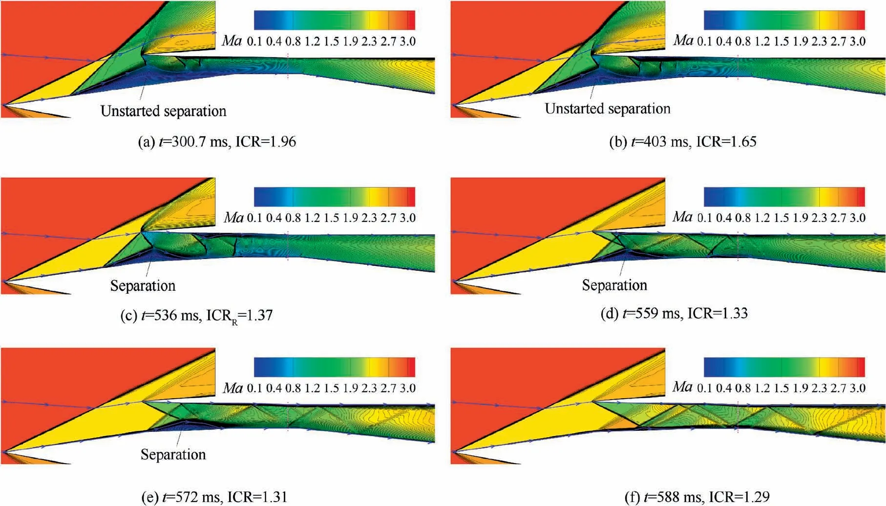
Fig. 13 Mach number contours of typical flow fields during process of decreasing ICR.
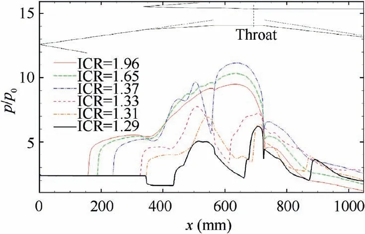
Fig. 14 Distribution of ramp side static wall pressure during process of decreasing ICR.
As mentioned above, there is obvious flow response hysteresis in the mass flow coefficient of the inlet (Fig. 10(b)), the flow mechanism of this hysteresis will be analyzed next. Fig. 15 shows comparisons of the flow field characteristics of the inlet at the same ICR for several ICR values during the throat regulation process. Among which, Fig. 15(a) shows comparisons of the static pressure distribution contour of the flow field,with the location of the sonic line and geometric throat, and Fig.15(b)shows comparisons of the key parameters at the geometric throat, where φ; p/p, and σrepresent the mass flow coefficient, dimensionless pressure increase, and total pressure recovery at the station of the geometric throat, respectively.First of all, it can be seen from the sonic line that when the inlet is in the started state, its flow capacity is limited by the geometric throat. But when the inlet is in the unstarted state,the flow structure formed by the separation at the duct entrance increases the total pressure loss, and the downstream flow is choked, thus the generation of an aerodynamic throat replaces the geometric throat limiting the maximum flow passing through the inlet internal duct. Second, the pressure levels of the geometric throat and the internal duct in the unstarted state are higher than that in the started state. This is because the flow structure caused by the separation bubble at the duct entrance deviates from the design condition, resulting in a more complicated shock wave/boundary layer interaction and a high reverse pressure gradient in the internal duct, that is not conducive to aid the inlet to restart. In addition,although for an ICR less than 1.37 (the restart ICR), the flow at the duct entrance has been completely captured, the total pressure recovery of the throat under these conditions is still smaller than the value of the started state. This is disadvantageous to the normal and stable operation of the inlet and engine.According to the above analysis,the separation bubble at the duct entrance not only reduces the flow capacity of the inlet, but also increases the reverse pressure gradient of the internal contraction section and aggravates the severe shock wave/boundary layer interaction, impeding inlet restart.Therefore, the formation of a separation bubble at the duct entrance is a key factor influencing the hysteresis phenomenon of the inlet unstart/restart process.

Fig. 15 Comparisons of flow field characteristics of inlet under same ICR during throat regulation process.
Furthermore, the inlet can be classified into three typical flow fields according to the formation of the separation bubble at the duct entrance during the throat regulation process, as shown in Fig. 16. They are the unstarted flow field dominated by a large-scale separation bubble (denoted Flow field-A), the flow field dominated by a small-scale separation bubble in the internal contraction section (denoted Flow field-B), and the flow field in the design condition(denoted Flow field-C).First,Flow field-A is characterized as follows.The separation bubble is large-scale, across the external ramp and the internal contraction section, and the separation shock is located upstream of the cowl leading to extra spillage at the duct entrance.Fig.17 shows variation curves of the position of the separation point and the spillage rate(Ψ)during the process of increasing the throat area. As is evident, when the inlet is in the state of Flow field-A, as the ICR decreases, the separation bubble moves downstream smoothly, and the spillage decreases until it disappears.This is because according to the extent of downstream blockage, the separation bubble can adjust its scale automatically, thereby adjusting the spillage to achieve dynamic balance automatically. However, it can be seen from the flow field of Fig. 16(a) that there is a first aerodynamic throat at the top of the separation bubble, and the mass flow blockage induced by this throat restricts the separation bubble from continuing to move downstream. Moreover, a second aerodynamic throat exists slightly upstream of the geometric throat, and the high pressure associated with the generated upstream shock train brings about additional total pressure loss, while continuous expansion occurs downstream of the second aerodynamic throat.From the perspective of flow continuity, the completely captured flow passes through the separation bubble leading to spillage, and then suffers a total pressure loss when passing through the cowl-shock and the downstream shocks, and reaches the speed of sound again at the second aerodynamic throat.Therefore,the second aerodynamic throat is the throat that actually limits realization of the inlet restart. Second, Flow field-B is characterized as follows.The separation bubble is located in the internal contraction section, and the mass flow at the duct entrance has been completely captured.Compared with the unstarted flow field dominated by the large-scale separation bubble, the separation bubble cannot adjust the captured mass flow by changing its scale.It should be noted that although there is an aerodynamic throat at the top of the separation bubble, the main stream is not choked. In addition, in the limited internal duct, the reflected separation shock acts on the separation itself and the induced high pressure can maintain the separation bubble.That is to say,the cowl-shock,separation shock,reflected separation shock, and separation bubble form a self-sustained stable flow structure. However, as seen in Fig. 17, as the ICR decreases, the velocity of the separation bubble moving downstream becomes much higher than that of the previous stage. This is because the internal duct of the inlet is not obstructed,and the downstream reverse pressure of the separation is greatly relieved. Moreover, with the separation moving downstream,the reflected separation shock is gradually decoupled from the separation bubble, further speeding up downstream movement of the separation bubble. Third, Flow field-C is the same as the initial started flow field in Fig. 9 with a steady supersonic flow field in the inlet internal duct.Through the above analysis, it can be concluded that the process of the separation bubble being swallowed by the internal duct depends on the historical path,thus,the influence of the historical flow field caused by the unstarted separation bubble directly leads to the hysteresis in the throat regulation process.
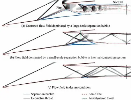
Fig. 16 Typical flow fields in throat regulation process.
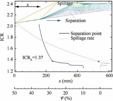
Fig. 17 Variation curves of position of separation point and spillage rate during process of increasing throat area.
4.4. Discussion of unstart/restart boundaries
In theory, the aera between the Kantrowitz limitand the isentropic limit can be considered to be the start/unstart dual-solution area.In the dual-solution area, there are two kinds of flow fields, namely the started and unstarted flow fields according to the different historical flow fields of the inlet.The existence of the dual-solution area is also the fundamental physical reason for the hysteresis phenomenon in the switching process of start, unstart, and restart. However, the complex flow structure and total pressure loss of the duct entrance are not considered in the analysis of the boundary of the dual-solution area. Therefore, the flow structure of the duct entrance is extracted and the relevant flow characteristics are analyzed, also, the influence of the total pressure loss is considered. Further, since the variable geometry supersonic inlet operates over a wide range of Mach numbers, in order to increase the generality, the operating conditions for freestream Mach numbers of 2.5, 3.5 and 4.0 were added for simulation, and the results are presented in Table 2 (in which α and Mais flight angle of attack and Mach number at the duct entrance respectively). At the relevant duct entrance Mach number, the positions of the unstart and restart boundaries in the dual-solution area are shown in Fig. 18. It is obvious that the unstart and restart boundaries deviate from the theoretical boundary of the dual-solution area. Specifically, the unstart ICR is smaller than that of the isentropic limit, while the restart ICR has no definite relationship with that of the Kantrowitz limit.
In order to study the reason why the unstart and restart boundaries deviate from the boundaries of the dual-solution area, Fig. 19 presents comparisons of the typical flow structures between the boundaries of the dual-solution area and the unstart/restart process. Taking the inlet internal contraction section as the control volume for analysis, assuming thatthe compression process of the freestream is isentropic, and that the flow decelerates to the speed of sound at the throat(Fig. 19 (a)), the isentropic limit can be obtained as follows:
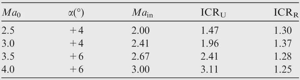
Table 2 Calculation results for different freestream Mach numbers.
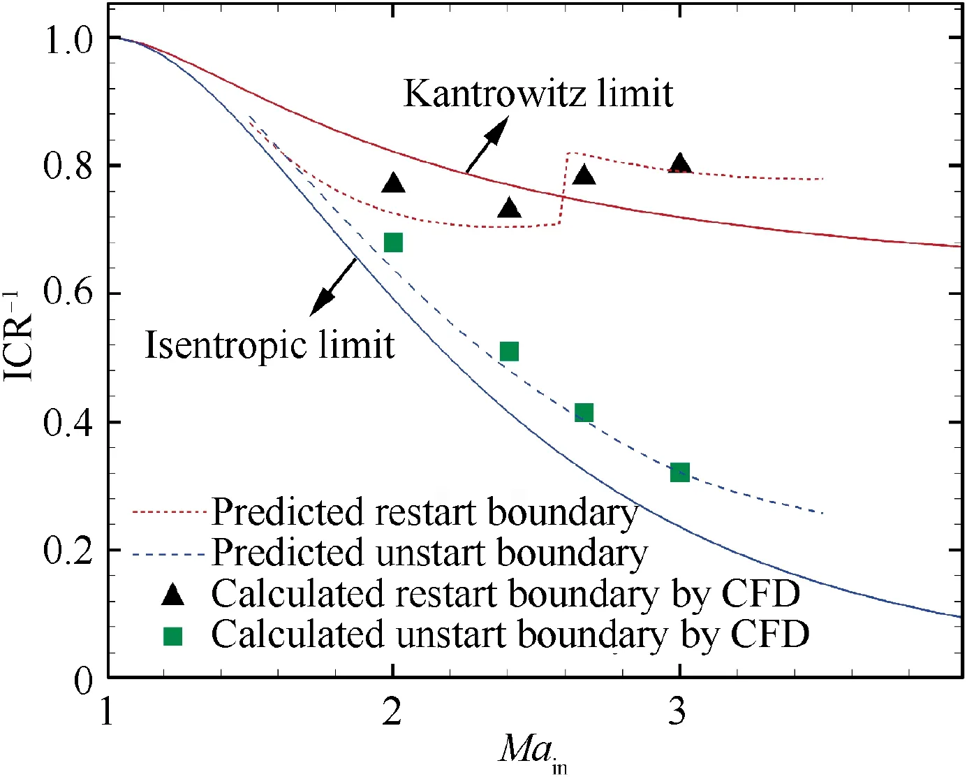
Fig. 18 Unstart and restart boundaries of dual-solution area.
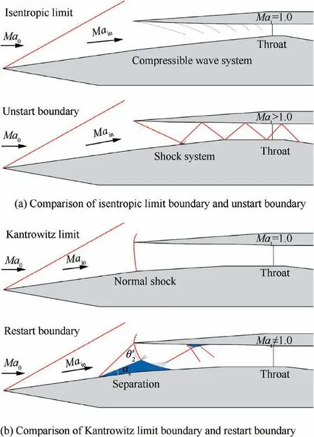
Fig. 19 Comparisons of typical flow structures between boundaries of dual-solution area and unstart/restart process.
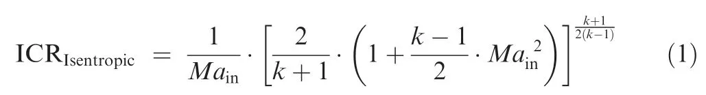
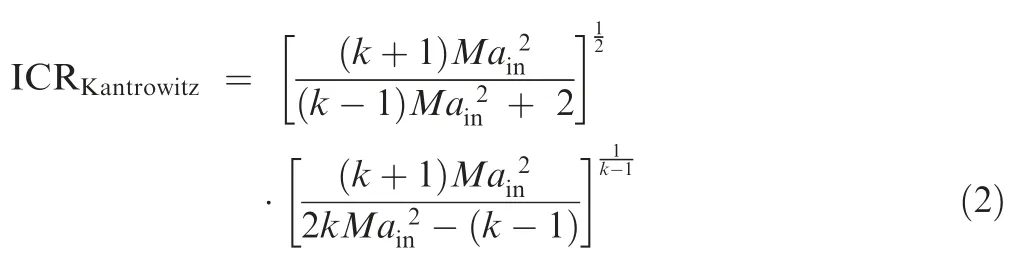
where k is specific heat ratio with a value of 1.40. Assuming that the flow to be one-dimensional and quasi-steady,a normal shock stands at the duct entrance, and the flow decelerates to the speed of sound at the throat (Fig. 19 (b)), and the total pressure loss is only caused by the normal shock,the Kantrowitz limitcan be obtained as follows:
Initially,the reason that why the unstart boundary deviates from the isentropic limit is analyzed. It should be noted that Marepresents throat Mach number in Fig. 19. And it can be seen from Fig. 19(a) that in the practical working process of the supersonic inlet, the cowl-shock undergoes multiple reflections in the internal contraction section to form a complex shock system that causes a non-negligible total pressure loss compared with the isentropic compression process, thus the actual unstart ICR is smaller than that of the isentropic limit. If the effect of the actual total pressure loss in the internal contraction section is considered, based on the knowable isentropic limit and the theoretical inviscid wave system, the total pressure loss from the duct entrance to the throat can be estimated, and the predicted unstart boundary can be obtained. As a supplement, Fig. 20 gives the detailed process of predicting the unstart boundary in the form of the flow chart (in which superscript ‘‘*” represents the stagnation parameter, and subscripts ‘‘in” and ‘‘t” represent parameters at duct entrance and throat respectively). As a result, it can be seen from the blue dashed line in Fig. 18 that the predicted unstart boundary is relatively close to the calculated unstart boundary by CFD in this paper. That is to say, as long as the total pressure loss in the inlet internal contraction section is accurately predicted, an unstart boundary predicted on the basis of the isentropic limit that is closer to the CFD results can be obtained.
Next, the reason that why the restart boundary deviates from the Kantrowitz limit is analyzed. It can be seen from Fig. 19(b) that there are significant differences between the flow structure of the inlet restart boundary and the flow structure of the Kantrowitz limit.More specifically,Fig.21 presents the Mach number contours of the flow field corresponding to the restart boundary under different freestream Mach numbers, in which the sonic line, geometric and aerodynamic throats are highlighted. There is a combination of separation shock and cowl-shock at the duct entrance, which is different from the assumption of the Kantrowitz limit that a normal shock stands at the duct entrance.However,there is a complex wave system induced by the duct entrance separation bubble in the internal contraction section, which leads to the extra total pressure loss caused by the shock.In addition,under different freestream Mach numbers,the wave system in the inlet internal contraction section corresponding to the restart boundary is also distinguished. When the cowl-shock is detached, the flow field is similar to Flow field-A analyzed in Section 4.3. There are two aerodynamic throats in the internal contraction section, and the flow is chocked near the geometric throat, so the mainstream Mach number is almost sonic.However,when the cowl-shock is attached, there is only one aerodynamic throat in the internal contraction section, and the mainstream Mach number of the geometric throat is supersonic. Based on the above analysis, the reason that the restart boundary deviates from the Kantrowitz limit can be explained.It is noteworthy that the state of the cowl-shock (attached or detached)leads to the sudden change of the restart boundary in Fig. 18. Even for some freestream Mach numbers, the calculated restart ICR by CFD is smaller than that of the Kantrowitz limit, which is also discovered in Refs.. Therefore,the Kantrowitz limit is not an absolutely conservative method to predict the restart boundary of a supersonic inlet.
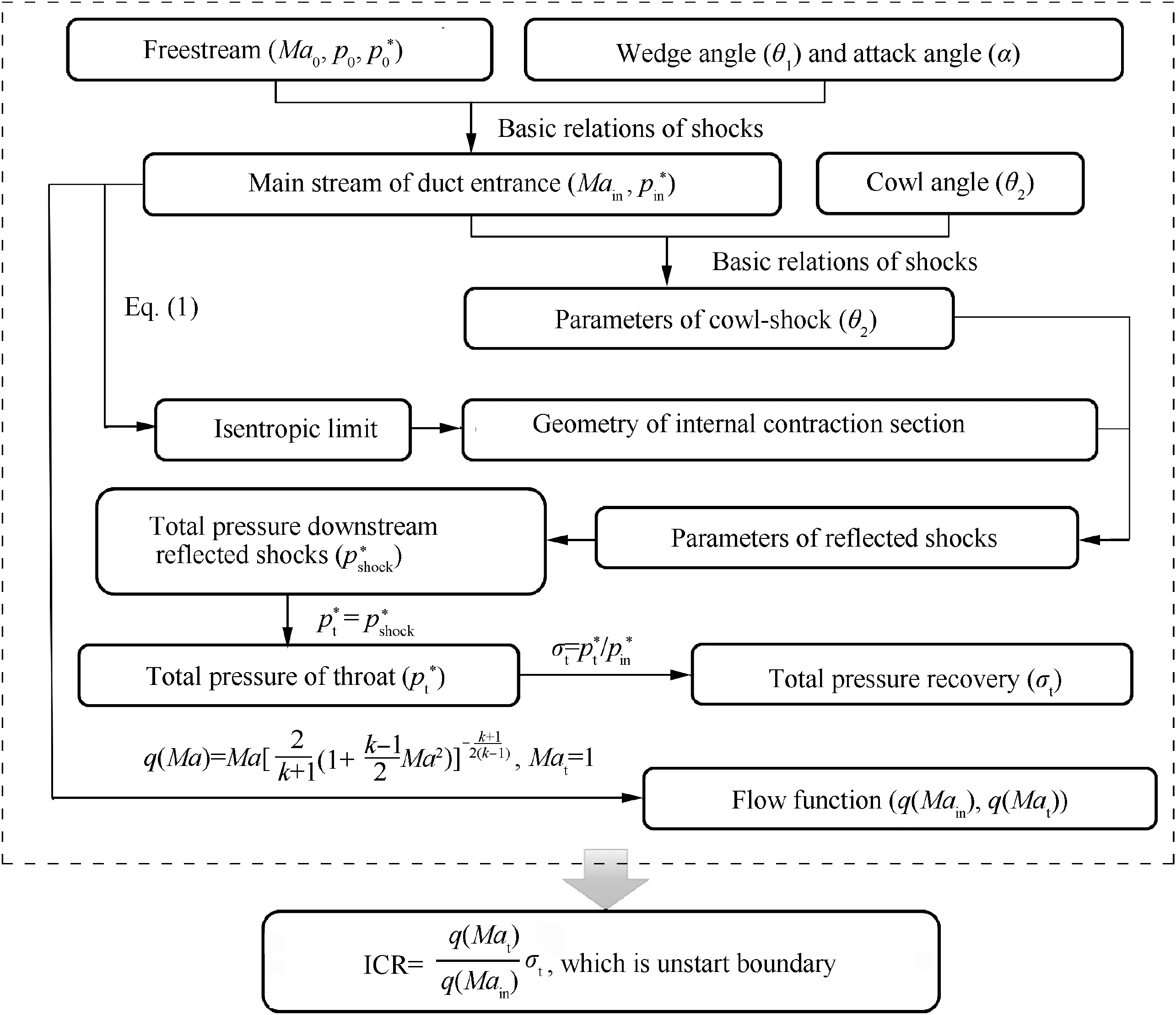
Fig. 20 Flow chart of predicting unstart boundary.
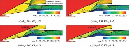
Fig. 21 Mach number contours of flow field corresponding to restart boundary under different freestream Mach numbers.
According to the above discussions, in order to obtain a more accurate restart boundary, the total pressure loss caused by the complex wave system in the internal contraction section and the influence of throat Mach number should be considered at the same time. In other words, it is necessary to modify the mass flow function (denoted q(Ma)) and the total pressure recovery (denoted σ) at the throat station in Eq. (3).
In view of the fact that the detached or attached state of the cowl-shock determines different flow structures of the restart boundaries, Fig. 22 extracts two diagrams of typical flow structures. For better understanding of the following analyses, Fig. 23 gives the detailed process of predicting the restart boundary in the form of the flow chart. Initially, it is essential to determine the detached or attached state of cowl-shock at different duct entrance Mach numbers for classification purposes. On the basis of Eq. (4) proposed by Zukoski, which is applicable to turbulent boundary layer induced separation bubbles at high Reynolds numbers, the plateau pressure of the duct entrance separation bubble (p)can be calculated.
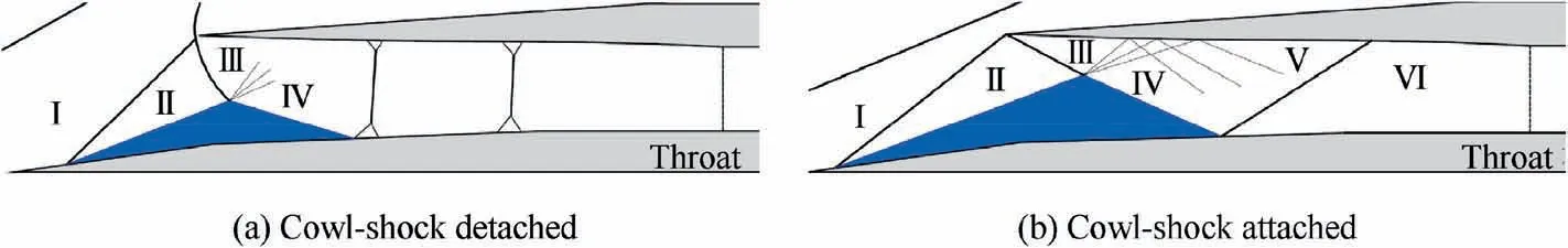
Fig. 22 Diagrams of typical flow structures of restart boundaries.

Fig. 23 Flow chart of predicting restart boundary.

First, a diagram of a typical flow structure of the restart boundary for detached cowl-shock is presented in Fig. 22(a).Among the regions shown, region I corresponds to the inlet mainstream; region II corresponds to the mainstream directly after the separation shock;region III corresponds to the mainstream directly after the cowl-shock; and region IV corresponds to the mainstream accelerated by the expansion fan on top of the separation bubble. Additionally, the shock train exists downstream of region IV,leading to the blockage of the mainstream near the throat, and hence to regarding the mainstream as sonic (Ma= 1). The aerodynamic wedge angle,separation shock angle,and state of the cowl-shock were determined above,thus the mainstream static parameters of regions I, II, and III can be further obtained. From region III to IV,the total pressure of the mainstream remains unchanged passing through the expansion fan.Meanwhile,there is an isobaric zone in the separation bubble,thus, the static pressure in regions II and IV can be assumed to be the same.Furthermore,on the condition that the static pressure and total pressure are knowable, the mainstream Mach number in region IV can be acquired. Thus, according to the mainstream Mach number and basic relation of the normal shock in region IV, the total pressure loss caused by a single normal shock can be obtained.The studyindicated that the total pressure loss caused by thehead wave of a normal shock is about 70%of the whole shock train. Thus, the total pressure loss of the shock train in the internal contraction section is further acquired. Thus far, the total pressure recovery coefficient (denoted σ) of the mainstream from the duct entrance to the throat can be obtained.And the total pressure loss is caused by the separation shock,the cowl-shock, and the shock train respectively, and the predicted ICR is further calculated according to Eq.(3).Second,a diagram of a typical flow structure of the restart boundary for attached cowl-shock is presented in Fig. 22(b). It is easy to acquire the mainstream static parameters corresponding to regions I, II, III, and IV when the duct entrance parameters are known. However, different from the state when the cowlshock is detached, the top of the separation bubble is closer to the cowl side, and the reflection of the expansion fan on the cowl wall has a significant impact on the upstream mainstream of the reattachment shock. Region V corresponds to the mainstream accelerated by the reflected expansion fan.Based on the fact that when the expansion wave reflects on the solid wall,it accelerates again through the same expansion angle,it is necessary to know the expansion angle at the top of the separation bubble. The Mach numbers of regions III and IV have been acquired, so the expansion angle at the top of the separation bubble can be calculated by the Prandtl-Meyer expansion wave formula.Furthermore, the mainstream static parameters in region V can be obtained. Moreover, region VI corresponds to the mainstream through the reattachment shock of the separation bubble. In order to acquire the mainstream parameters in region VI,it is necessary to obtain the compression angle of the reattachment shock.Yet the ICR is unknown,even if the aerodynamic profile angle of the reattachment part of the separation bubble is calculated above, the compression angle of the reattachment shock still cannot be obtained. To solve this problem, the supposed ICR is applied for the calculation of the compression angle of the reattachment shock, thus the static mainstream parameters in region VI can be acquired. Moreover, due to the geometric surfaces of region VI being approximately parallel, the total pressure loss of the mainstream in this section is quite small, therefore, it can be considered that the static mainstream parameters at the throat station are the same as those in region VI. Thus far, the throat Mach number (denoted Ma) and the σof the mainstream from the duct entrance to the throat can be obtained. And the total pressure loss is mainly caused by the separation shock, the cowl-shock, and the reattachment shock, respectively, and the predicted ICR is further calculated according to Eq. (3). Subsequently, the accurate ICR of the restart boundary dominated by the attached cowl-shock can be obtained by iterating the supposed and predicted ICR.According to the analysis of the above two cases, the predicted restart boundary is obtained, as indicated by the red dashed line of Fig. 18, which shows that the calculated restart boundary by CFD is well predicted by the proposed method.
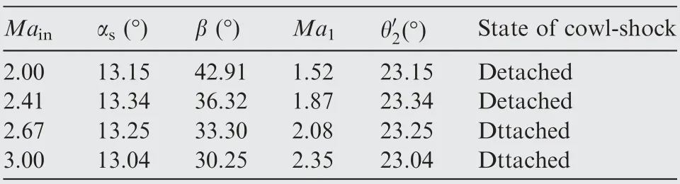
Table 3 Flow parameters at different duct entrance Mach numbers of restart boundaries.
5. Conclusions
In order to reveal the flow structure and mechanism, and to provide some guidance on estimating the unstart and restart boundaries, a two-dimensional unsteady numerical simulation combined with a dynamic mesh technique was employed to examine the throat regulation process of a two-dimensional mixed-compression supersonic inlet. The shock-on-lip Mach number of the studied inlet was 4.0 and the flight angle of attack was+6°. Simulations were performed for states with incoming Mach numbers of 2.5, 3.0,3.5, and 4.0, with a focus on analyzing the state of freestream Mach number of 3.0.Based on the analysis and discussions of the CFD results,the following conclusions are drawn.
(1) An obvious flow response hysteresis loop occurs in the throat regulation process, especially that the restart ICR is far smaller than the unstart ICR. In the process of increasing the ICR, the cowl-shock induced a more complex wave system in the inlet internal contraction section, and the strong shock wave/boundary layer interactions caused large-scale separation and complex wave structure in the internal contraction section.Subsequently, the separation rapidly enlarged and moved upstream to form a large-scale unstarted flow field. In the process of decreasing the ICR, the separation at the duct entrance moved downstream gradually along with the reduction of its scale, and is finally swallowed through the throat.
(2) The separation bubble at the duct entrance is the key factor influencing the hysteresis phenomenon in the inlet unstart/restart process. It not only reduces the captured airflow of the inlet, but also increases the reverse pressure gradient of the internal contraction section, resulting in a more severe shock wave/boundary layer interaction,and causing the inlet difficult to restart.Furthermore, according to the form of the separation bubble at the duct entrance, the inlet can be classified into three typical flow fields of the unstarted flow field dominated by the large-scale separation bubble,the flow field dominated by the small-scale separation bubble in the internal contraction section, and the flow field in the design condition. Especially, in the situation of the unstarted flow field dominated by the large-scale separation bubble, according to the extent of downstream obstruction, the separation bubble can adjust its scale automatically, thereby adjusting the spillage to achieve dynamic balance automatically.
(3) It is obvious that the unstart and restart boundaries deviate from the theoretical boundary of the dualsolution area.The reason that why the unstart boundary deviates from the isentropic limit is the existence of the non-negligible total pressure loss in the inlet internal contraction section. The reason that why the restart boundary deviates from the Kantrowitz limit can also be explained as follows. The wave system at the duct entrance is different from that assumed by the Kantrowitz limit, and there is extra total pressure loss caused by the complex wave system in the inlet internal contraction section. In addition, the influence of the throat Mach number must be taken into consideration. Moreover,the detached or attached state of the cowl-shock is also a key factor affecting the restart boundary. Taking the above factors into account, the boundaries of the dualsolution area can be predicted according to the extracted typical flow structure, and the predicted unstart and restart boundaries are much closer to the CFD results.It should be noted that considering the possibility that the restart ICR is smaller than that of the Kantrowitz limit, the Kantrowitz limit cannot always be used as a conservative method to predict the restart boundary of a supersonic inlet.
The authors declare that they have no known competing financial interests or personal relationships that could have appeared to influence the work reported in this paper.
This study was co-supported by the National Natural Science Foundation of China (Nos. U20A2070, 12025202, 11772156,51806102, and 51906104). The authors appreciate valuable comments of the reviewers and editorial committee.
 Chinese Journal of Aeronautics2022年3期
- Chinese Journal of Aeronautics的其它文章
- Film cooling performance and flow structure of single-hole and double-holes with swirling jet
- Lock-in phenomenon of tip clearance flow and its influence on aerodynamic damping under specified vibration on an axial transonic compressor rotor
- Solid rocket propulsion technology for de-orbiting spacecraft
- Bioinspired polarized light compass in moonlit sky for heading determination based on probability density estimation
- Effects of sweep angles on turbulent separation behaviors induced by blunt fin
- Design and analysis of a novel hinged boom based on cable drive