Film cooling performance and flow structure of single-hole and double-holes with swirling jet
Rui ZHU, Simon TERRENCE, Shulei LI, Gongnan XIE
a School of Mechanical Engineering, Northwestern Polytechnical University, Xi’an 710072, China
b Research & Development Institute of Northwestern Polytechnical University in Shenzhen, Shenzhen 518057, China
c Department of Mechanical Engineering, University of Minnesota, Minneapolis, MN 55455, USA
d School of Marine Science and Technology, Northwestern Polytechnical University, Xi’an 710072, China
KEYWORDS Combined-hole;Film cooling;Interactions of vortices;Jet-in-cross-flow;Swirling flow
Abstract This paper presents the results of a numerical study of the effects of swirling flow in coolant jets on film cooling performance.Some combined-hole designs with swirling coolant flow entering the delivery hole are proposed and analyzed. Adiabatic film cooling effectiveness values for cases with various blowing ratios are compared. Detailed flow structures and underlying mechanisms are discussed. The results show that film cooling effectiveness is improved with jet swirl at high blowing ratios, and that swirl strength has significant influence on film cooling performance.Combined-hole designs can further improve film cooling performance using swirling jets due to mixing of coolant flows and interaction of vortices.The largest improvements of area-averaged film cooling effectiveness for a single-hole swirl case and a combined-hole swirl case over corresponding non-swirling case results are 157% and 173%, respectively.
1. Introduction
The inlet temperatures of modern gas turbines are continuously being increased while striving for higher efficiency.Values now exceed the material limit temperature, making advanced cooling methods indispensable. Film cooling was first applied to engine cooling in the 1970s, and has become one of the most efficient and widely used cooling schemes in turbines. Film cooling uses coolant air from internal cooling channels ejected though passage surfaces to form coolant films over the surfaces to be cooled, protecting them from the hot mainstream flow.
Many investigations have been conducted over the past decades toward understanding film cooling flow and heat transfer mechanisms and effects of geometry and flow parameters, aiming for improvements. Relevant works are summarized by Bogard and Tholein 2006. The main factors that affect film cooling performance in gas turbines include:coolant/mainstream conditions, like cooling-to-mainstream mass flux ratio,density ratio,turbulence intensity of the mainstream;hole geometry, like hole L/D ratio,injection angle,and hole shape;hole configurations and airfoil geometry, like spacing between adjacent holes and spacing between different rows,hole locations on airfoils and surface curvature.Zhang et al.reported recent improvements of film cooling in 2020, including passive strategies(shaped holes,ramps,trenches,and slots)and active strategies(pulsation modulating device and plasma actuator).
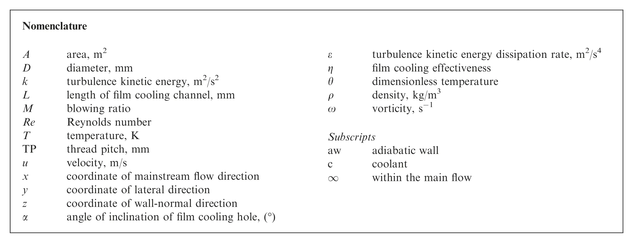
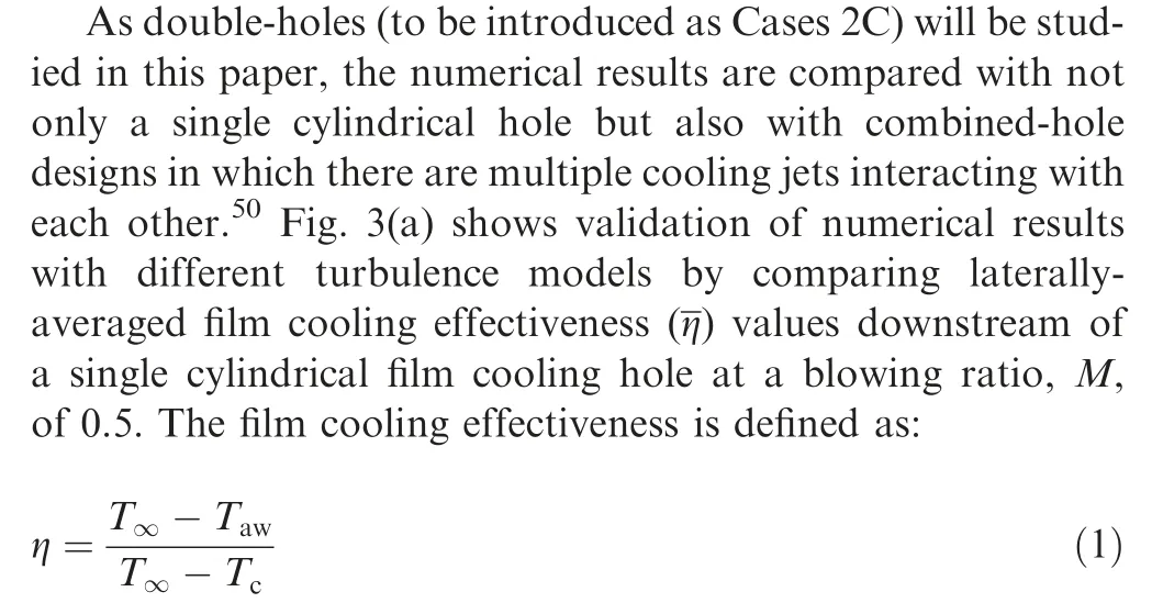
Nomenclature Aarea, m2 Ddiameter, mm kturbulence kinetic energy, m2/s2 Llength of film cooling channel, mm Mblowing ratio ReReynolds number Ttemperature, K TPthread pitch, mm uvelocity, m/s xcoordinate of mainstream flow direction ycoordinate of lateral direction zcoordinate of wall-normal direction αangle of inclination of film cooling hole, (°)εturbulence kinetic energy dissipation rate, m2/s4 ηfilm cooling effectiveness θdimensionless temperature ρdensity, kg/m3 ωvorticity, s-1 Subscripts awadiabatic wall ccoolant∞within the main flow
The canonical flow structure corresponding to film cooling is called the ‘‘Jet-In-Cross-Flow” (JICF). Fric and Roshkoproposed a vortical structure for JICF that includes four parts:horseshoe vortices; jet shear-layer vortices; counter-rotating vortex pairs and wake vortices. The Counter-Rotating Vortex Pair (CRVP), also referred to as the ‘‘kidney vortex pair,” is the main feature in the JICF flow field. The CRVP does harm to film cooling effectiveness as it brings hot mainstream flow air toward the surface, enhances mixing between the mainstream and coolant, and tends to lift the coolant film off the surface.With increasing blowing ratios, the CRVP strengthens, which is the main reason that film cooling effectiveness with cylindrical holes usually drops precipitously with blowing ratios larger than 1.0. The formation of kidney vortex pairs is mainly attributed to two effects. One is the interaction of the jet with the crossflow.Small vortices begin to take form in the near field and grow in the downstream field. The other effect is that kidney vortices have their origin somewhere in the coolant delivery pipe boundary layer.
Many designs have been proposed to enhance film cooling effectiveness by weakening the kidney vortex pair.One method is to design shaped holes.Another is to use ramps,trenches or tabs near the hole exits to change the interaction between coolant jets and the mainstream.However, these two methods increase machining difficulty or decrease mechanical and aerodynamic properties of the airfoils. Therefore, a new way to weaken the CRVP by combining several cylindrical holes to create an anti-kidney vortex structure was recently proposed. Ely and Jubranproposed a method to create an anti-kidney vortex structure by adding secondary holes called ‘‘sister holes” near the primary hole. Heidmann and Ekkaddesigned a film cooling hole structure that is a main cylindrical hole with two smaller, branched side holes, named the ‘‘anti-vortex hole.” Kusterer et al.designed ‘‘double-jet holes” using two compound-angle cylindrical holes. These designs can enhance film cooling effectiveness because the combined-hole design will create an‘‘anti-kidney vortex structure” in which the harmful CRVP is weakened by interaction of vortices.
Swirling flows are applied in many industrial settings, like heat exchangers with enhanced heat transfer characteristics,and are also applied in different regions of gas turbines. In the combustor, swirl is used to enhance fuel–air mixing, stabilize combustion and hold the flame.In gas turbine cooling systems, swirling flows can improve cooling efficiency in internal cooling channelsand in jet impingement coolingsituations. Film cooling performance in modern gas turbines can be highly influenced by swirl. The main flow at the combustor-turbine interface is nonuniform and consists of swirling flows due to the swirl generators used for combustion. This swirl has negative effects on the aerodynamics and heat transfer features of the turbine.Existing works about the effects of swirl on film cooling are mainly focused on swirling flows in the mainstream. Few consider the effects of swirl in the coolant flow. Takeishi et al.experimentally studied the effects of swirl of coolant on film cooling performance using cylindrical and fan-shaped holes. The coolant was ejected through film cooling holes after impingement cooling that introduced swirl. The results show that film cooling performance can be improved under certain swirling conditions.Yang et al.numerically analyzed the influence of swirling motion in coolant in cylindrical holes, clover shaped holes,and compound-angle cylindrical holes. It was found that both film cooling effectiveness values and heat transfer coefficients can be increased by introducing swirl to coolant flow.
Presently, new turbine cooling concepts have been proposed, like double-wall airfoils with thin outer-walls and film cooling holes with short L/D ratios. As a result, the coolant flow cannot be fully developed within the short holes and swirling flows caused by cross-flow interactions,impingement cooling,and internal channel geometries like pin-fins or ribs inside the channels,affect film cooling performance. As a result, studying the performance of film cooling with swirling jets is necessary. Also, swirling coolant jets change the formation of CRVPs. With the combined-hole design concept to be introduced in the present paper,film cooling effectiveness may be further improved by combining several swirling coolant jets to create a favorable vortex structure.In this paper, film cooling performance with swirling coolant flow is numerically simulated and the effects of changing swirl intensity are documented. Three two-hole designs are proposed and analyzed for their heat transfer and flow characteristics. The results help in describing the vortical structure of swirling jets in crossflow and the effects of swirling coolant jets on film cooling performance. Also, some combined-hole designs with swirling jets for improving film cooling effectiveness and coverage are proposed.
2. Numerical details
2.1. Computational domain and boundary conditions
In this study, the origin of the coordinate system is the center of the cylindrical hole exit(Fig.1),x is in the streamwise direction, while y and z are the spanwise and vertical directions,respectively. The computation domain and boundary conditions are shown. The numerical model has the same dimensions and boundary conditions as those of a validation case that will be discussed. The mainstream inlet velocity 15.6 m/s, temperature, 33 °C, and turbulence intensity, 0.8%, are assigned. The cooling gas inlet temperature is 23 °C, and the mass flow rates are calculated based on the blowing ratio and hole exit areas. The outlet boundary condition is a pressure outlet. The front and back walls are symmetric, while the cooled plate and other walls are adiabatic and with no slip.
The computational grid is made by the commercial software ICEM 15.0. Unstructured meshes are used. Fig. 1 shows the overall mesh. The mesh near the film cooling hole and the plate is densified.The Grid Convergence Index(GCI)was used to assure the accuracy of mesh independence test according to Roache’s method.The grid refinement ratio is about 2.44 for the three meshes. The average temperature of a certain area near the film cooling hole on the flat plate was used as the indicative parameter, and the safety factor is set as 1.25. The asymptotic range of convergence was checked. Fig. 2 shows the validation results for grid independence by comparing the centerline film cooling effectiveness of a cylindrical hole with three different grid systems (1.79 million, 1.92 million,and 2.15 million nodes). The differences between the cases of 1.92 million and 2.15 million nodes are relatively small.Therefore, the mesh of 2.15 million nodes was chosen for the cylindrical hole case in this numerical study.The grids near the wall surfaces are set with yspacings of 1, for 15 layers, to ensure proper boundary layer growth, then are expanded exponentially along the wall-normal direction.
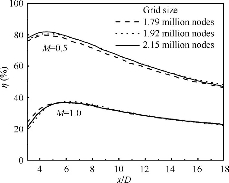
Fig. 2 Centerline film cooling effectiveness of cylindrical hole case with different grid sizes.
2.2. Turbulence model and validation
The commercial CFD software package Fluent 15.0 is used for the numerical simulation.Solutions of the Reynolds-Averaged Navier-Strokes (RANS) equations are obtained by using the finite volume method. Although the RANS method is not as accurate as DNS (Direct Numerical Simulation) or LES(Large Eddy Simulation), it is widely used to analyze flow fields in design, since DNS and LES methods require more powerful calculational capacity and considerably more calculation time.RANS methods can provide only averaged results and cannot correctly catch many flow details, but they have been proven to be useful in many practical applications,including the design and comparison of novel film cooling hole schemes. RANS models were adopted in many previous studies about swirling flow in gas turbine internal and film cooling passages.Choosing an appropriate turbulence model is important for getting accurate RANS results.The realizable k-ε model is chosen for this study. This model was developed by Shih et al.with the intent of offering viable solutions for jet-in-crossflow interaction by modifying the dissipation rate and eddy-viscosity equations. In validation studies, this model was confirmed to be more accurate in simulating separated flows and flows with complex secondary flow features.
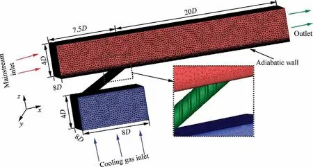
Fig. 1 Computation domain and boundary conditions.
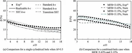
Fig.3 Numerical model validation by comparing laterally-averaged film cooling effectiveness of simulation and experimental50 results.
Results from the realizable k-ε model show the best agreement with experiments.Although the SST(Shear Stress Transport) k-ω model shows good agreement when x/D < 10, and the standard k-ω and standard k-ε models show some advantage over the realizable k-ε model when x/D> 10.The realizable k-ε model provides better overall performance. Besides,the realizable k-ε model can simulate the combined-hole film cooling cases well.Fig.3(b)shows comparisons of experimental (Exp) and numerical (Num) results for the combined-hole case for two different Mass Flow Ratios (MFR). The numerical results show good agreement with experimental results.Also, Refs. 26,27 show that the realizable k-ε model was chosen by others for successfully simulating influences of multiple jets on one another.Thus,the realizable k-ε model is chosen to do the present simulations. In this numerical study, pressure and velocity coupling is done by the SIMPLEC method. Spatial discretization of pressure, turbulence kinetic energy, and turbulence dissipation equations are second-order upwind.An enhanced wall function is employed. All the residuals are required to be lower than 10.
2.3. Geometries of studied cases
In this study, nine cases are considered. The film cooling hole shapes and the swirl directions of all the cases are shown in Fig. 4. The first is a cylindrical hole case with a diameter (D)of 20 mm, length (L) of 100 mm and inclination angle of 30°, which is the same as the validation case (Case 1C). Then swirling flow is introduced by using a spiral-threated hole with four threads. Three cases of different thread pitches (TP/L = 0.75, 0.50, 0.25) are simulated: Case 1C-S1, Case 1CS2, and Case 1C-S3. The Thread Pitch (TP) and hole length(L) are schematically shown for Cases 1C-S1 to 1C-S3 in Fig. 4. The threaded hole geometry might be difficult to machine for small film cooling holes, but it is simple to describe, and the swirl direction and pitch are easy to control.The purpose of this paper is to investigate the effects of swirling flow on film cooling and assess whether swirling flow can be used to enhance film cooling performance. In real film cooling applications, swirling coolant flows are usually introduced by the film cooling delivery hole internal geometry or the impingement effect at the film cooling hole entrance. The threaded hole geometry may be realized in the future by additive manufacturing.Based on the flow structure of film cooling with swirl, three double-hole cases with threaded holes are designed. Case 2C-S1 and Case 2C-S2 (see Fig. 4) have two threated holes located adjacent to each other spaced along the spanwise direction with a separation distance of two hole diameters (2D). The two holes have opposite swirl directions.A similar case (Case 2C-1) with two cylindrical holes located adjacent to each other spaced along the spanwise direction but without threads is simulated for comparison. Case 2C-S3 has two threaded holes located in line with one another with a separation distance of 3D in the streamwise direction. The two holes have opposite swirl directions. A similar case (Case 2C-2) with two cylindrical holes located in line with one another along the streamwise direction but without threads is simulated for comparison.Table 1 summarizes the film cooling hole geometry parameters of the nine cases.
3. Results and discussion
3.1. Single-hole film cooling
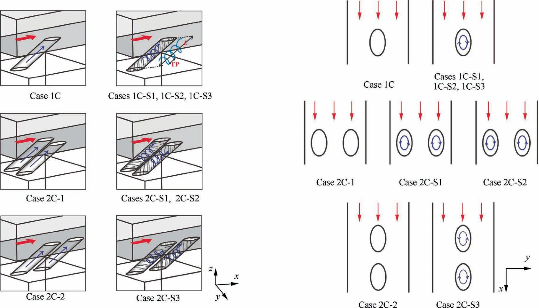
Fig. 4 Schematic diagrams of film cooling channels and swirl directions for all cases.
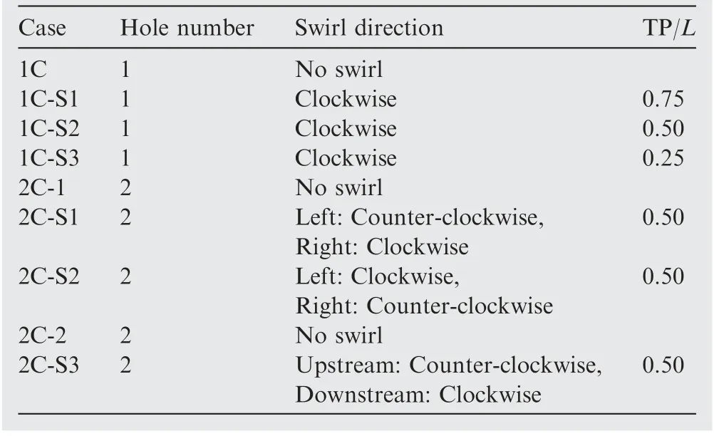
Table 1 Hole geometry parameters for various cases (clockwise vs counter-clockwise refers to circulation as viewed from above hole exit).
Fig. 5 shows computed film cooling effectiveness contours for single-hole cases at various blowing ratios. Case 1C shows effective film cooling surface coverage only when M = 0.5.The overall film cooling coverage decreases strongly with increasing blowing ratio.When M=1.0,the coolant jet blows off,then reattaches on the wall,but only the area near the centerline is cooled effectively. When M increases to 1.5, most of the coolant blows off the wall and film cooling effectiveness downstream becomes small. For Cases 1C-S1 to 1C-S3, swirling flow creates a pressure field that drives the downstream coolant from the centerline. The deviation is stronger with higher blowing ratios. The film first shifts in the negative y direction, then moves back due to pressure gradients in the main flow. When M = 0.5, film coverage of the swirl cases show little advantage over Case 1C. With increasing blowing ratio, high film cooling effectiveness is observed for Cases 1C-S1 and 1C-S2,while Case 1C-S3 shows lower performance than in Case 1C. The film blow-off and re-attachment is more prominent for Cases 1C-S1 and 1C-S3 when M=1.0 and 1.5,leading to more film coverage over the downstream area than in Case 1C.It can be concluded that film cooling with swirl can increase film cooling effectiveness at higher blowing rates, but swirl strength has a significant influence on film cooling performance. If swirl is too strong, film cooling performance is reduced by swirl.
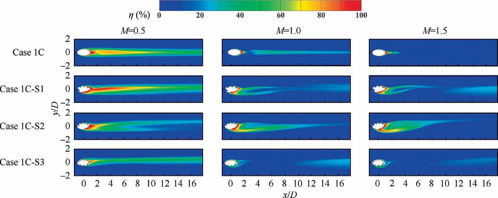
Fig. 5 Contours of film cooling effectiveness for single-hole cases with various blowing ratios.
Area-averaged film cooling effectiveness (η) values (–1.5 < y/D < 1.5 and –1.5 < x/D < 16) for Cases 1C and 1C-S1 to 1C-S3 are compared in Fig. 6. Case 1C shows decreasing film cooling effectiveness with increasing blowing ratio. The swirling cases also have decreasing film cooling effectiveness when the blowing ratio is increased from 0.5 to 1.0 but have similar values to their M = 1.0 case when the blowing ratio is increased to 1.5. Among the three swirling cases, Case 1C-S1 shows the highest film cooling effectiveness values when M = 0.5. Case 1C-S2 has improved film cooling performance over Case 1C only when M=1.0 and 1.5.When M =1.5,the swirling cases have higher film cooling effectiveness values than Case 1C, though Case 1C-S3 is only slightly higher.The largest improvement of effectiveness over the baseline case is achieved by Case 1C-S2,at M=1.5.An improvement of 157%.Fig.6 shows that a swirling jet can weaken the decline of film cooling effectiveness with increasing blowing ratios. Smaller swirling strengths can improve film cooling effectiveness when the blowing ratio is low (M = 0.5) while medium swirling strength yields higher effectiveness values at higher blowing ratios (M = 1.0 and 1.5). Swirl strength can be too high for achieving favorable film cooling results with swirl, as exemplified by Case 1C-S3 at M = 1.5.
Fig. 7 shows laterally-averaged (–1.5 < y/D < 1.5) film cooling effectiveness values for Cases 1C and 1C-S1 to 1CS3 with various blowing ratios (M = 0.5, 1.0 and 1.5) at different downstream locations (3 < x/D < 18). When M=0.5(Fig.7(a)),all the cases have decreasing effectiveness values along the streamwise direction, except for Case 1C-S3,but it has the lowest averaged film cooling effectiveness. Only Case 1C-S1 shows higher film cooling performance than the no-swirling case. When M = 1.0 (Fig. 7(b)), both Cases 1CS1 and 1C-S3 have larger film cooling effectiveness values over the downstream area (x/D > 11), which is attributed to more effective film reattachment.Compared with Case 1C,Case 1CS2 has improved film cooling effectiveness when x/D is small(x/D < 11), while Cases 1C-S1 and 1C-S3 show larger effectiveness values further downstream (x/D > 11). With the larger blowing ratio, M = 1.5 (Fig. 7(c)), swirling cases have higher film cooling performance than that of the nonswirling case, and, similarly, Case 1C-S2 has higher effectiveness values when x/D is small (x/D < 9) while Cases 1C-S1 and 1C-S3 have higher values further downstream (x/D > 9). It can be concluded that swirling cases can provide higher film cooling performance than that of the nonswirling case,especially at higher blowing ratios.Medium swirl strength leads to higher effectiveness values at areas just downstream of the hole, while smaller or larger swirl strengths lead to larger film cooling effectiveness values over areas further downstream.
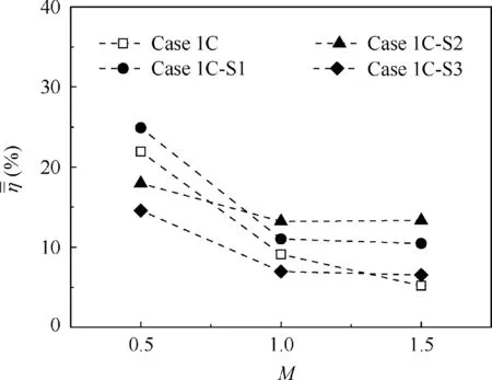
Fig. 6 Area-averaged film cooling effectiveness for single-hole cases with various blowing ratios.
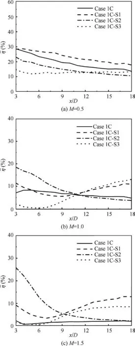
Fig. 7 Laterally-averaged film cooling effectiveness values downstream of film cooling hole for single-hole cases with various blowing ratios.
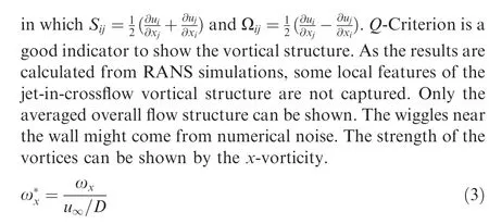
Fig. 8 displays iso-surfaces of the Q-criterion (Q = 10000)colored by the magnitude of dimensionless x-vorticity for Cases 1C and 1C-S2 at M=1.5.The Q-criterion is defined as:

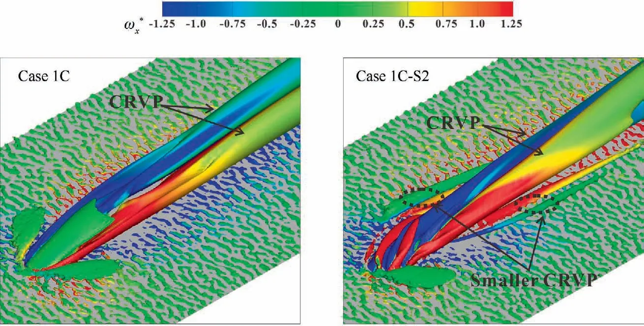
Fig.8 Iso-surfaces of Q-criterion(Q=10000)colored by magnitude of dimensionless x-vorticity for Cases 1C and 1C-S2 at M=1.5.
The typical Counter-Rotating-Vortex-Pair (CRVP) can be seen in Case 1C. It enhances mixing between the main flow and the coolant,bringing hot flow under the coolant film,lifting coolant film off the plate, finally leading to weakened film cooling performance.For Case 1C-S2,in which the coolant jet is a swirling flow, both the flow structure inside the channel and the interaction between coolant and main flow are different than observed in Case 1C in that different vortical structures are formed. Firstly, the symmetrical horseshoe vortices are not seen near the hole exit. Instead, many small vortices with opposite rotating directions are observed at the hole exit.Then,after interaction with the crossflow,two vortex branches with opposite rotating directions, similar to the CRVP,become dominant in the downstream flow field.However, different from the CRVP in Case 1C, the left branch (negative y direction)has larger vorticity than that of the right branch and is closer to the plate. This is because the right branch of the CRVP is lifted by the crossflow more than the left branch is lifted. Also, dissipation of the right branch is stronger than that of the left branch, making its vorticity value smaller at the same streamwise location. Another difference is that two smaller CRVPs are observed, as shown by the dash lines in Fig. 8. The smaller vortices near the left branch of the CRVP have the opposite rotation direction,which is beneficial toward weakening the mixing and lifting off the left branch.Therefore,the swirling cases have larger film cooling effectiveness values on the left side (negative y direction) and are more likely to have film attachment at the higher blowing ratio (M = 1.5).
Contours of dimensionless temperatures on downstream cross-sectional planes (x/D = 3 and 8) with velocity vectors for single-hole cases are shown in Fig. 9. The dimensionless temperature is defined as:

For Case 1C, the kidney vortex pair is shown by the vectors.For the swirl cases,the coolant first moves toward the left side(negative y direction),as shown in Fig.9 at x/D=3,then moves back to right side (positive y direction) as shown at x/D=8.This is consistent with the effectiveness contours shown in Fig. 5. The right side of the CRVP is lifted higher than the left side,and has lower dimensionless temperature values.This phenomenon is seen also in the Q-criterion of Fig. 8. On the left side of the CRVP, smaller vortices with opposite rotation direction to that of the left branch of the CRVP can be observed for Cases 1C-S1 and 1C-S2. This vortex helps keep the left branch of the CRVP attached on the plate and weakens mixing of the mainstream and coolant.Case 1C-S2 has a stronger vortex than Case 1C, while this vortex for Case 1C-S3 is too weak to be seen in Fig.9.As a result,Case 1C-S2 has more effective film attachment at the higher blowing ratio than seen in Cases 1C-S1 and 1C-S3.From Fig.9,we can conclude that for the swirling cases, the coolant will first move to the left side, then move back. The swirl cases have more effective film attachment and less mixing with the main flow due to small vortices with opposite rotating directions introduced by the swirling flow on the left side. The strengths of such vortices are consistent with swirl strength.
3.2. Double-hole film cooling
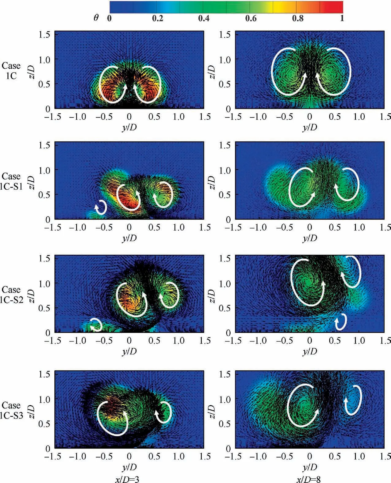
Fig. 9 Contours of dimensionless temperatures on downstream cross-sectional planes with velocity vectors for single-hole cases at M = 1.0.
The results in Section 3.1 are used to design some double-hole geometries for improving film cooling coverage and attachment due to interaction of vortices from the two holes. Film cooling effectiveness contours for double-hole cases at various blowing ratios are shown in Fig.10.For Case 2C-1,two cylindrical holes are located adjacent to each other along the spanwise direction, separated with a distance of 2D. The film cooling effectiveness distribution is almost the same as that of one cylindrical hole (Case 1C), as the coolant jets from the two holes cannot influence each other, even with the close distance of 2D. Only when M = 1.5 does coolant from the neighboring holes mix and reattach on the plate at a downstream location.For Case 2C-S1,the coolant jets interact with each other in the middle area of the two holes due to swirl.With increasing blowing ratio(M=1.0 and 1.5),this interaction takes place immediately downstream of ejection and improves film cooling effectiveness and attachment in the middle area, where Case 2C-1 has low film cooling performance.One thing to be noticed for Case 2C-S1 is that, with M = 1.5, the film cooling effectiveness contours are twisted,which is not common for a RANS simulation of film cooling.This might be because the vortices created by swirling jets are very complicated and unsteady. At higher blowing ratios,interaction of the two vortical fields even enhances this complexity, and the unsteadiness, making the film cooling effectiveness distribution contorted. For Case 2C-S2, swirl directions are opposite to those of Case 2C-S1. The coolant films first move away from each other,then mix further downstream between the two holes. At higher blowing rates, the coolant films blow off downstream. Therefore, downstream mixing cannot significantly improve film cooling performance.As a result, Case 2C-S2 can improve film cooling effectiveness and coverage only at lower blowing ratios than those found effective for the swirling single-hole cases. For two cylindrical holes located in two rows,adding swirl can improve film cooling performance, as shown by the results of Cases 2C-2 and 2C-S3. For the lower blowing ratio (M = 0.5), Case 2C-S3 has higher film cooling effectiveness and wider film coverage than those of Case 2C-2.Although the increased blowing ratio makes film coverage of Case 2C-S3 smaller,it shows a stronger tendency for film attachment than with the non-swirl case.Overall, using combined-holes with swirling coolant flow can improve film cooling performance by the interaction of coolant streams.
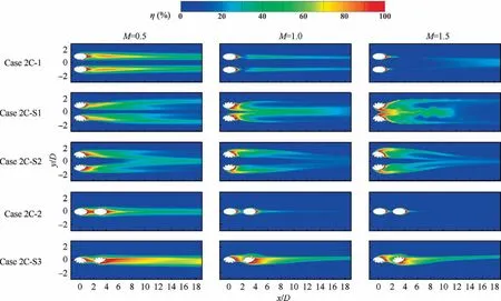
Fig. 10 Contours of film cooling effectiveness for combined-hole cases with various blowing ratios.
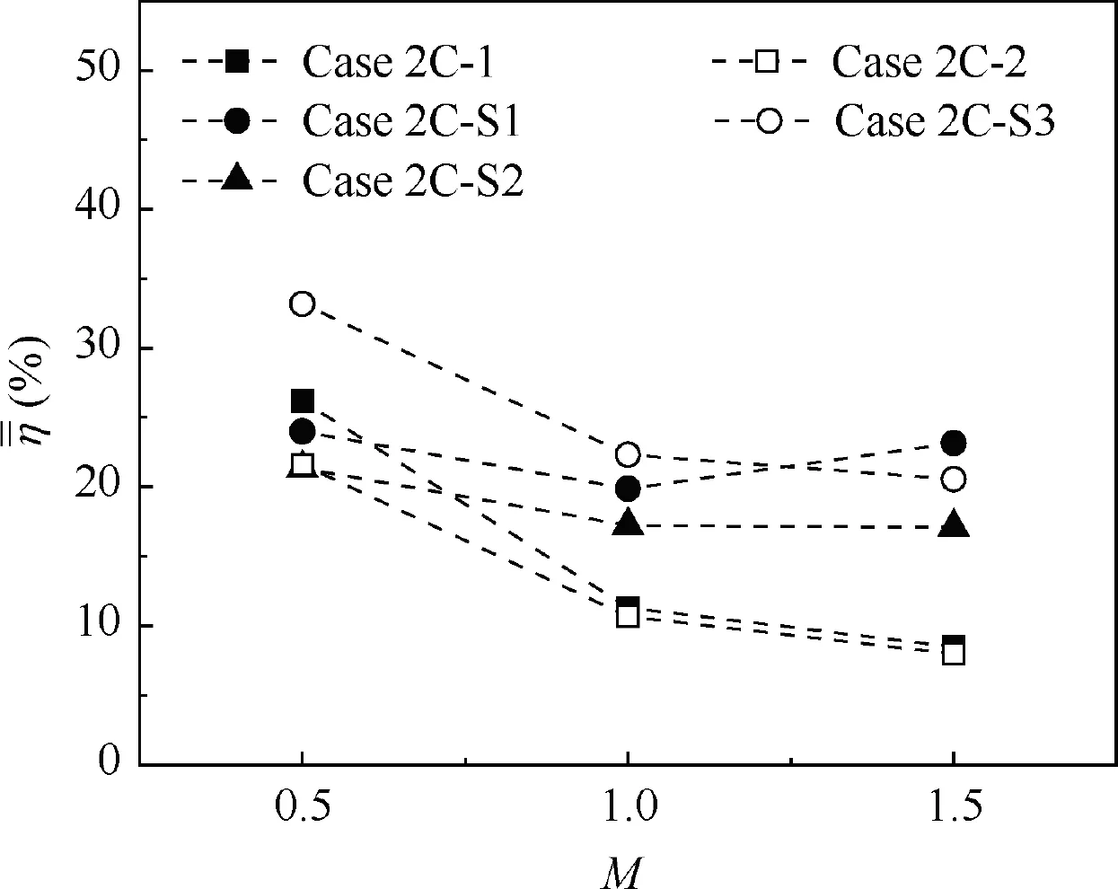
Fig. 11 Area-averaged film cooling effectiveness for combinedhole cases with various blowing ratios.
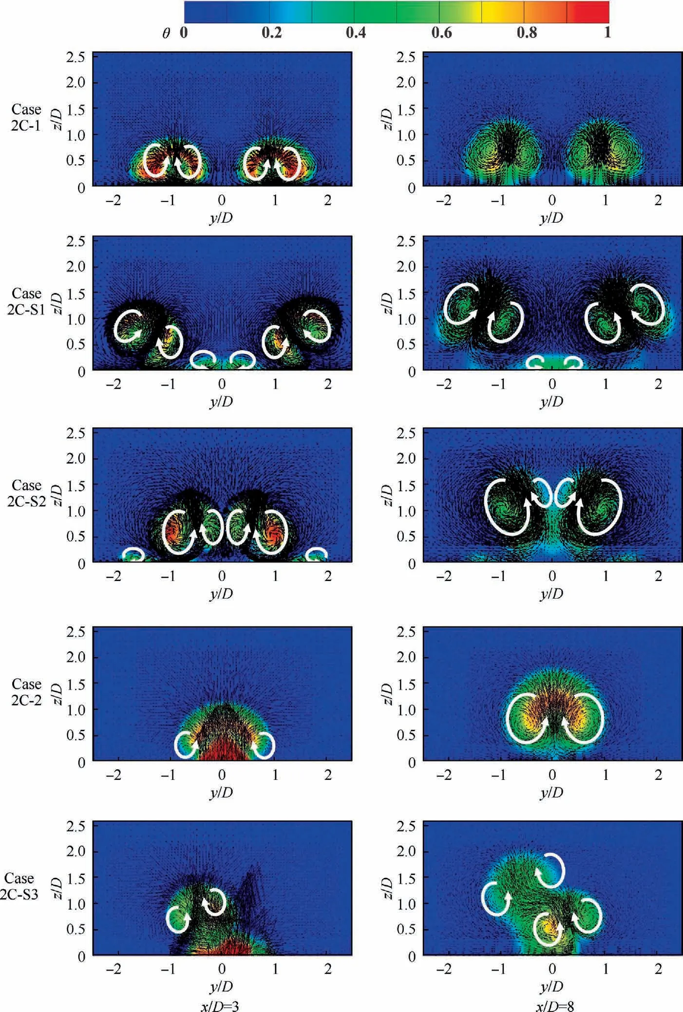
Fig. 11 shows area-averaged film cooling effectiveness values for Cases 2C-1 and 2C-2 and 2C-S1 to 2C-S3.The averaging area for Cases 2C-1,2C-S1 and 2C-S2 is–2.5 Fig. 12 shows laterally-averaged (–2.5 < y/D < 2.5 for Cases 2C-1, 2C-S1 and 2C-S2, –1.5 < y/D < 1.5 for Cases 2C-2 and 2C-S3) film cooling effectiveness values for combined-hole cases with various blowing ratios (M = 0.5,1.0 and 1.5) at different downstream locations (3 < x/D < 18). When M = 0.5, Cases 2C-S1 and 2C-S2 have lower film cooling effectiveness values than Case 2C-1. Case 2C-S3 has higher effectiveness values than those of Case 2C-S2 and the improvement is larger at downstream areas (x/D > 5)where the coolant jets from upstream and downstream holes begin to mix with each other. When M = 1.0, Cases 2C-S1 and 2C-S2 show higher laterally-averaged film cooling performance along the streamwise direction than that of Case 2C-2.The effectiveness values of Case 2C-S3 are still larger than those of Case 2C-2,but the improvement is not as large as that for M = 0.5. Case 2C-2 has lower film cooling effectiveness values at downstream locations (x/D > 5), which means that mixing of coolant from upstream and downstream holes without swirl effects reduces cooling performance.When the blowing ratio increases to 1.5, Case 2C-2 has almost no film coverage over the downstream area,while Case 2C-1 provides some film cooling protections due to mixing and reattachment.Cases 2C-S1 and 2C-S2 mainly increase the film cooling effectiveness when x/D<12 while Case 2C-S3 increases it over all downstream locations. The curve for Case 2C-S1 is consistent with the twisted film cooling effectiveness contours shown in Fig. 10. Fig. 12 Laterally-averaged film cooling effectiveness values downstream of film cooling hole for combined-hole cases with various blowing ratios. The iso-surfaces of Q-criterion (Q = 10000) (Eq. (2)) colored by the magnitude of dimensionless x-vorticity (Eq. (3))for Cases 2C-S1 to 2C-S3 with M = 1.5 are shown in Fig. 13, to show the vortical structure created by the swirling jets in crossflow. For Case 2C-S1, the swirling directions of the coolant jets from the two holes make the coolant film spread toward the middle. Also, there are two smaller CRVPs with opposite rotation directions introduced by the swirling flow interacting with each other in the mid region between the two holes, as shown by the dash line. As a result, coolant flows from the two holes mix with each other and cover the middle region, even at a high blowing ratio (M = 1.5). For Case 2C-S2, the swirl directions of the two holes are opposite to those of Case 2C-S1 and the coolant jets from the two holes first move away from each other,then return downstream.The right branch of the main CRVP of the left hole and the left branch of the main CRVP of the right hole have opposite rotation directions and mix in the middle area, as shown by the dash line. However, these two branches have already lifted away from the surface and dissipate strongly downstream.Finally, Case 2C-S2 increases downstream film cooling effectiveness, but the overall increase is less than that of Case 2CS1. For Case 2C-S3, the coolant jet from the upstream hole tends to move to the right while the coolant jet from the downstream hole tends to move to the left. As a result, the right branch of the main CRVP produced by the upstream jet meets the left branch of the main CRVP produced by the downstream jet, as shown by the dash line. These two vortices have different rotation directions and, thus, mix with and weaken each other, further weakening the mechanism of the CRVPs(enhancing mixing of the main flow and coolant and blowing off the surface at higher blowing ratios). This leads to improved film cooling performance over that in Case 2C-2. Fig. 14 shows contours of dimensionless temperature on downstream cross-sectional planes(x/D=3 and 8)with velocity vectors for the combined-hole cases. From the contours of Case 2C-1,one can see the CRVP created by each jet.They do not interact with each other. For Cases 2C-S1 and 2C-S2, the vortices created by the two swirling jets interact with each other between the two jets. The smaller vortices in the center region of Case 2C-S1 pull coolant toward the center and cover the plate, enhancing film cooling effectiveness and coverage in that middle area,as shown by Fig.10.The right branch of the main CRVP created by the left hole is stronger and is closer to the plate than the left branch; similarly, the left branch of the main CRVP created by the right hole is stronger and has the opposite swirling direction. Therefore, these two branches of the vortex push the small vortices in the middle to attach on the surface, making Case 2C-S1 to have effective cooling performance at the higher blowing ratio.For Case 2C-S2,the situation is opposite.The right branch of the main CRVP created by the left hole and the left branch of the main CRVP created by the right hole is lifted away from the surface. So, the coolant in the middle cannot cover the plate effectively. However,at a lower blowing ratio (M = 0.5), the vortices are weaker and have a lower tendency to lift off the plate.This interaction of vortices helps the coolant to cover the intermediate area for Case 2C-S2,as shown in Fig.11,for x/D=8 when M=0.5.These are the reasons that Case 2C-S1 has greater film coverage at higher blowing ratios while Case 2C-S2 has greater film coverage at lower blowing ratios. For Case 2C-2, the jet from the downstream hole pushes the coolant from the upstream hole away from the plate and forms a CRVP of larger scale,which is not favorable for film cooling. Swirling the jets improves the situation.The strength and location of the CRVP are changed by swirl, making the right branch of the main CRVP created by the upstream hole and the left branch of the main CRVP created by the downstream hole to move in opposite directions and interact with one another, while the other branches of the CRVPs are weaker due to the swirl.Finally,Case 2C-S3 shows greater coverage and more of a tendency for attachment than with Case 2C-2. Fig. 13 Iso-surfaces of Q-criterion (Q = 10000) colored by magnitude of dimensionless x-vorticity for Cases 2C-S1 to 2C-S3 at M = 1.5. Fig. 14 Contours of dimensionless temperature on downstream cross-sectional planes (x/D = 3 and 8) with velocity vectors for combined-hole cases with M = 1.0. This paper’s numerical simulations document the effects of swirl flow in coolant jets on film cooling performance. The numerical model employed was validated by experimental results.The influences of swirl strength and blowing ratio were studied.Adiabatic film cooling effectiveness and flow structure were calculated and analyzed.Based on flow structure of swirling jets in crossflow, three double-holes with swirl were designed for improving film cooling performance. The following conclusions are drawn from the results: (1) A swirling coolant jet can improve film cooling effectiveness at higher blowing ratios.The swirl strength has significant influence on film cooling performance. Smaller swirl strength can improve film cooling effectiveness at lower blowing ratios while medium swirl strength is more suited to higher blowing ratios. Swirl that is too strong will decrease film cooling performance. (2) Swirling coolant flow forces the coolant film to deviate off centerline. The deviation is stronger at higher blowing ratios. The coolant film shifts to one side in a direction that is based on the swirling direction.Downstream it returns under the pressure field from the main flow.Swirl also increases the tendency toward reattachment. (3) The vortical structure of film cooling with swirling coolant flow is different than the typical JICF structure.The main CRVP becomes asymmetric. The vorticity strength, scale, dissipation rate, and locations of the two branches of the CRVP are different. Additionally,smaller CRVPs are created near the main structure. (4) Double-hole designs can have further improvement in film cooling performance when using swirling coolant jets. Two adjacent holes with opposite swirl directions located along the streamwise and spanwise directions can enhance film cooling effectiveness and weaken film blow-off tendencies at higher blowing ratios,due to mixing of coolants and interaction of the vortices. The authors declare that they have no known competing financial interests or personal relationships that could have appeared to influence the work reported in this paper. This work was supported by Guangdong Basic and Applied Basic Research Foundation, China (No. 2019A1515111146),the Fundamental Research Funds for the Central Universities,China (No. 3102020HHZY030005), the Natural Science Basic Research Plan in Shaanxi Province of China (No. 2021JQ-104), the National Natural Science Foundation of China(No. 51676163), and the National 111 Project, China (No.B18041).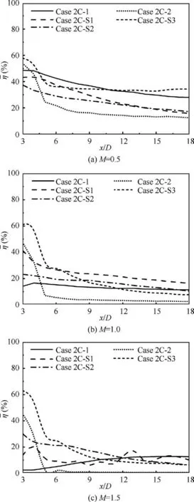

4. Conclusions
