Interaction formulae for buckling and failure of orthotropic plates under combined axial compression/tension and shear
Binwen WANG, Xingming CHEN,*, Xisheng SUN, Puhui CHEN,Zhe WANG, Y’nn CHAI
a Aeronautics Science and Technology Key Laboratory of Full Scale Aircraft Structure and Fatigue, Aircraft Strength Research Institute of China, Xi’an 710065, China
b Chinese Aeronautical Establishment, Beijing 100029, China
c State Key Laboratory of Mechanics and Control of Mechanical Structures, Nanjing University of Aeronautics and Astronautics, Nanjing 210016, China
KEYWORDS Buckling;Combined loads;Failure;Interaction formulae;Orthotropic plate
Abstract An interaction function was constructed based on the axial compression/tension and shear loads of orthotropic plates. The coefficients of the polynomial function were determined by uniaxial test results. Buckling interaction and failure interaction formulae under combined axial tension/compression and shear loads were established. Based on the uniaxial load test results of orthotropic plates, the buckling load and bearing capacity under any proportion of the combined loads could be predicted by using the proposed interaction formulae. The buckling interaction curves and failure envelopes predicted by the proposed interaction formulae were in excellent agreement with the test results.
1. Introduction
Composite materials have been widely used in the aircraft and aerospace fields due to their low weight, low cost, good designability, and manufacturability. Many researchershave conducted meaningful work on the design,analysis and testing of composite structures. However, due to the imperfections of composite application technology and conservative design criteria,the weight reduction effect of composite structures is not ideal, especially for some thin-walled stiffened panels.The thin-walled stiffened panels commonly used in aircraft fuselages and wings have a long postbuckling progression.The skin of metal stiffened panels used in the wings of subsonic aircraft usually allows local buckling to occur at about 50%of the ultimate load.However, skin buckling is not allowed under limited loads in the current design criteria for composites. Therefore, solving the problem of the postbuckling of composite panels can greatly reduce the weight of aircraft structures. Moreover, considerable research has been carried out in this field in the past decade.Many buckling and postbuckling experiments and analyses of composite stiffened panels under uniaxial compression or shear loads have been conducted,and good results have been obtained. However,the real load cases of aircraft panels are usually not under uniaxial compression or shear loads but combined loading conditions. For example, the upper skin of the wing mainly bears combined compression and shear loads, while the lower skin mainly bears combined tension and shear loads.The same loading conditions occur in the fuselage.A combined compression and shear load is the most severe loading condition for structural stability, and the structure may buckle when either type of load is lower than the critical buckling load. Tensile loads do not trigger compression-driven buckling but instead impede the development of shear-driven buckling.To achieve structural stability during the design process,an interaction formula is a fast and effective means to obtain the buckling critical load of a plate under combined loads,which can be used for the preliminary design and rapid optimization of a panel structure.In addition,in the process of aircraft development, it is necessary to carry out a large number of panel verification tests of the fuselage and wings under combined loads.However,the cost and time required for tests under combined loads are two of the main constraints of aircraft development.By using a reliable interaction formula, the buckling behavior of a panel under combined loads can be predicted only by unidirectional load tests,which can effectively reduce the number of tests and the cost of verifying a design.Therefore,for many years,interaction formulae that can predict the critical value of buckling under different proportions of combined axial tension/compression and in-plane shear loads have been studied.For long isotropic plates under combined uniaxial compression and shear loads, Stowell and Schwartz,based on the energy method, found that the work done by the combined compression and shear loads per half wavelength was equal to the sum of the strain energy of the plate and the stiffener per half wavelength by assuming that the constraint of the stiffener on the plate was independent of the buckling wavelength. Based on this result, an interaction formula for evaluating the conditions of combined compression and shear loads for an infinitely long, flat plate was deduced to be approximately as follows:

where R represents the ratio of the critical load under a combined loading state to the critical value of the corresponding load acting alone, and subscripts x and s denote the axial and shear loads, respectively. Stowell and Schwartzfound that Eq. (1) yielded excellent agreement, to within 1%, with their numerical results. However, in theory, it only applies to long isotropic plates.
Timoshenko,Way,and Johnsonet al.provided buckling data for long isotropic plates subjected to combined pure in-plane bending and shear loads. The first two authors presented their results in terms of the interaction formula

where subscript b represents pure in-plane bending. These authorsclaimed that an acceptable accuracy was obtained for simply supported and clamped boundary conditions.However, this claim was assessed in another study,and it was found that a conservative estimate of buckling load was calculated using Eq. (2) with an accuracy of 20%.
The interaction formulae given by Eqs. (1) and (2), especially the former, were deduced by mathematical derivations based on reasonable assumptions, which have good universality in the applicable range and are widely used in stability calculations under combined loads for isotropic stiffened panels. Nevertheless, they are only applicable to isotropic plates due to the limitations of the fundamental hypotheses.Therefore, considerable improvements based on the previous work were achieved later by other scholars to allow these formulae to be more effectively applied for anisotropic plates. The convexity/concavity of the interaction curve will be influenced by the exponents in Eq. (1): the larger the exponents, the more the interaction curve bulges outward.Therefore, the subsequent improvements based on this interaction formula basically involved the modification of the exponents.
Weaver and Nemethpresented a buckling interaction formula for long orthotropic plates with either simply supported or clamped edge conditions under combined loads by modifying the exponent of the shear term in Eq. (1), as follows:

where Drepresents the flexural stiffnesses of classical laminated-plate theory.
It was further shown that β had a well-defined range of values given by 0<β<3,and β=1 for isotropic materials and quasi-isotropic materials. The modification of the exponent of the shear term was determined by characterizing the nondimensional parameter β for orthotropic materials. This was done by a fit to the numerical solutions obtained by using the Rayleigh–Ritz method.Different anisotropic materials correspond to different β values, which can be used to characterize the effect of the anisotropy of materials on the buckling interactions under combined loads.
Beerhorst and Seibaldemonstrated an engineering analysis method applied to infinitely long plates under a combined loading condition of homogeneous uniaxial compression for longitudinal and in-plane shear loads, in which the plate strip was assumed to be elastically restrained against rotation at the longitudinal edges. The exponent of the shear term of the buckling interaction formula under combined compression and shear loads was modified for anisotropic plates. In addition, an equation similar to Eq. (3) presented by Weaver and Nemethwas obtained:

where β is the same as that in Eq.(4).Different anisotropic plies have different exponents. The bandwidth of the relative error can be reduced from about 5.5% to less than 1.5% by using the modified interaction formula derived in this work.However, this method only involved changing the fitting coefficient of the shear term from linear to quadratic, which was not verified for combined compression and shear loads due to the lack of test data.
The interaction formulae applied to anisotropic plates under combined loads proposed previouslywere all based on the fitting of experimental or numerical results or empirical modifications of previous work, which allowed Eq. (1) to be applied for anisotropic plates. Johnsfound that Eq. (1) for isotropic plates was also applicable to orthotropic plates,which was confirmed by citing the results from the fifth chapter of Ref.,at least for combined compression and shear loads.
For the stability design of orthotropic plates,especially the postbuckling design, the failure envelope of panels should be calculated as well as the buckling interaction curve under combined loads. However, the failure envelopes have been mainly obtained by biaxial testsor finite element simulations.Until now, an interaction formula for failure under combined loads that can predict the failure envelope more accurately has not been found.
In the present study,interaction formulae were constructed by using axial tension/compression and in-plane shear loads for orthotropic plates,which were then expanded into a quadratic polynomial as a power series. The undetermined coefficients of the polynomial were determined by using the mathematical theorem and uniaxial test results. The buckling interaction and failure interaction formulae of orthotropic plates under combined loads were constructed.The predictions of the buckling interaction curves and failure envelopes were in excellent agreement with the combined compression and shear test data of composite panels with symmetric and balanced lay-ups. The methods and results in this paper may have certain guiding significance for the deduction of interaction formulae under other types of combined loads.
2. Computation scheme
Axial compression and shear are the two main types of loads that cause the failure of a plate. Axial tension does not trigger buckling of the plate in the load direction.Instead,the critical shear will be increased by the tension.Tension impede the development of shear-driven buckling.Therefore,the buckling interaction function Fof an orthotropic plate can be written as a function of the load components on the in-plane compression/tension Nand shear N. It is expressed as follows:
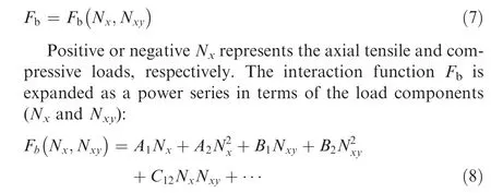
where A, B, and Care undetermined coefficients, ‘‘...”represents higher-order terms.
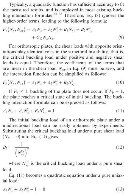
According to the physical mechanism of an orthotropic plate under axial loads, the quadratic equation only has one positive and one negative real solution. The positive solution is the critical buckling load under tension, while the negative solution is the critical buckling load under compression.Because the plate will not buckle under a tensile load,the critical buckling load under a tensile load is infinite.According to Vieta theorem, the two solutions (denoted as Nand N) of Eq. (13) satisfy the following conditions:

Hence, the buckling interaction formula of orthotropic plates under combined axial compression/tension and shear loads can be written as
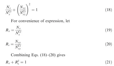
Eq. (21) is completely consistent with the buckling interaction formula under combined compression and shear loadscommonly used in engineering applications. In this paper,another rational mathematical derivation process of the buckling interaction formula is given,which is extended to cover the case of combined axial and shear loads under tension for orthotropic plates,or composite structures with balanced symmetric lay-ups.
3. Failure interaction formula
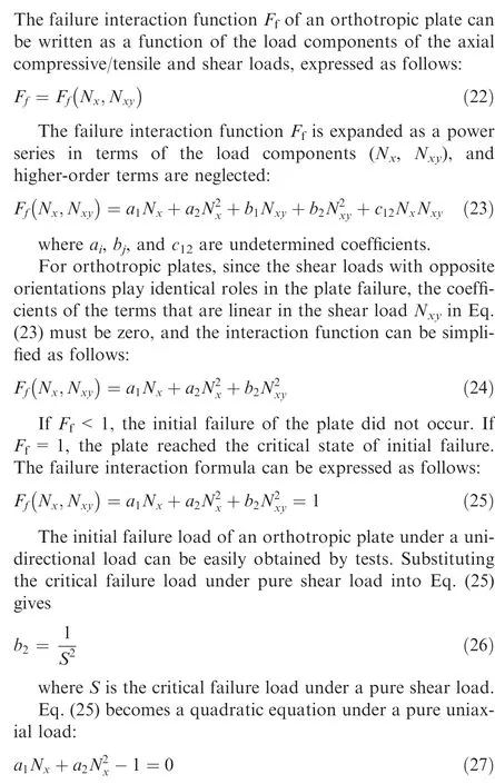
Substituting the uniaxial tensile failure load T and uniaxial compression failure load C into Eq. (27) yields the following:
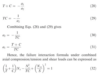
The failure envelopes of orthotropic plates under combined axial compression/tension and shear loads can be calculated by Eq.(32)through uniaxial tension,compression,and pure shear load tests. Because the tensile strength of an orthotropic plate is much larger than the compressive strength, therefore, it can be assumed that

4. Experimental verification
4.1. Specimen configuration and experimental method
To verify the validity of the interaction formulae,buckling and failure tests of five kinds of Ω-stringer stiffened composite panels with symmetric and balanced lay-ups under combined compression and shear loads were carried out. These composite laminates with symmetric and balanced lay-ups were approximately orthotropic plates.
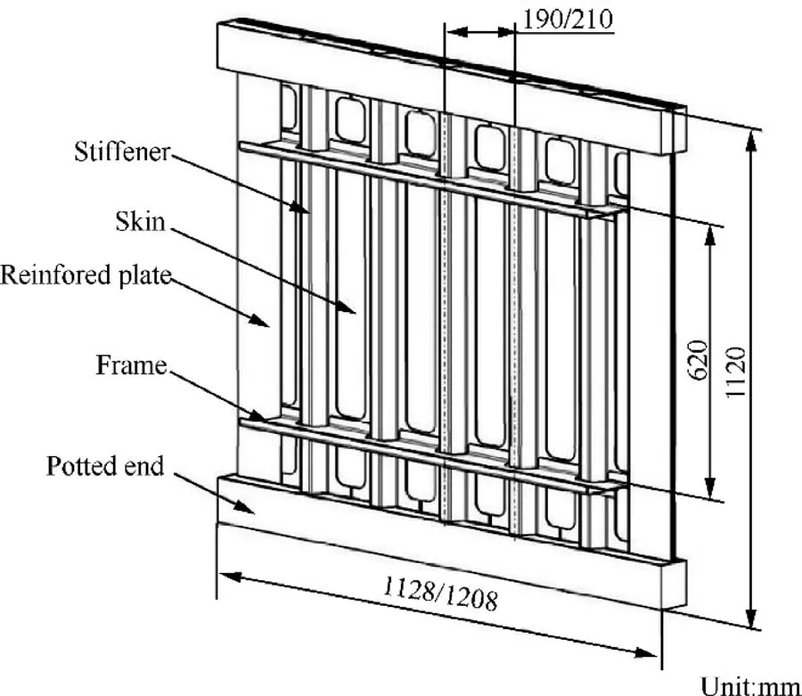
Fig. 1 Structural configuration of panel.
The stiffened panel was mainly composed of the skin, stiffeners, frames, reinforced plates, and potted ends, as shown in Fig.1.Each specimen was a flat panel stiffened by five stiffeners with Ω-shaped cross sections along the longitudinal direction and two frames along the transverse direction. The stiffeners, which were bonded to the skin by adhesive, were symmetric with respect to the longitudinally symmetric axis and equally spaced with an interval of 190 or 210 mm. The frame comprised an L-shaped shear web and a Z-shaped floating frame, which were bolted together. The frames were made of an aluminum alloy (2024-T42). The skin, stiffeners, and reinforced plates were all made of M21E/IMA. The material properties are listed in Table 1. The lay-ups and thickness of the specimen are given in Table 2.The 0°direction of the plies was the same as the longitudinal direction of the stiffener.
To ensure that the initial failure did not occur at the loading or constraint edge of the specimen, two pieces were bonded at the loading or constraint regions of the front and back of the skin,and the reinforced plates had the same lay-up as the skin.The upper and lower ends of the specimen were potted ends,which were filled with resin in a steel box.
Combined compression and shear load tests were conducted on a new combined loading experiment system designed by the Aircraft Strength Research Institute of China.The experimental system consisted of compression and shear loading components, as shown in Fig. 2. The loading components could apply compressive and shearing loads simultaneously, and arbitrary proportions of the combined loads could be obtained. The shear loading component was a selfbalancing frame. The uniformly distributed shear load was applied actively on both sides of the specimen by the loadequalizer, and the shear load was applied passively on both the upper and lower ends by the self-balancing frame. The operating principle of the experiment system is described in Ref. 48
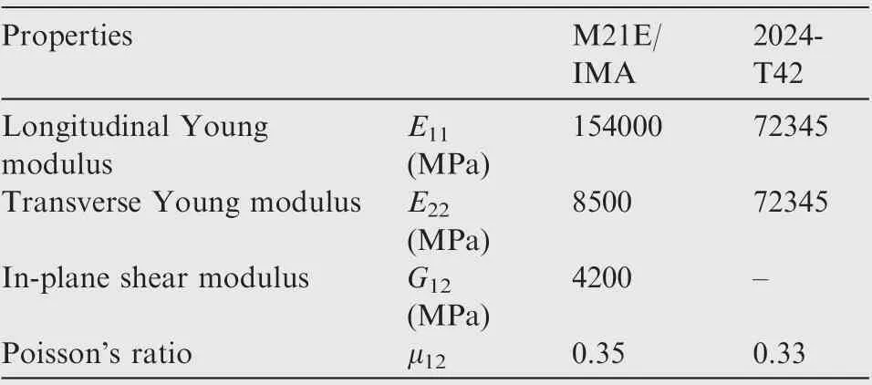
Table 1 Elastic properties of stiffened panel.
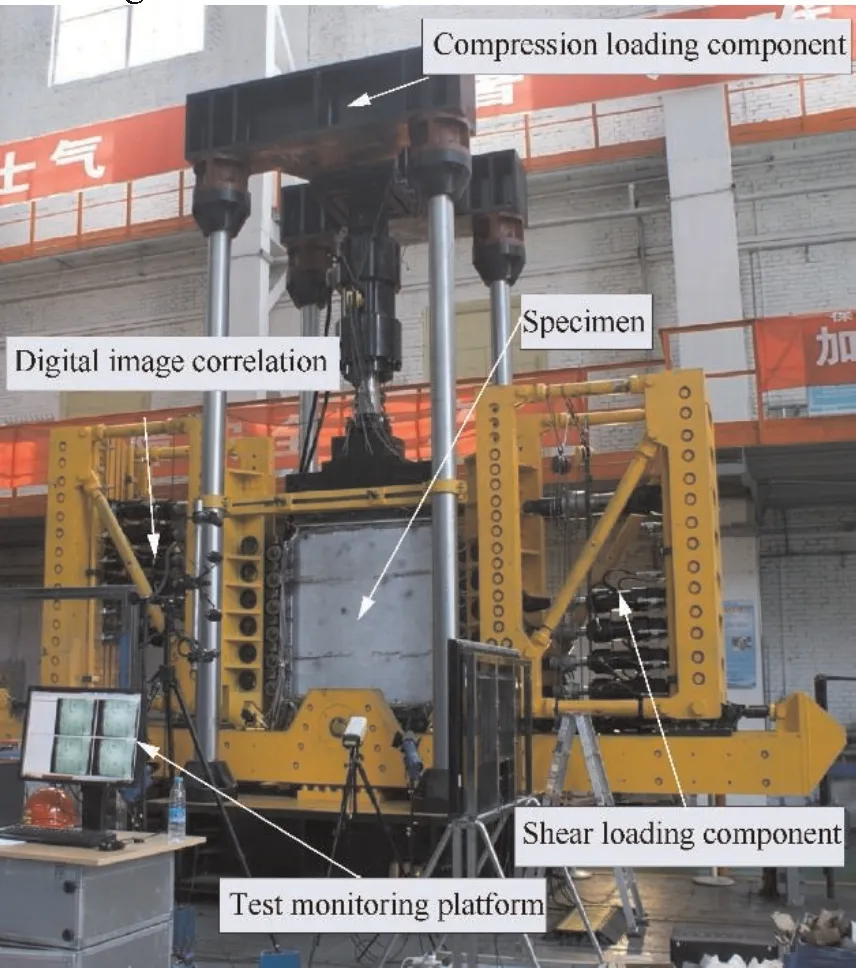
Fig. 2 Combined compression and shear loading test system.
The stiffened panel was clamped on the substructure of the experimental loading system by an angle box. The panel was supported with three free sides and one clamped side on the bottom.To avoid unnecessary global buckling of the specimen during the test, the out-of-plane displacement of the two sides of the floating frame and the upper potted end were constrained by the servo support component, which could move freely in the plane parallel to the skin. The support details are shown in Fig. 3.
4.2. Buckling interaction formula verification
For four configurations of the stiffened panels, the buckling tests under five ratios of combined compression and shear were carried out, including uniaxial compression and pure shear tests. The test results are shown in Table 3. The predicted buckling interaction using the formula proposed in this paper is compared with the test results,as reported in Fig.4.The pre-dicted buckling interaction was in excellent agreement with the experimental results.For specimen P2,with a compression-toshear ratio of 2:1, the prediction was larger than the experimental result. However, this data was not on the curve fitted by the other test results. Thus, the error was mainly caused by the experiment. It was impossible to verify the buckling interaction formula under combined tension and shear loads due to the lack of tension test data. Nevertheless, the panel could not buckle under an axial tensile load, and the tension could improve the shear buckling load, which is consistent with the trend predicted by the interaction formula in Fig. 4.

Table 2 Dimensions of stiffened panels.
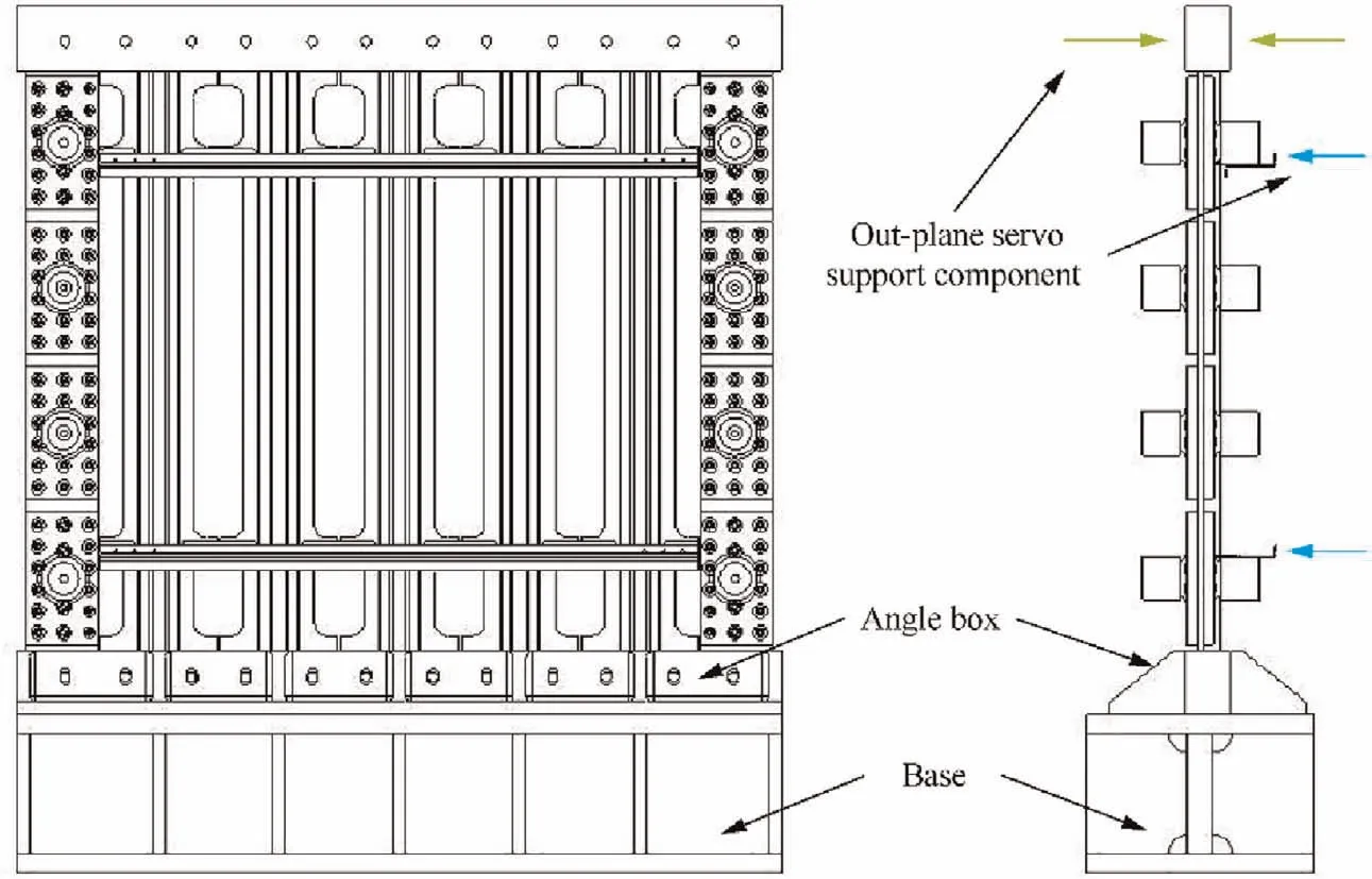
Fig. 3 Stiffened panel supports and constraints on loading test system.

Table 3 Initial buckling loads of stiffened panel under combined compression and shear.
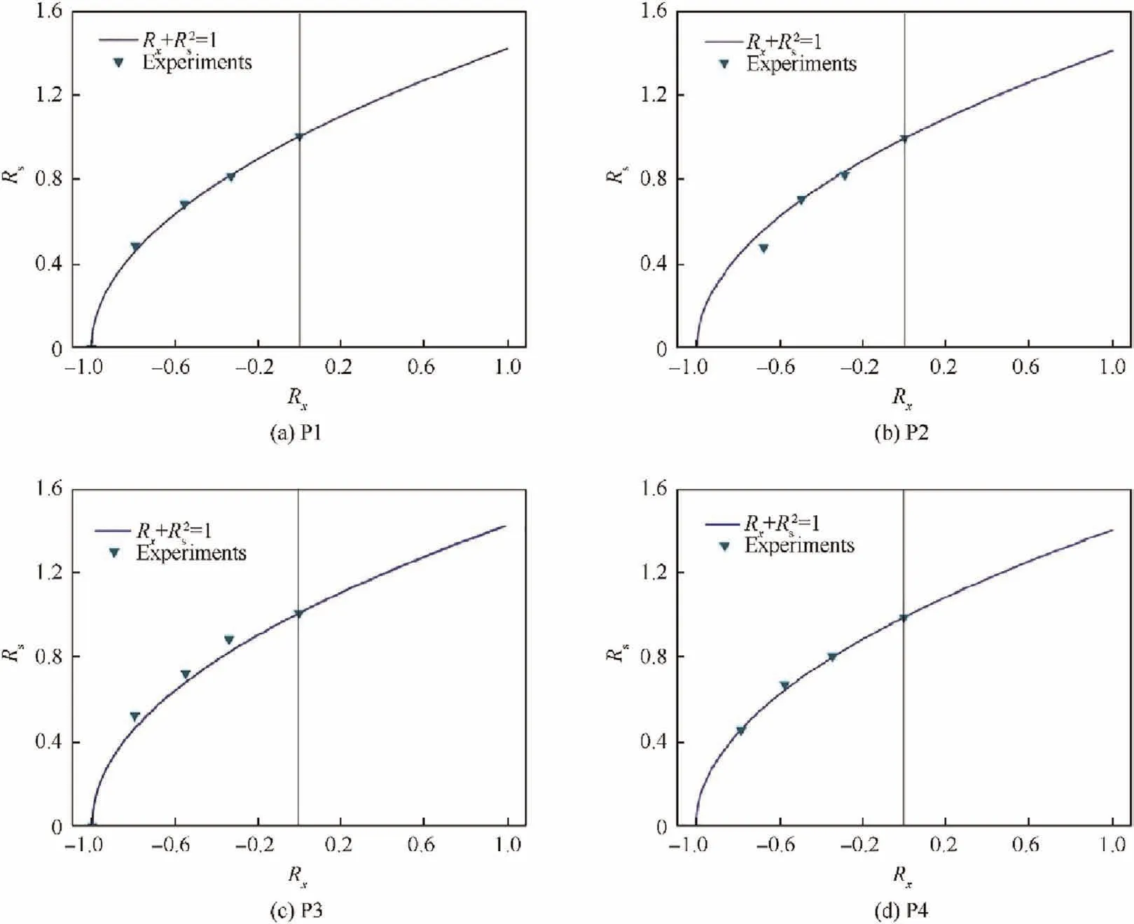
Fig. 4 Comparison of predicted and experimental buckling interaction curves under combined compression and shear.
4.3. Failure interaction formula verification
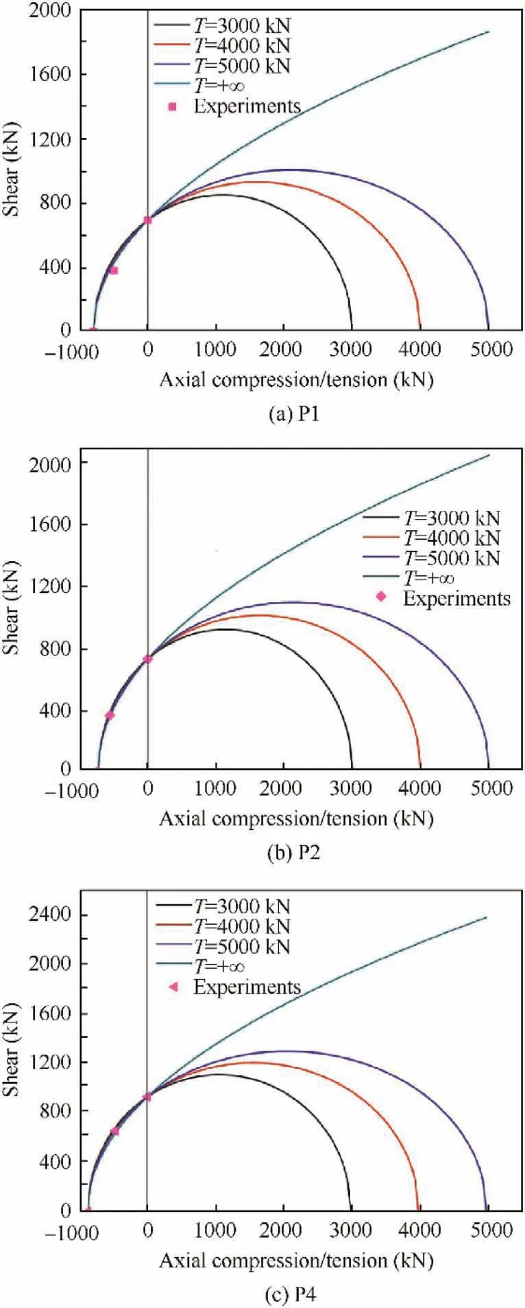
Fig. 5 Comparison of predicted and experimental failure envelopes under combined compression and shear loads.
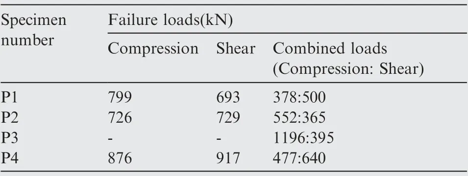
Table 4 Failure loads of stiffened panels.
The failure envelopes of the stiffened panel predicted by the proposed interaction formulae are shown in Fig.5.Under four uniaxial tensile failure loads, the failure envelope of the stiffened panel in the compression–shear quadrant did not change significantly. Therefore, when the uniaxial tensile strength of the stiffened panel is much greater than the compressive strength, its influence on the failure envelope under combined compression and shear loads can be ignored. Fortunately, the tensile strengths of composite stiffened panels are generally much greater than the compressive strengths. Therefore, Eq.(34), in which the tension term of Eq. (32) is neglected, is reasonable for engineering applications. However, the difference between the failure envelopes is evident under combined tensile and shear loads. The experimental verification of the failure envelope in the tensile–shear quadrant will be carried out in future work.
Under the combined tension and shear loads, tension can still increase the shear failure load. However, when the tensile load increases to a certain extent, coupled tensile and shear damage occurs, and the curve begins to decline until pure tensile failure occurs.With the increase in the tensile strength,the shear failure load also increases.Therefore,in the design of aircraft structure,the stability is generally not considered under a combined tension–shear load.
After the buckling test, the above four types of panels were subjected to postbuckling failure tests under pure compression and pure shear, as well as a combined compression–shear load. The test results are shown in Table 4.The failure test data of the composite panel were identical with the failure envelope predicted by the proposed interaction formulae. The P3 specimen was not included in the comparison due to the lack of uniaxial load test results.Nonetheless, the validity of the proposed failure interaction formula of the orthotropic plate, to some extent, was verified. However, the validity of the predictions under combined tension and shear loads should be further examined due to the lack of test results.
5. Conclusion
The buckling and failure interaction formulae of orthotropic plates under combined loads were constructed by considering axial tension/compression and in-plane shear loads of an orthotropic plate from a mathematical perspective based on the principles of analytic geometry. A traditional buckling interaction formula (Eq. (1)) was extended to cover the case of combined axial and shear loads, including tensile loads,for the orthotropic plates. The buckling interaction curves of the orthotropic plates predicted by the buckling interaction formula were in excellent agreement with the test results under combined compression and shear loads.
The bearing capacity of a plate with an arbitrary ratio of combined axial and shear loads can be determined by the proposed failure interaction formulae through uniaxial tension,compression, and shear load test results. Moreover, when the tensile strength of the panel is approximately infinite, the failure interaction formulae under combined compression and shear loads still have sufficient accuracy for engineering calculations. The failure envelopes predicted by the proposed interaction formulae were in excellent agreement with the experimental results under combined compression and shear loads.
The interaction formulae under other types of combined loads can be easily obtained by using the methods proposed in this paper.
The authors declare that they have no known competing financial interests or personal relationships that could have appeared to influence the work reported in this paper.
 Chinese Journal of Aeronautics2022年3期
- Chinese Journal of Aeronautics的其它文章
- Flow response hysteresis of throat regulation process of a two-dimensional mixed-compression supersonic inlet
- A step parameters prediction model based on transfer process neural network for exhaust gas temperature estimation after washing aero-engines
- Recent progress in flexible supporting technology for aerospace thin-walled parts: A review
- Numerical investigation of dynamic stall suppression of rotor airfoil via improved co-flow jet
- A refined design method for precoolers with consideration of multi-parameter variations based on low-dimensional analysis
- Solar-tracking methodology based on refraction-polarization in Snell’s window for underwater navigation
