A refined design method for precoolers with consideration of multi-parameter variations based on low-dimensional analysis
Hui LI, Zhengping ZOU,c,*, Yumin LIU
a National Key Laboratory of Science and Technology on Aero-Engine Aero-thermodynamics, School of Energy & Power Engineering, Beihang University, Beijing 100083, China
b Advanced Jet Propulsion Creativity Center, AEAC, Beijing 101304, China
c Research Institute of Aero-Engine, Beihang University, Beijing 100083, China
d International School, Beihang University, Beijing 100083, China
KEYWORDS Compact heat exchangers;Heat exchanger design;Low-dimensional segmented model;Non-uniform inflow;Precooled engine;Thermophysical properties variation
Abstract The precooler is a distinctive component of precooled air-breathing engines but constitutes a challenge to conventional thermal design methods. The latter are based upon assumptions that often reveal to be limited for precooler design. In this paper, a refined design method considering the variations of fluid thermophysical properties,flow area and thermal parameters distortion,was proposed to remediate their limitations.Firstly,the precooler was discretized into a fixed number of sub-microtubes based on a new discretization criterion.Next,in-house one-dimensional(1D)and two-dimensional (2D) segmented models were established for rapid thermal design and precooler rating with non-uniform airflow, respectively. The heat transfer experimental studies of supercritical hydrocarbon fuel were performed to verify the Jackson correlation for precooler design and the in-house models were validated against the reported data from open literature.On this basis,the proposed method was employed for the design analysis of hydrocarbon fuel precoolers for precooled-Turbine Based Combined Cycle (TBCC) engines. The results show that the local performance of precoolers is intrinsically impacted by the aforementioned three variations.In the case study,the local heat transfer performance is drastically affected by coolant flow transition.While the circumferential temperature distortion of airflow is weakened by heat transfer.With consideration of additional parameter variations, this novel method improves design accuracy and shortens the design time.
1. Introduction
Precooled air-breathing engines are promising propulsion systems to achieve low cost, efficiency and environment-friendly aerospace transportation due to its reusable features, superior performance and use of clean fuels.Since the adoption of many relatively mature technologies, the distinctive component of the precooled air-breathing engine is a compact precooler, which cools high-temperature incoming airflow with the high power/weight ratio and low pressure loss.By introducing this high-performance heat exchanger,precooling technology has been confirmed to increase the thrust and the specific impulse of Air-Turbo Ramjet engine with Expander Cycle(ATREX engine)by about 80%and 25%,respectively.Moreover,precooling technology opens up an effective way to solve the problem of thrust gap in Turbine Based Combined Cycle (TBCC) engines.When using the hydrocarbon fuel as coolant, the flight Mach number of an existing turbojet could be expanded to 3.0–4.0 by the precooler, instead of further researching high speed turbojets. For example, a Mach 5.0 precooled-TBCC prototype was well tested by Hermeus Corporation and the precooling technology ensures a conventional turbojet successfully works at the flight condition greater than Mach 3.2.This advantage further intensifies the demand for precooler studies, especially with hydrocarbon fuel coolant.
Precooler studies are important but costly by nature.Thus,the growing success of the precooling technology relies on a practical and reliable precooler design method.So far conventional heat exchanger design methods are flawed as they do not incorporate the crucial multi-parameter variations, i.e. the fluid thermophysical properties,flow area and thermal parameters distortion, during the actual operation of precoolers.In that view, there is a necessity to propose a refined design method that accounts for these variations while maintaining simplicity.
Typically, microtubes, supercritical pressure coolant and cross-flow arrangement are incorporated in an advanced precooler to offset the engine performance drop caused by its extra mass and induced pressure loss.By utilizing these features, three models of tubular precoolers used in the ATREX engine were designed and tested by the ground experiments.Nevertheless, it is revealed that their actual heat transfer rate falls below the theoretical predictions, and one of the potential causes could be the non-uniformity of airflow.The airflow distortion in the precooler plays a crucial role in its thermal performance, and in turn the nonuniformity is also changed by the heat transfer. Although the axial non-uniformities of airflow are thoroughly studied in previous worksand can be improved by a reasonable outer shell design,the circumferential distortion in precoolers is less understood and is often inevitable, especially for the temperature distortion caused by ingesting exhaust gas.However, the widely used zero-dimensional (0D) heat exchanger design methods completely ignore the impacts of nonuniform inlet conditions.
Aside from the non-uniform airflow, there are two other critical parameter variations in the precooler that incapacitate the 0D design methods.First,the actual flow area contraction due to the radial airflow is intrinsically not compatible with the fixed cross-sectional area assumption which is generally utilized.Second, huge temperature of hot airflow changes over the precooler depth and the variation in thermophysical properties is not negligible.For example, owing to the combined effects of increased density and diminished flow area, the airflow velocity might change non-monotonically,which will evidently complicate the flow characteristics and the precooler vibration assessment. It was confirmed by Gu and Minthat the ignorance of airflow properties variation results in 7%–14%and 47%–80%overestimations for heat transfer and pressure drop, respectively. As for a hydrocarbon fuel precooler,Fig. 1 shows the density (ρ), specific heat at constant pressure(c),thermal conductivity(λ)and viscosity(μ)of typical hydrocarbon fuels under supercritical pressure.The drastic change of fuel properties in a real operating condition involving high heat flux and heat transfer rates invalidates the conventional Nusselt number correlations and constant specific heat assumption.Owing to these different points, a new design method for precoolers is required as advanced by Lee et al.
Extensive efforts on the precoolers design, involving new design criterion,sensitivity analysis of design parametersand structural design scheme,etc. have been given to advance the precooling technology to a higher level. Design solutions of the Synergetic Air-Breathing Rocket Engine(SABRE)precooler were clarified by Webber et al.Yu et al.performed a precooler-design and engine-performance coupling optimization by using the Log-Mean Temperature Difference (LMTD) design method. The similar design method was also utilized by Zhang et al.to model the precooler for deeply precooled air breathing engines. However, most of these works relied on the conventional LMTD design method and the Effectiveness-Number of Transfer Units (ε-NTU)design method.These prominent 0D design methods are capable of the qualitative analysis of precooler performance, but the assumptions of constant fluid properties, uniform heat transfer surface area and inflow are intrinsically oversimplified for the precooler precise design. Ferna´ndez-Villace´ and Paniaguaproposed an enhancement based on the subdivision of the precooler for SABRE into numerous segments such that the variation of fluid properties is accounted, but the uniform inlet conditions and flow area assumptions were still used.This concept is part of the segmented design models widely utilized in other types of compact heat exchangers for supercritical carbon dioxide power cycle and aero-engine cycle.However,these compact heat exchangers are actually simpler as the varying flow area and inlet distortion are also minimized during thermal design. Therefore, the cited segmented design models and their discretization criteria are unadapted for the design of precoolers.
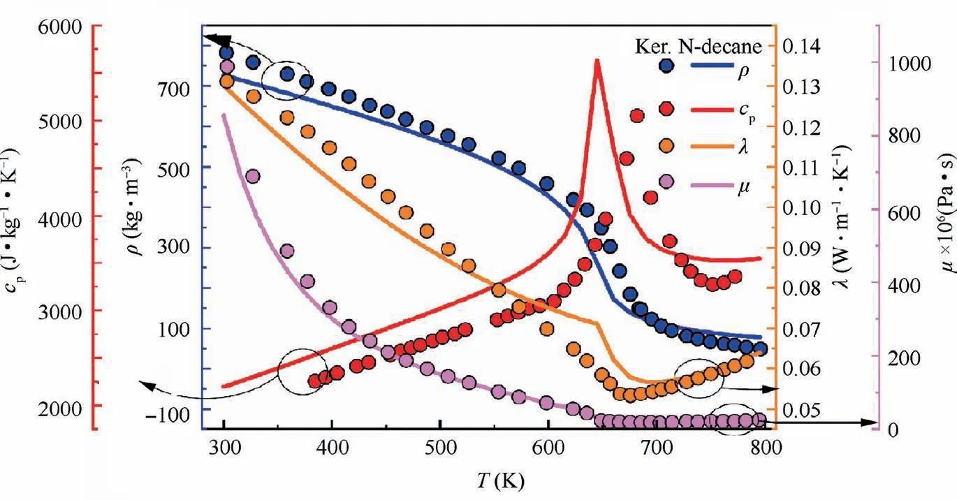
Fig. 1 Thermophysical properties variations with temperature for typical hydrocarbon fuels at 3 MPa (aviation kerosene19 and ndecane20).
To address these issues,the Computational Fluid Dynamics(CFD) approach is introduced in the precooler design procedure. This numerical approach not only contributes to rate the precooler with complex configuration and multiparameter variationsbut was also used in flow characteristicsand heat transfer mechanismanalyses. For example,a comprehensive numerical study on the performance of a mini-tube bundle as the precooler was carried out by Xie et al.The effects of inlet boundary conditions, mini-tube arrangement and thermophysical properties variation were detailed and some instructive conclusions were obtained.Nevertheless, a fast and practical design method is preferred in engineering design while the numerical simulation is tedious and time-consuming.To date, no superior analytical design models for advanced precoolers have been proposed to consider actual operating conditions during thermal design.
Based on the low-dimensional analysis, the current work intends to provide a refined precooler design method considering multi-parameter variations to improve design accuracy and shorten the design time. This method employs the subdivision of the precooler into a fixed number of sub-microtubes based upon a new discretization criterion but without the limiting assumptions of Ref. 28. Furthermore, two segmented models in different dimensions are presented: a one-dimensional(1D) model for rapid thermal design and a two-dimensional(2D)model focusing on precooler rating with non-uniform airflow. It is shown that in the absence of numerical simulation,multi-parameter variations can be considered in these inhouse models, which significantly reduces the computation time and cost.
In this paper, the model building of the proposed method was first introduced and validated by comparing its predictions with experimental data. In supplement, heat transfer experimental tests involving supercritical fuel coolant were performed to validate the Jackson correlation which is a key part of the models. By employing these in-house models in the design analysis of a hydrocarbon fuel precooler,the effects of parameter variations on local performance of precooler were analyzed in detail. Finally, the interaction between airflow circumferential temperature distortion and precooler performance were also clarified. Note that this is a steady-state design method, and the design concept could be extended to other types of heat exchangers with similar features.
2. Methodology and validation
The conventional segmented design models have been well established,by which a heat exchanger is discretized into several sub-heat exchangers. In general, the 1D model is applied to counter- and parallel-flow heat exchanger design while cross-flow heat exchanger design uses a 2D model, as shown in Fig. 2. In these models, equivalent heat load or passage length is commonly assigned to each segment. However, the existing discretization criterion and the segmented models selection are radically different for the precooler.
To develop a more suitable and reliable design method for advanced precoolers, two novel segmented models based on a new discretization criterion are proposed. For rapid engineering design, a 1D segmented model with the uniform airflow assumption is developed. Furthermore, its design results can also be the basic precooler dimensions for the 2D segmented model, which can include the effects of non-uniform airflow.In this section, the structural details of the precooler and the refined design method are described in Section 2.1 and Section 2.2, respectively. The adopted empirical equation and the proposed models are validated by comparing their predictions with experimental data in Section 2.3.
2.1. Physical model of the precooler
Despite the compact cross-flow structure, the precoolerremains an efficient counter-flow heat exchanger from the perspective of thermal design,as shown in Fig.3(a).Thousands of staggered microtubes (about 1 mm) are arranged periodically along the circumference,which provides large heat transfer surface area.The supercritical pressure coolant flows in the smooth microtubes and follows spiral passages from inside out along the radial direction. Meanwhile, the high-temperature air is arranged in an approximate cross-flow with an attack angle φ and inwards across the precooler. The combination of microtubes and cross-flow arrangement is required to significantly reduce the thermal resistance of airflow.
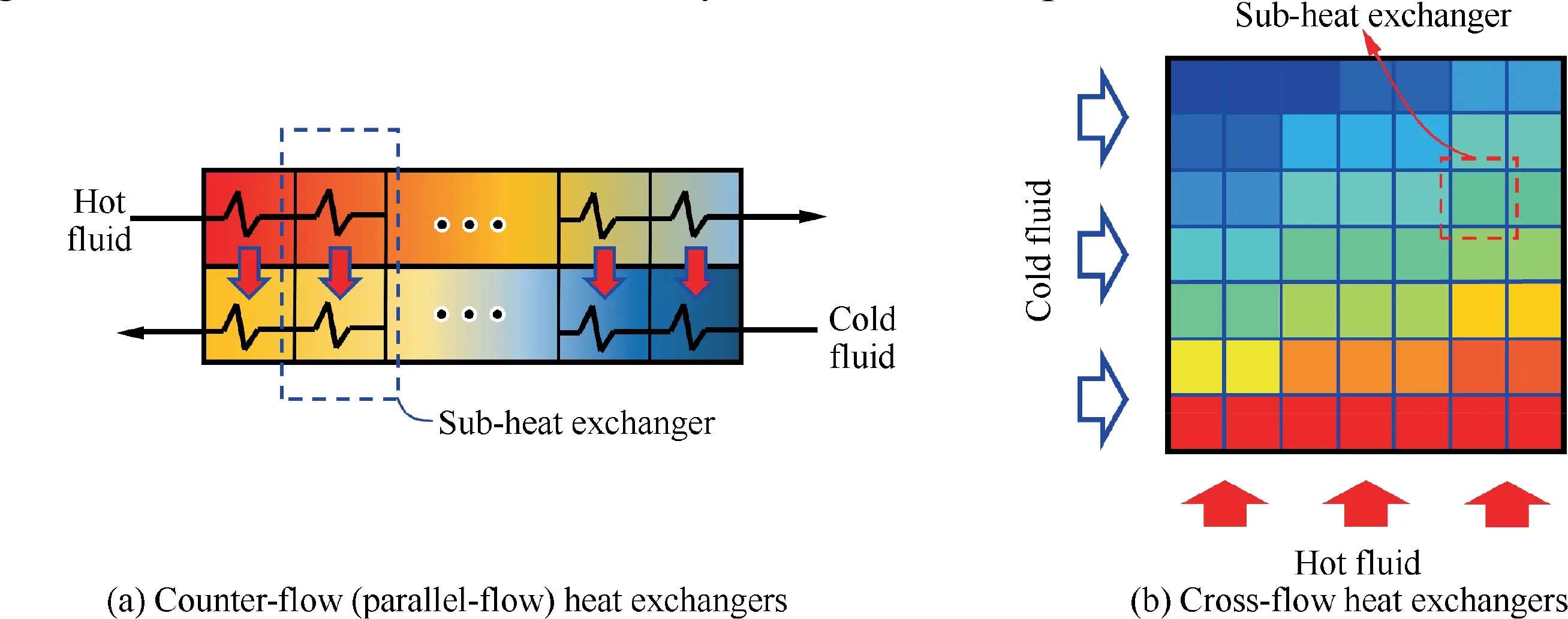
Fig. 2 Conventional segmented design models.
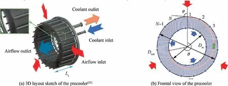
Fig. 3 Geometry of the precooler.
The precooler dimensions are characterized by outer diameter D, inner diameter Dand axial length L. There are a total of N rows of microtubes in staggered, which can be seen from the frontal view in Fig. 3(b). However, the number of rows (N) that are crossed by the airflow may not equal N when the spiral angle θ is different from 2π. As for other detailed structure parameters, such as the pitches (transversal pitch P, longitudinal pitch Pand diagonal pitch P) and diameters (outer diameter dand inner diameter d) of microtubes, will be illustrated in Section 2.2.
2.2. Refined design method
The refined design method combines the advantages of the 0D iterative design methods and the CFD simulations, which can comprehensively consider the coupling effects of fluid properties variation, actual precooler structure and inlet parameters distortion in the limited time. Therefore, relatively few assumptions are adopted in this method, as follows: (A) heat transfer with surroundings is negligible;(B)there is no longitudinal heat conduction;(C)compressibility effects of airflow are neglected; (D) effects of secondary flow in microtube are also neglected;(E)thermal parameters are evenly distributed along the axial direction of the precooler. It is noted that axial nonuniformities of airflow can be significantly improvedand thereby the non-uniform airflow in circumferential direction is the main emphasis in this paper.
2.2.1. New discretization criterion
The precooler in which two fluids flow non-parallel to each other in opposite directions is quite different from traditional counter-flow heat exchangers with the regular shape, thus a new discretization criterion is proposed to exactly capture the multi-parameter variations.
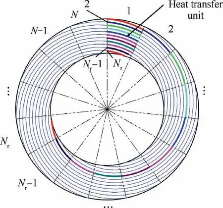
Fig. 4 Definition process of the heat transfer unit.
As shown in Fig. 4, N identical fan-shaped computational domains are divided from a precooler with the assumed structure. Meanwhile, a complete microtube is discretized into Nsub-microtubes. Without inlet parameters distortion, local flow and heat transfer characteristics are the same in each fan-shaped domain due to the periodic condition. Therefore,Nsub-microtubes belonging to the whole microtube can be moved to the same computational domain. With this new discretization criterion, the connected thermal boundary conditions and flow fields on both sides between adjacent sub-microtubes in the combined fan-shaped domain can be strictly guaranteed.Hence,a 2D heat exchange process(radial and circumferential direction) is simplified to 1D one (radial direction). As for the precooler design accounting for the effects of non-uniform airflow, the discretization criterion is similar and will be detailed in Section 2.2.3 by combining with the 2D segmented model.
One can find that in the axial (Z) direction, the indivisible thickness of a precooler can be reduced to Palso owing to the periodic condition. Therefore, based on the partitioned computational domain, a heat transfer unit consisting of two columns of semicircular tubes and one column of circular tubes is defined as shown in Fig. 5. There are Nsubmicrotubes in all and the sum of their lengths is given by:
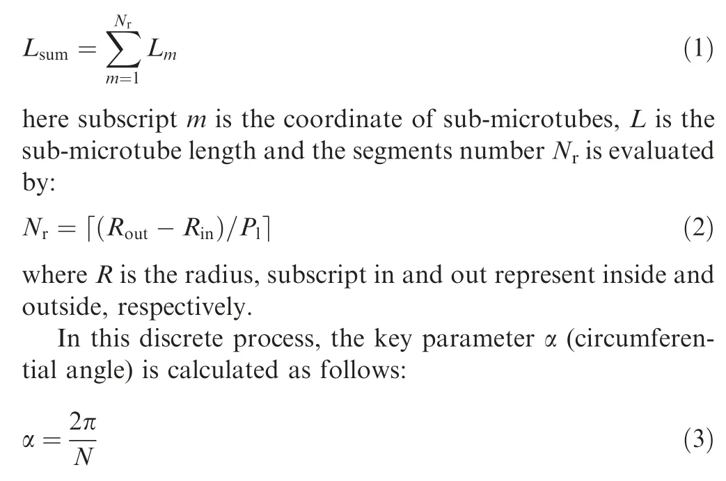
The heat transfer behavior shown in Fig.5(b)indicates that the same supercritical pressure coolant is heated by hightemperature airflow multiple times during the heat exchange process. Consequently, it is reasonable to assume that the 1D counter-flow heat transfer is performed. Dissimilar to the existing discretization criteria, the number of segments in this new criterion is not optional but determined by the arrangement of microtubes. Furthermore, the geometry of the precooler must be set before discretization to accurately obtain the structure parameters.
2.2.2. 1D segmented model
As was stated in Section 2.2.1, the fan-shaped computational domain designated as heat transfer unit can be brought out to facilitate the design scheme when the airflow is uniform.On this basis, a 1D segmented model consisting of Nsubprecoolers is proposed, as revealed in Fig. 6(a). Note that the red borders, which locate in the middle of adjacent submicrotubes, represent hypothetical boundaries of these subprecoolers. During heat transfer process, the hot air flows through No.1 to No.Nsub-precooler in sequence and coolant is just the opposite. Then, the parameter variations in each sub-precooler are within tolerance,such that the overall design parameters of sub-precoolers represent the detailed design parameters of the whole precooler.
Take the No.m sub-precooler as an example, 1D temperature and pressure fields of the airflow can be expressed as:
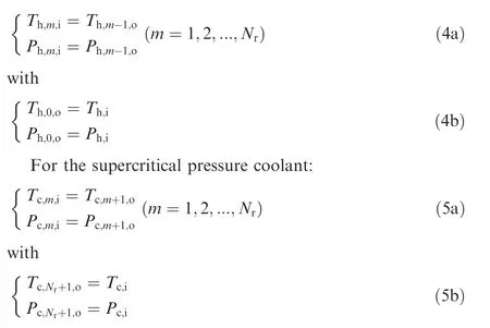
here subscript h,c,i and o represent hot air,coolant,inlet and outlet, respectively. As for the mass flow rates of airflow and coolant in this model, both of them are constants along with their respective flow directions.
Fig. 6(b) displays two types of sub-precoolers: one with a complete sub-microtube and the other with two semicircular sub-microtubes.It is valid to believe that the adjacent semicircular sub-precoolers absorb identical thermal energy due to the same size and symmetrical flow field.However,the heat transfer rates Q-,Qand Qare not equivalent because of the different heat transfer surface area, mean temperature difference and Heat Transfer Coefficient (HTC) among these subprecoolers.
2.2.3. 2D segmented model
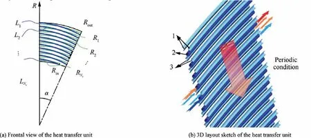
Fig. 5 Heat transfer unit.
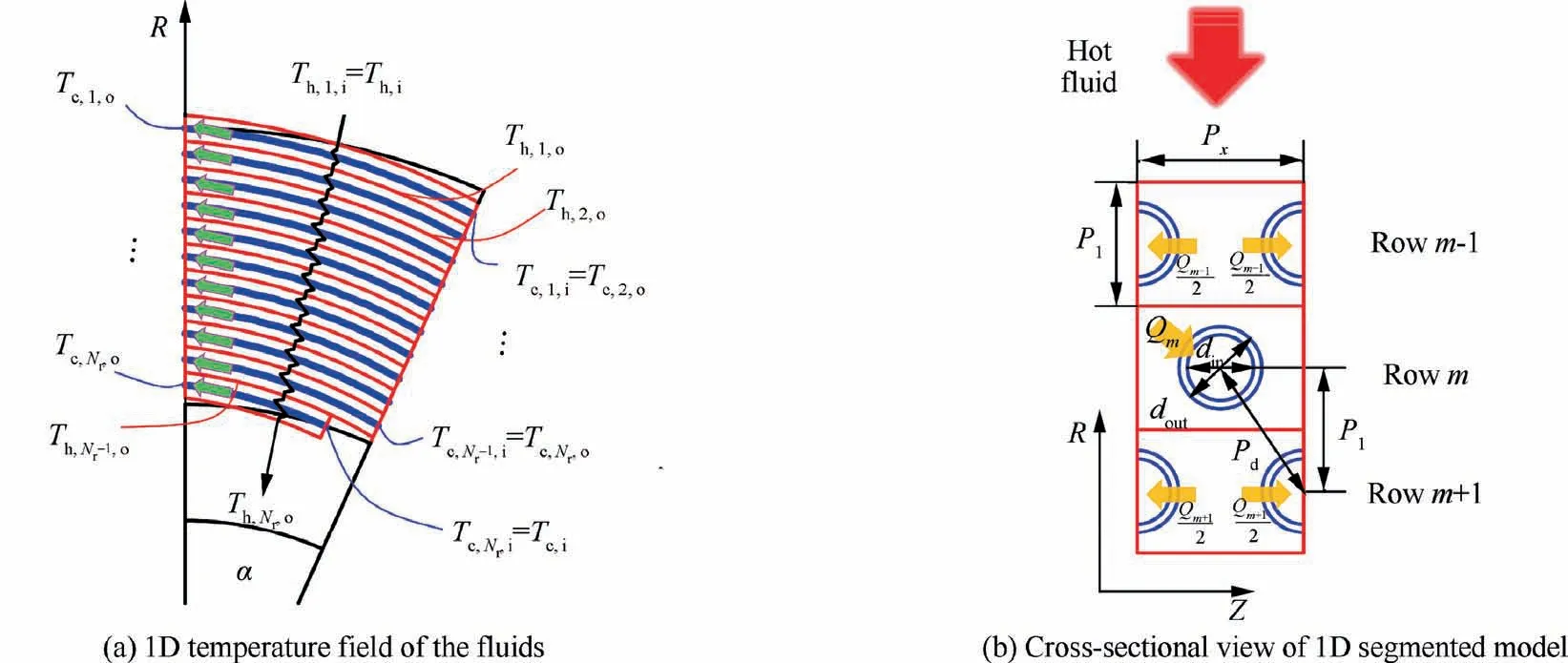
Fig. 6 1D segmented model.
The temperature and mass flow rate of airflow are commonly non-uniform under the real operating conditions of precoolers,and it is also essential to clarify the influence of heat transfer on the thermal parameters distortion due to the negative impacts of the latter on compressors operation.Therefore,considering the inflow non-uniformity and its variation during the thermal design is necessary to accurately estimate the precooler performance.
Owing to the considerable impact of the circumferential inflow parameter distortion, the consistency among different heat transfer units is disrupted. Therefore, a 2D segmented model is developed to solve this problem, as plotted in Fig. 7. It is clear that the same discretization criterion as the 1D segmented model is adopted, but N heat transfer units along circumferential direction are required. There are a total of Nsub-precoolers in each heat transfer unit,then a piece of precooler is divided into N × Nsub-precoolers.
For non-uniform temperature inlet conditions, the dominant temperature gradient is between hot and cold fluids,and the airflow is still not mixed among adjacent heat transfer units.Therefore,the connected boundary conditions of the airflow in the No.(n,m) sub-precooler can be written as:

with

where ˙mis the mass flow rate of the airflow in a subprecooler, subscript n is also the coordinate.
For non-uniform mass flow rate inlet condition, the airflow rate would be redistributed circumferentially after flowing through each row of the sub-precoolers. Therefore,the airflow inlet boundary conditions in the next subprecooler are no longer the outlet parameters in the previous sub-precooler, but the mixed parameters. For example,in the No.(n,m - 1) sub-precooler, ˙mfrom inlet to outlet remains fixed, but ˙mnot equals ˙mdue to the momentum and mass transports among the No.(n-1,m-1), (n,m-1) and (n+1,m-1) sub-precoolers. Thus,the mass flow rate in the No.(n,m) sub-precooler is calculated by:

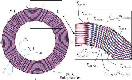
Fig. 7 2D segmented model.
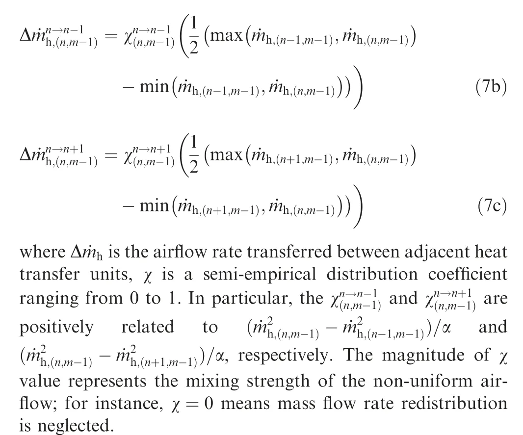
As for the inlet pressure of airflow in the No.(n,m) subprecooler, it equals the mixed pressure leaving the No.(n,m-1) sub-precooler. Besides, due to the low circumferential pressure gradient, the mixed pressure is assumed to be equal to the outlet pressure in the No.(n,m-1) sub-precooler. Thus,P=Pstill holds under this condition.
The inlet temperature is evaluated at mass flow average enthalpy of the mixed airflow to ensure the conservation of energy, which can be obtained from:
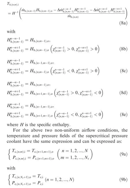
In addition, each heat transfer unit is connected to form a ring shape, resulting in the special n-coordinate association rules at the heat transfer units numbered 1 and N. That is,the No.(N+1,m) sub-precooler represents the No.(1,m) subprecooler. From Eqs. (6)–(9), it is seen that both the m- and n-coordinates may affect the parameter changes of the airflow and coolant, constituting the crucial distinction between the proposed 2D segmented model and the ordinary segmented models for cross- and counter-flow heat exchangers as presented in Fig. 2.
2.2.4. Thermal design of each sub-precooler
2.2.4.1. Heat transfer.
Technically, the thermal design of any sub-precooler in the aforementioned 1D and 2D segmented models is the same except for the designation indices. Hence, the No.m subprecooler in the 1D segmented model is selected as an example for simplicity, and the energy conservation equation is written as:
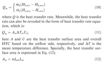
Due to the characteristics of the Archimedes spiral, each sub-precooler has the same passage length along with airflow direction, which is P. However, the corresponding lengths on the cold side Ldecrease from Lto Lowing to the contracted flow area of hot air.In polar coordinates,the equation of Archimedes spiral can be expressed as follows:
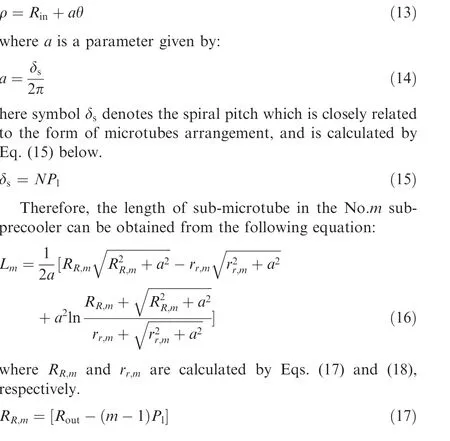
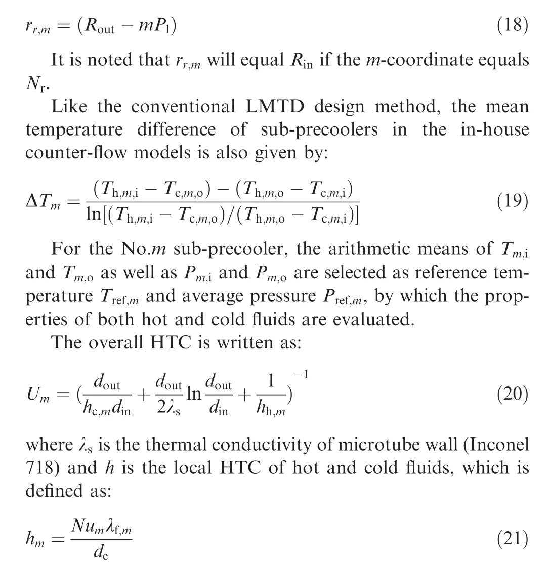
where Nu is the Nusselt number,λis the thermal conductivity of fluids, and dis the equivalent diameter.
Due to the high design accuracy requirement,it is necessary to choose the appropriate Nusselt number correlations. Some traditional correlations on the heat transfer from tubes in cross-flow are shown in Fig.8(i.e.,Zukauskas,Khan et al.,Kays and London,and Colburn.It is found that the apparent difference among these correlations exists even in the same arrangement of tubes in a bank. In the present work, the heat transfer characteristics of cross-flow presented by Kays and Londonis adopted for airflow because of its widespread application in the precooler design.

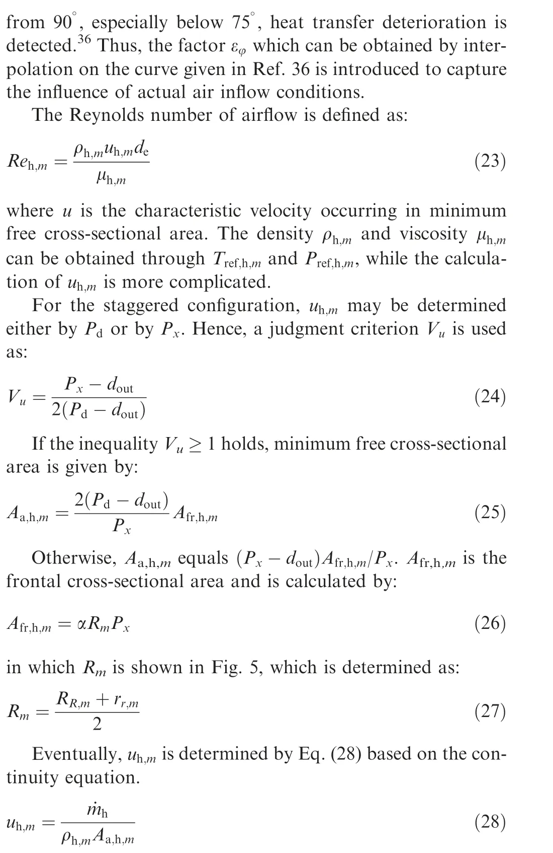
here Cis a factor related to the microtubes arrangement and εis a heat transfer correction factor. The Reynolds number range of Eq.(22)is 300 to 15000,which covers the operational range of the used precooler.Note that the adopted correlation Nuis reasonable only when φ = 90holds. If φ is away
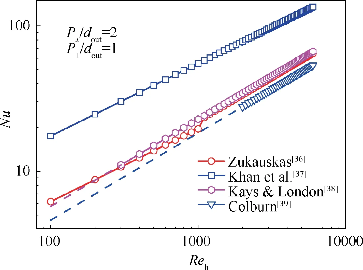
Fig. 8 Comparison of different Nusselt number correlations for external flow.
The supercritical pressure fluid is a promising coolant due to its superior heat transfer performance and low pressure loss.However, the drastic properties variation of coolant significantly reduces the prediction accuracy of Nusselt number correlations for conventional fluids. Thus, an empirical equation for supercritical fluids heat transfer proposed by Jacksonis supplemented in this study and then validated by an experimental study.
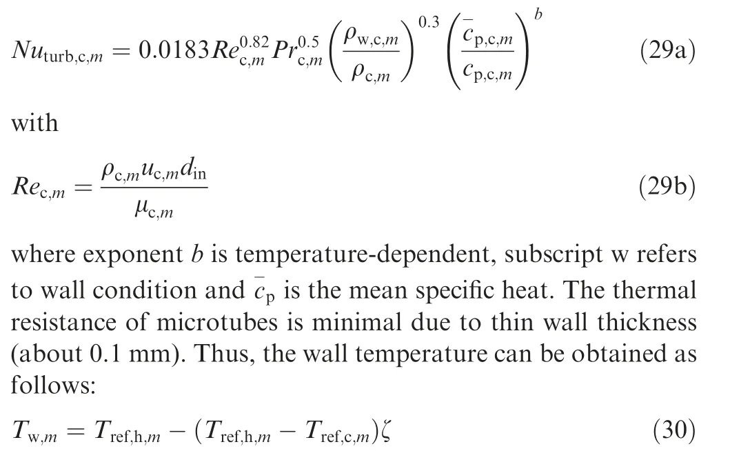
where ζ represents the relative heat transfer capacity of the coolant:
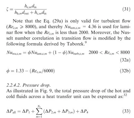
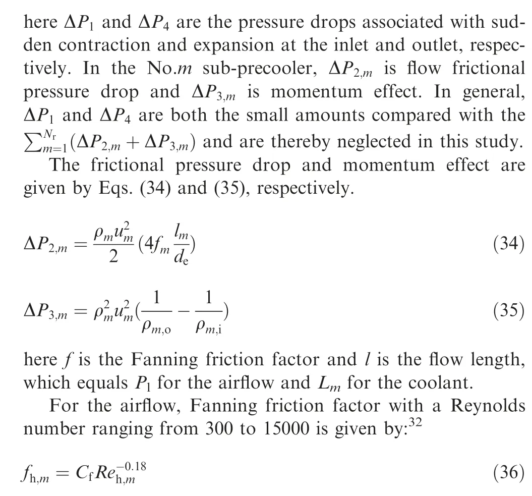
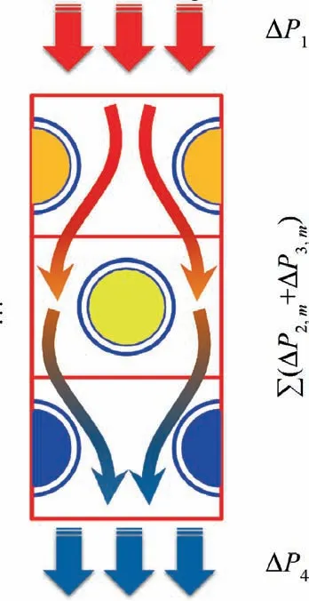
Fig. 9 Components of total pressure drop across the heat transfer unit.
where Cis also a factor related to the microtubes arrangement.
For the internal flow, the flow characteristic of fluids in smooth tubes presented by Churchillis employed in this paper due to its high effectiveness in the whole range of Reynolds number.

where Kand Kare both Re-dependent.
2.2.5. Calculation procedure
A flow-chart shown in Fig. 10(a) helps understand the design procedure of the 1D segmented model better. After getting design requirement parameters,including mass flow rates,inlet temperatures and pressures,and outlet temperatures,designers should first guess precooler geometry D, D, L, N and the coolant outlet pressure P. Via setting detailed structure parameters P, P, dand d, a heat transfer unit can then be acquired and discretized into numerous sub-precoolers immediately.
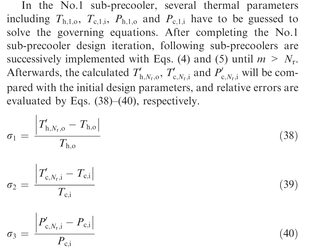
If any value of σ(k=1;2;3)is greater than a set value σ(0.001), the precooler geometry and Phave to be renewed until the convergence condition is reached. Completing the above iterations only means that the governing equations get convergent results. However, the total pressure drop of hot and cold fluids respectively should be lower than tolerance pressure drop (ΔP). Otherwise, the iterations would carry on.
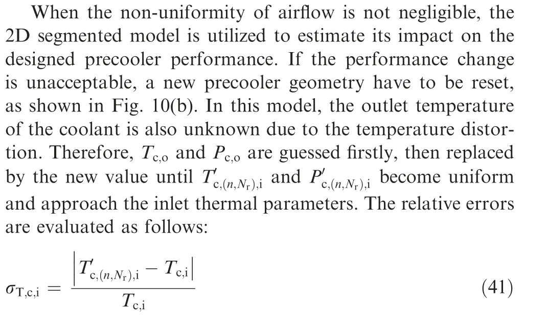
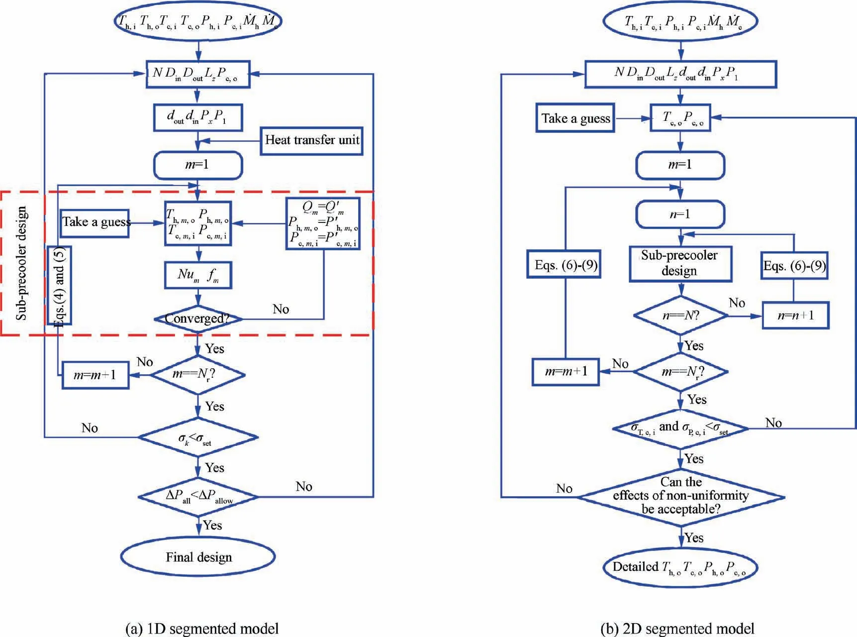
Fig. 10 Flow-chart of the in-house segmented models.

The iterations in each sub-precooler are consistent with the 1D segmented model, while the connections Eqs. (6)–(9)between the sub-precoolers should be handled carefully.
2.3. Validation analysis
As the cornerstone of this refined design method is several published empirical correlations, it is necessary to confirm their validity in precoolers operating condition. Although Eqs. (22), (36) and (37) have been validated by many researchers,the Nusselt number predictions of supercritical pressure coolant are barely involved in previous studies,especially for the promising hydrocarbon fuel coolant. Therefore, heat transfer experiments of the supercritical aviation kerosene (typical hydrocarbon fuel) were carried out to verify the adopted Jackson correlation. Moreover, the validation of the proposed models was also performed.
2.3.1. Correlation validation of supercritical fuel heat transfer
The schematic diagram of the supercritical heat transfer experimental system is displayed in Fig. 11. In this experiment, the kerosene was first pumped by a diaphragm pump (YB3-80M2-4, 6.7 MPa, 0–80 L/h) up to a certain pressure. After measurement by a Coriolis mass flow meter (DFM1-1-B, 0–20 kg/h, 0.15%), the kerosene flowed into the preheating section and was heated to the required inlet parameters for the experimental section. Afterwards, a low-voltage directcurrent power(DC power)(JP50300D,0.5%)was used to heat the experimental section to simulate the constant heat flux boundary condition. Note that the heating power was controlled to ensure the outlet temperature is less than cracking temperature.After heat exchange,the hot kerosene was cooled to room temperature and discharged to a fuel collector.
The experimental section is a stainless steel U-tube with an inner diameter of 1.5 mm and a bend diameter of 150 mm.This microtube is 1036 mm long with two adiabatic sections of each 150 mm. The outer wall temperature of the heating part was monitored by skin K-type thermocouples (±1.5 K), while the inlet and outlet temperature and inlet pressure at the experimental section were measured by armored thermocouples(±1.5 K) and a pressure gauge transducer, respectively, as shown in Fig. 11.
Considering the measurement errors of independent variables, the uncertainty of the local HTC of supercritical kerosene would be less than 3.65%. In particular, the local HTC along this microtube is defined by:
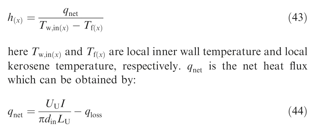
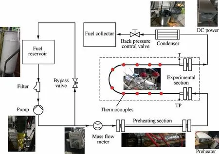
Fig. 11 Schematic diagram of the supercritical heat transfer experimental system.
where Lis the heating length of microtube,Uis the voltage,I is the current,qis the heat loss and fitted from experimental data. Tis attained from the measured outer wall temperature through one-dimensional cylindrical heat conduction equation.
Furthermore, Twas calculated by the following equation:

here Qis the heating power from the entrance of heating section to the point x and His the specific enthalpy of the kerosene at entrance.
The local Reynolds number, inner wall and kerosene temperature distributions along the microtube at 3 MPa system pressure, 386 K inlet temperature, 1430 kg/ms mass flux and 624 kW/mheat flux are shown in Fig. 12(a). It is found that Tdisplays an unexpected variation due to the complex heat transfer characteristics, and the Reynolds number of kerosene increases drastically when it approaches to pseudocritical temperature(T).However,the local HTC fails to rise as expected by Gnielinski empirical equation,as shown in Fig. 12(b). This is mainly because the conventional Nusselt number correlations are unable to consider the radial variation in properties of supercritical fluids. However, due to the high heat flux, the difference in Tand Tis significant in the precooler, and the radial parameters gradient cannot be ignored.
By introducing correction terms, the Jackson equation matches the experimental data with slight overestimation.But its prediction errors are acceptable for engineering design compared to the conventional Nusselt number correlations.Moreover, an important feature has been exposed in this experiment, which is the maximum inner wall temperature is reached at the outlet of the bend section. This should be carefully considered for serpentine precooler design (e.g., the precoolers used in ATREX engine), especially at a high flight Mach number.
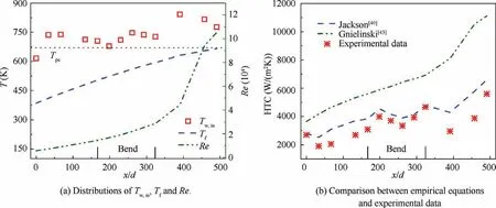
Fig. 12 Correlation validation of the supercritical fuel heat transfer.
2.3.2. Model validation of the heat transfer unit
A scaled precooler named JMHX with up to 3000 m/mcompactness was manufactured and tested at high heat flux and temperature variations in Ref. 42. This small precooler is a cross-flow shell-and-tube heat exchanger with thin microtubes(0.38 mm) and fully similar to a heat transfer unit of the fullscale precooler in Fig.3(a).The high-temperature nitrogen gas crosses the staggered microtubes while the high-pressure nitrogen or helium flowing in smooth passages.
The experimental data obtained from the JMHX are referred to validate the 1D segmented model,while the 2D segmented model is validated by giving the identical entrance conditions. Under the same inlet conditions (both design point and twice the design point), the temperature variations of the cryogenic nitrogen calculated by the proposed method are compared with the experimental data in Fig.13.The relative error obtained by the 1D segmented model is less than 8.8%except for the precooler inlet and outlet regions.The influences of these regions on the full-scale precooler are negligible because of the large number of tube rows. Furthermore, the predicted total heat transfer rate of this small precooler at the design point has a discrepancy of 7.3%, which satisfies the forecasting requirement.By evidence, the adopted correlations are reliable and the LMTD design method is still effective in sub-precooler design.Furthermore,high accuracy of the proposed method is demonstrated by comparison.
3. Case study and discussion
As a reminder, a refined design method for advanced precoolers with consideration of multi-parameter variations based on low-dimensional analysis is proposed in this paper. Specifically, a hydrocarbon fuel precooler is designed and analyzed as a demonstration due to its promising application potential in hypersonic precooled engines and precooled-TBCC engines.It is found that the experimental and discrete properties of the aviation kerosene are not conducive to the iterative design. Therefore, another alternative hydrocarbon fuel named n-decane,which has a similar variation in thermophysical properties with the aviation kerosene(Fig.1),is selected as the coolant.Its properties are obtained by using the software REFPROP.Noting that the proposed design method has no restriction on the type of the coolant.
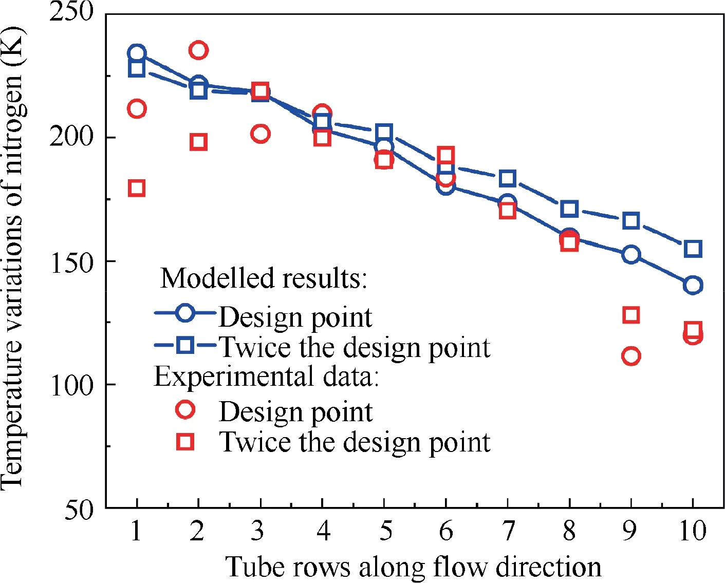
Fig. 13 Comparison between predictions and experimental data.42
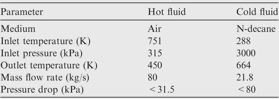
Table 1 Initial design parameters of the precooler.
In this case,the hydrocarbon fuel precooler needs to ensure that a conventional turbojet efficiently operates at Mach 3.5 flight condition. Moreover, the detailed initial design parameters are listed in Table 1.
According to the constraints shown in Table 1, a qualified precooler, whose compactness and power/weight ratio are about 1570 m/mand 90 kW/kg respectively, is designed by the proposed 1D segmented model. The structure parameters of this fuel precooler are listed in Table 2.
3.1. Design analysis of the precooler with uniform airflow
The heat transfer performance of the designed precooler is plotted in Fig. 14. It is found that the non-linear variations of local temperatures and heat transfer rate are completely captured by the proposed method (Fig. 14(a)). In this case,the temperature drop of the airflow over precooler depth is 301 K,while the majority of thermal energy exchanged is concentrated in the airflow inlet region. Therefore, Fig. 14(b) displays the distributions of local overall HTC, heat transfer surface area and mean temperature difference of each subprecooler to explain the non-uniform heat transfer rate. Due to the contraction of precooler cross-sectional area, the heat transfer surface area gradually decreases along with the airflow direction. While the overall HTC exhibits more dramatic changes and is reduced by 71.1%, mainly because of the thermophysical properties variation. Thus, despite the low mean temperature difference, the heat transfer performance of subprecoolers with smaller index number is superior.
To further demonstrate the capability of the refined design method, the varying thermophysical properties of both fluids along with the 1D model are shown in Fig.15.During the heat exchange, the variations of airflow properties are relatively weak, i.e., 51.1% increase in density, 5.9%, 32.1% and 29.4% decrease in c, thermal conductivity and dynamic viscosity, respectively. Correspondingly, the viscosity, density and thermal conductivity of the hydrocarbon fuel are dramatically reduced by 97.9%,78.2%and 54.4%with the process of absorbing heat energy.Furthermore,the maximum proportion increase of cis 179.0% at position m=4, which significantlystrengthens the heat absorption capacity of the coolant. It is knew that the flow and heat transfer characteristics of fluids are not only related to thermophysical properties, but also to flow regime and channel size. Hence, the local distributions of Reynolds number and flow area of both air and coolant are illustrated in Fig. 16.

Table 2 Structure parameters of designed precooler.
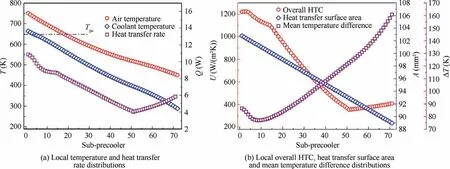
Fig. 14 Heat transfer performance of the precooler.
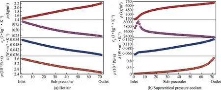
Fig. 15 Thermophysical property variations of both air and coolant along with the precooler.
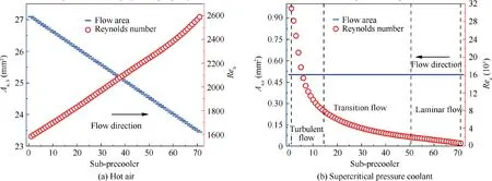
Fig. 16 Local distributions of flow area and Reynolds number of both air and coolant.
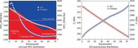
Fig. 17 Local flow and heat transfer characteristics of both fluids along with the precooler.
Due to the ring structure of precoolers,the flow area of hot air in a heat transfer unit is naturally diminished by 13.5%.Moreover, the airflow Reynolds number almost linearly increases along with its flow direction because of the coupling effect of the decreasing flow area and viscosity.The maximum and minimum of the Reynolds number are 2589.1 and 1581.9,respectively. That means the heat transfer of airflow is only in the mixed flow regime. As for the supercritical pressure coolant, the flow area is constant. While the Reynolds number shows a rapid increase along with the flow direction,especially near the pseudo-critical temperature of 648 K. It means that the supercritical coolant undergoes laminar,transition and turbulent flow from inlet to outlet, which will evidently affect the local performance of the precooler. This further proves that the 0D heat exchanger design method is not appropriative.
Eventually, the local HTC distributions of both air and coolant are compared to clarify the drastic changes of the overall HTC, as shown in Fig. 17(a). Despite the increasing Reynolds number, the heat transfer performance of airflow has deteriorated. Based on the Eq. (21) and Fig. 8, it is concluded that the thermal conductivity is the dominant heat transfer variable for airflow in this case.Moreover,the local HTC profile of the coolant is more complex. It begins with a quite low value while the coolant flows in viscosity dominant laminar regime. Yet a sharp increment of heat transfer performance occurs when the flow enters turbulence.Afterward,the second enhancement is produced by the supercritical heat transfer with the maximum HTC reaching about 7598.9 W/mK.Therefore, the overall HTC variation mainly originates from the flow transition of the coolant.
In addition,the proportion variations of thermal resistance of each fluid are also given in stacked area plots (Fig. 17(a)).Contrasting with helium and hydrogen precoolers,the heat transfer performance of airflow is not the poorest overall and its thermal resistance is less than that of hydrocarbon fuel in 59.2% of the sub-precoolers. The underlying reason is the high viscosity of hydrocarbon fuel coolant, causing 80.3% of the supercritical pressure flow to remain laminar and in transition.Furthermore,local pressure distributions have been illustrated in Fig. 17(b). One can see that the pressure drop of airflow in each sub-precooler is approximately uniform, leading to a linear distribution of pressure. The pressure profile of coolant is more complex but its pressure drop is much smaller than the high inlet pressure.
3.2. Effects of circumferential temperature distortion
The interaction between airflow circumferential temperature distortion and precooler performance is highlighted in this section using the 2D segmented model. For convenience, a reduced scale precooler with the same average air inlet temperature(751 K)and temperature drop(301 K)is adopted.In this case,the mass flow rate of airflow and coolant become 0.4 kg/s and 0.31 kg/s, respectively. The coolant inlet temperature is 350 K. The linear inlet temperature distortion of the airflow is shown in Fig.18.Moreover,the geometry of this scaled precooler are characterized by D=195 mm, D=120 mm,L=39 mm, N=24, N=38 and α=0.262. Other structural parameters are the same as those in Table 2.
Thanks to the specific heat exchange features, the same coolant can absorb heat energy from the hot air with different m- and n-coordinates. Besides that, the airflow temperature is limited by coolant inlet temperature due to counter-flow arrangement. Thus, the circumferential temperature nonuniformity of hot air is greatly weakened as plotted in Fig.18.To clarify the effects of temperature distortion on precooler performance, the difference in the local heat transfer rate of the scaled precooler between uniform and nonuniform airflow are illustrated in Fig. 19(a).
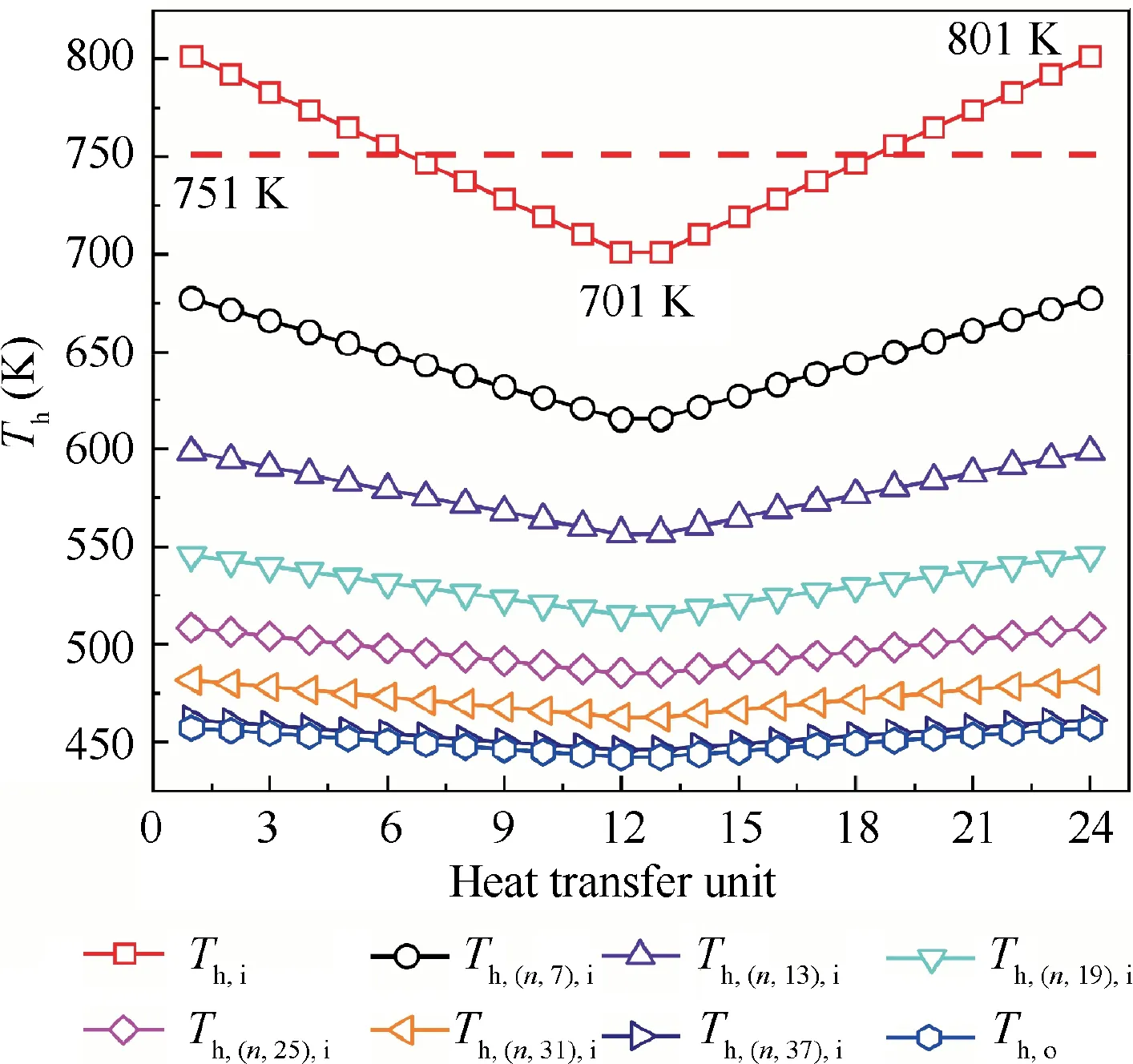
Fig. 18 Variations of air temperature non-uniformity.

Fig. 19 Effects of airflow temperature distortion on precooler local performance.
As revealed in Fig. 19(a), the performance enhancement area (Q-Q>0) due to airflow temperature distortion is concentrated at the heat transfer units with high inlet temperature. The maximum increased heat exchange of the sub-precooler, 4.14 W, occurs at position (n,m)=(1,1),while the maximum performance deterioration is -4.00 W at position (n,m)=(13,1). As for the whole precooler, total heat transfer rate is almost unchanged. To explain the above two different effects, the percentage variations of the local overall HTC and LMTD are shown in Fig. 19(b) and (c)respectively. It can be found that the local overall HTC has little deviation from the uniform condition compared with the LMTD. So it is obvious that the changing of LMTD is the dominant factor in this particular situation,which alters the local performance of the precooler. Furthermore, due to the almost symmetrical distributions of both local overall HTC and LMTD variations, the effect on the overall performance is thereby little.
4. Conclusions
As the actual operating condition of advanced precoolers disqualifies the existing 0D heat exchanger design methods, a refined design method considering multi-parameter variations based on low-dimensional analysis was proposed in this paper to conveniently provide the practical engineering design. The following conclusions are drawn:
(1) These novel 1D and 2D segmented models permit the prediction of precooler local performance. The effects of multi-parameter variations, including fluid thermophysical properties, flow area and thermal parameters distortion, on the local performance were confirmed to be non-negligible.
(2) The hydrocarbon fuel coolant undergoes laminar, transition and turbulent flow due to the drastically reduced viscosity in a precooler with microtubes, which leads to its thermal resistance is higher than that of airflow in 59.2% of the sub-precoolers. Therefore, more heat transfer enhancement technology is suggested.
(3) The circumferential temperature distortion of airflow is greatly weakened by the heat transfer. Referring to the second case study,the total heat transfer rate was almost unchanged and the opposite is observed for the local performance.This feature is mainly due to the variations of local mean temperature difference.
The authors declare that they have no known competing financial interests or personal relationships that could have appeared to influence the work reported in this paper.
This study was co-supported by the Specialized Research Foundation of Civil Aircraft, China (MJ-2016-D-35) and the Advanced Jet Propulsion Creativity Center, AEAC, China(HKCX2019-01-004).
 Chinese Journal of Aeronautics2022年3期
- Chinese Journal of Aeronautics的其它文章
- Flow response hysteresis of throat regulation process of a two-dimensional mixed-compression supersonic inlet
- A step parameters prediction model based on transfer process neural network for exhaust gas temperature estimation after washing aero-engines
- Recent progress in flexible supporting technology for aerospace thin-walled parts: A review
- Numerical investigation of dynamic stall suppression of rotor airfoil via improved co-flow jet
- Interaction formulae for buckling and failure of orthotropic plates under combined axial compression/tension and shear
- Solar-tracking methodology based on refraction-polarization in Snell’s window for underwater navigation
