Numerical investigation of dynamic stall suppression of rotor airfoil via improved co-flow jet
Jiqi LIU, Rongqin CHEN ,*, Yncheng YOU , Zheyu SHI
a School of Aerospace Engineering, Xiamen University, Xiamen 361005, China
b Rotor Aerodynamics Key Laboratory, China Aerodynamics Research and Development Center, Mianyang 621000, China
KEYWORDS Co-flow jet;Dynamic stall;Flow control;Parameter analysis;Rotor airfoil
Abstract The decrease in aerodynamic performance caused by the shock-induced dynamic stall of an advancing blade and the dynamic stall of a retreating blade at low speed and high angles of attack limits the flight speed of a helicopter. However, little research has been carried on the flow control methods employed to suppress both the dynamic stall induced by a shock wave and the dynamic stall occurring at high angles of attack. The dynamic stall suppression of a rotor airfoil by Co-Flow Jet (CFJ) is numerically investigated in this work. The flowfield of the airfoil is simulated by solving Reynolds Averaged Navier-Stokes equations based on the sliding mesh technique.Firstly, to improve the effect of a traditional CFJ on suppressing rotor airfoil shock-induced dynamic stall, an improved CFJ—a CFJ-sloping slot is proposed. Research shows that the CFJsloping slot suppresses the shock-induced dynamic stall more effectively than a traditional CFJ.Moreover, the improved CFJ can also suppress the dynamic stall of rotor airfoil at low speed and high angles of attack. The improved CFJ proposed in this paper is an effective flow control method that simultaneously suppresses the dynamic stall of the advancing and retreating blades.The mechanism of the improved CFJ in suppressing the dynamic stall of the rotor airfoil is studied,and a comparison is made between the improved CFJ and the traditional CFJ in terms of dynamic stall suppression at high and low speed. Finally, the effect of improved CFJ parameters (the jet momentum coefficient,the position of the injection/suction slot,and the size of the injection/suction slot) on shock-induced dynamic stall suppression is analyzed.
1. Introduction
Helicopters have the advantages of vertical take-off and landing, high mobility, and hovering in the air, which are widely used in military and civilian fields. However, the low speed of conventional helicopters greatly affects their application range. High speed has become a non-negotiable quality in the new generation of helicopter technology, so research on high-speed technologies is very important for economic benefits and military strategic value. The limitation in the flight speed of the helicopter is related to the characteristics of the airflow around the rotor. When the helicopter flies forward at high speed, the tip speed of the advancing side is greater than that of the retreating side. The shock wave appears on the advancing side and induces separation of airflow on the suction surface of the blade,under the interaction of the shock wave and boundary layer, causing a dynamic stall. Additionally, because the blade on the advancing side works at a high Angle of Attack(AoA),it may cause considerable airflow separation, and even dynamic stall. These phenomena lead to a noticeable increase in the drag and power consumption of the rotor, which limits the flight speed of the helicopter.Therefore, how to suppress the dynamic stall induced by the shock wave on the advancing side and the dynamic stall on the retreating side at large angles of attack is significant in improving the aerodynamic performance of the helicopter.
Control methods for the shock-induced stall of the rotor blades mainly include optimizing the tip shape, e.g., using backward-sweep, forward-sweep, and parabolic shapeswhich decompose the flow velocity and delay the shock wave.These methods are essentially passive control methods, but they only have a better control effect in the particular conditions. Szulc et al.proposed a method of stalling a cavity covered by a perforated plate near the shock wave of the rotor.The airflow behind the shock wave flows to the wavefront through the perforated plate, which automatically adjusts the pressure before and after the shock wave,decreasing the intensity of the shock wave. However, this method induces backflow of the boundary layer, and the viscous resistance is greatly increased. In most cases, the viscosity loss is greater than or equal to the gain in wave-resistance reduction.Compared with passive control methods, active control methods have the advantage of being able to be applied at the required time and location, and can be actively adjusted, making them superior. Scholars have proposed an active control method that uses synthetic jets,which can affect shock-boundary layer interaction and suppress boundary layer separation.However, synthetic jets interact weakly with the mainstream, and this control effect and mechanism need further study. Active control methods involved in the dynamic stall on the retreating side at high AoA mainly include variable droop leadingedgeand active trailing-edge flaps. Although these methods are effective for suppressing the dynamic stall, the mechanical structure of them is complicated, compromising the stability of the rotor, meaning the mechanism consumes more power. In summary, the dynamic stall of the rotor has not been well resolved,especially shock-induced dynamic stall.Moreover,there is still a lack of control methods that suppress both dynamic stall induced by the shock wave and dynamic stall at high AoA. There is an urgent need, therefore, to develop an effective control method to improve rotor aerodynamic performance.
The Co-Flow Jet (CFJ) active flow control method was developed by Zha et al..The CFJ airfoil opens an injection slot and a suction slot near the leading-edge and trailing-edge of the airfoil, respectively. A micro-pump and pipes are arranged inside the rotor to suck in air and deliver it to the injection slot. Since the injection volume equals the suction volume,the CFJ is an efficient active flow control method that does not need an additional air source. A high-energy tangential jet is injected in the same direction as the main flow near the leading-edge of the airfoil,which blends with the turbulent shear layer to enhance its ability to resist an adverse pressure gradient.Research has proved that this technique can suppress flow separation, improve stall characteristics, significantly increase the lift-to-drag ratio, and has high energy utilization.With the development of motor miniaturization and highpower technology, this technique has broad application prospects. Compared with the Circulation Control (CC) airfoil, the leading or trailing edge of the CFJ airfoil is not blunt, which reduces drag in flight. Compared with synthetic jets, the CFJ controls jet intensity more strongly. The latest research shows that CFJ can also improve the aerodynamic performance, lift-to-drag ratio, and lift coefficient of airfoils at transonic speeds. In summary, the CFJ is a potential flow control method that can simultaneously suppress shockinduced dynamic stall on the advancing side at transonic speeds and dynamic stall on the retreating side at high AoA.
In this work, the SC1095 rotor airfoil is selected as the research object. First, traditional CFJ suppression of shockinduced dynamic stall is studied. Because of the inherent deficiencies of this type of suppression, a new CFJ method is proposed, which better suppresses shock-induced dynamic stall.Moreover, this work also examines the improved CFJ in the suppression of dynamic stall at low speed and high AoA,showing that the suppression effect is equivalent to that of the traditional CFJ. This verifies that the improved CFJ is an active flow control method that effectively suppresses the shock-induced dynamic stall on the advancing side, and also the dynamic stall on the retreating side at large AoAs. The mechanism of airfoil dynamic stall suppression based on the improved CFJ is then studied. Finally, the effect of the improved CFJ momentum coefficient, the position and size of the injection/suction slot on suppressing the shockinduced dynamic stall of the rotor is investigated.
2. Numerical simulation methods
2.1. Governing equations and mesh method
To simulate the flow field around the rotor airfoil, unsteady Reynolds Averaged Navier-Stokes (RANS) equations are applied in this research,and an integral form of the governing equations are described as:
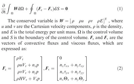
where p is the pressure of airflow, and H is the total enthalpy per unit mass. V= V - V, V is the velocity normal to the surface element dS, Vis the contravariant velocity. nand nare the normal vector components of the control surface. τis the viscous stress term, and Θis the term to describe the heat conduction in the fluid.
The finite-volume methodis employed to discretize the Navier-Stokes (N-S) equations. The central differencing is applied to compute the viscous fluxes, the inviscid fluxes are discretized using the Roe scheme. The temporal discretization is second-order accuracy dual-time stepping. The oneequation Spalart-Allmaras(S-A)turbulence model is applied in this work to close the N-S equations.
The sliding mesh technique is employed in this work to simulate the pitching motion of the rotor airfoil. The computational domain includes two sets of grids: one for the stationary components and another for the airfoil. The information transfer across the interface occurs by interpolation.A pitching motion around the 1/4 chord point can be written as:

where c donates the chord length and Vis the velocity of the free stream.
2.2. CFJ numerical simulation method
As shown in Fig.1,the injection slot is placed near the leadingedge and the suction slot is placed near the trailing-edge on the upper surface of the CFJ airfoil. The airflow is driven by a micro-pump inside the airfoil. The tangential high-speed jet is injected into the main flow,while the same mass flow is withdrawn into the suction slot. A simplified CFJ airfoil model,without pipes and a micro-pump, is employed in this study.To achieve the CFJ, the suitable boundary conditions are employed: the velocity inlet is applied for the injection slot; a no-slip condition is applied for the airfoil surface;the pressure outlet is applied for the suction slot; and the suction slot and injection slot mass flows are well matched by adjusting the boundary conditions.
With the CFJ airfoil, the jet intensity is quantified by a dimensionless parameter,the jet momentum coefficient,which is written as:


Fig. 1 CFJ airfoil.
where ˙m and Vare CFJ injection mass flow rate and the injection jet velocity, respectively. ρis the density of the free stream. And Sdonates the reference area of the airfoil.
3. Numerical method validation
In order to verify the correctness of the numerical simulation method of airfoil dynamic stall under CFJ active control, the calculations of three cases were compared with experimental data.
3.1. Shock-boundary layer interaction validation
To verify the correctness of the simulation method for shock wave-boundary layer interaction in this work,the SC1095 airfoil was subjected to a transonic steady flow of Mach number Ma=0.8 and Reynolds number Re=5.65 × 10at α= 6.2°. Fig. 2 shows the calculated pressure contours map.A comparison of the pressure coefficient (C) distributions for the simulated and experimental dataover the airfoil surface is shown in Fig.3.Clearly,the numerical results agree well with experiment data,thus validating the numerical method in this work.
3.2. Dynamic stall validation
In this section, the oscillation of a NACA 0012 airfoilat Ma=0.283 and Re=3.45 × 10is employed to verify the applicability of the numerical simulation method in this work to dynamic stall.The pitching motion follows Eq.(3),and the mean angle αis 15°, the oscillation amplitude αis 10°,reduced frequency k is 0.151. Fig. 4 shows comparisons of lift coefficient(C)and drag coefficient(C)distributions between calculation and experiment, with an excellent agreement between the two reached using the present numerical method.Hence, this method is considered valid for simulating the dynamic stall of an airfoil.
3.3. CFJ numerical simulation validation
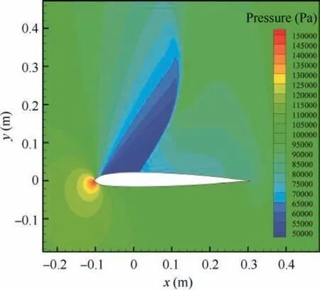
Fig. 2 Pressure contours of SC1095 airfoil.
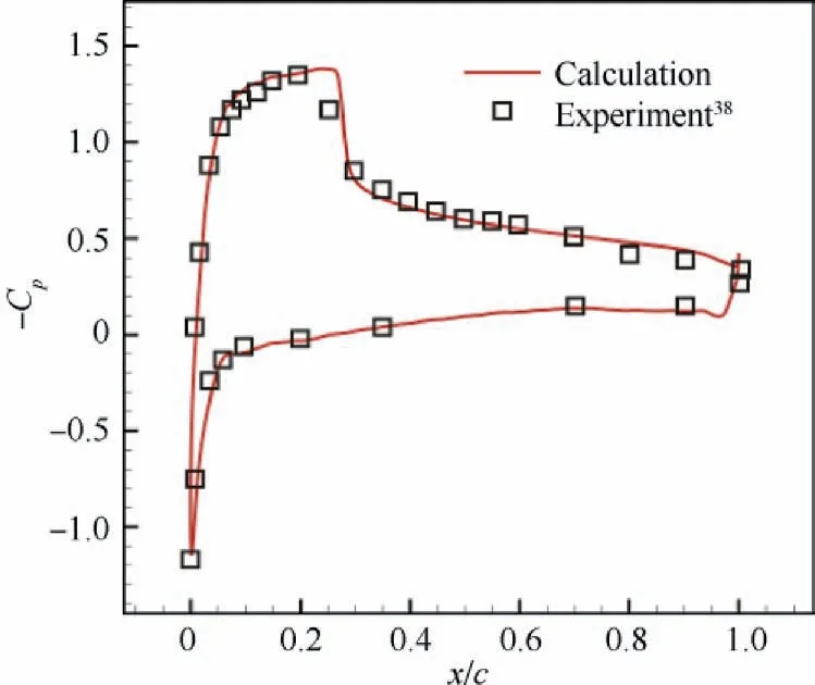
Fig. 3 Pressure coefficient of SC1095 airfoil.
In the third case, a NACA6415 airfoil based on steady CFJ flow control,is to verify the correctness of the CFJ simulation method. The computational conditions are as follows: The Mach number of freestream is 0.3, the Reynolds number is 2.08 × 10, and the jet momentum coefficient C= 0.08.Fig. 5 shows the airfoil lift coefficient and drag coefficient at AoA = 0°, 5°, 10°, 15°, 20°, 25° respectively. The calculations are in good agreement with the results in Ref.,confirming the correctness of the numerical method. The pressure contours and streamlines of the NACA6415 baseline and CFJ airfoil are shown in Fig. 6. Clearly, the flow separation at the trailing-edge is significantly suppressed by the CFJ.
4. Dynamic stall suppression of rotor airfoil based on CFJ
4.1. Shock-induced dynamic stall suppression based on CFJ
The rotor airfoil SC1095 used on the UH-60 Black Hawk USarmy helicopter is selected to study shock-induced dynamic stall suppression based on the CFJ.The calculation conditions are as follows: The Mach number is 0.7 and the Reynolds number is 1.18 × 10. The pitching motion follows Eq. (3),in which the mean angle αand the oscillation amplitude αboth are equal to 4°, and the reduced frequency k is equal to 0.1.
Fig.7 is a sketch of the traditional CFJ airfoil.The slots are designed by translating downward and rotating a portion of the upper surface, which generates a small step, called a‘‘CFJ-stepped slot” in this work. The injection slot is placed at 3.5%c from the leading-edge on the suction face and its size is 0.3%c.The suction slot is placed at 70%c from the leadingedge on the suction face and its size is 0.6%c.
To verify the mesh independency, three different sets of structural mesh (coarse mesh: 9.7 × 10cells, medium mesh:1.6 × 10cells, fine mesh: 2.2 × 10cells) are built for numerical simulation. And the medium mesh around the airfoil is shown in Fig. 8. The thickness of the first cell near the airfoil surface is 4.5 × 10c, and the yis less than 1.0. And yis the dimensionless wall distance which denoted by:

where y is the distance from the wall,uis the friction velocity,and ν is the kinematic viscosity.
Fig. 9 shows the hysteresis loops of lift coefficient with different meshes at the jet momentum coefficient is 0.003. It can be found that the hysteresis loops are closed to each other,which indicates that the mesh is appropriate for calculating.And the medium mesh is employed in the following work.
Fig.10 shows the hysteresis loops of the lift coefficient,drag coefficient,moment coefficient, and lift-to-drag ratio at the jet momentum coefficient is 0.002 and 0.003, respectively. As can be seen from the figures,the lift coefficient of the CFJ-stepped slot airfoil decreases at most AoAs and only slightly increases at high AoAs during the downstroke. The drag coefficient decreases only in the middle of the upstroke, and that of the other AoAs increase.The lift-to-drag ratio(L/D)of the airfoil is almost reduced in the whole process.The moment coefficient(C)has a low degree of fluctuation,but the absolute value of the negative peak value increases. Therefore, the traditional CFJ-stepped slot does not significantly suppress shockinduced dynamic stall at high speed.
In view of the failure of traditional CFJ-stepped slot in suppressing shock-induced dynamic stall, an improved CFJ control scheme is proposed in this paper, CFJ-sloping slot, as shown in Fig. 11. The airfoil profile between the injection slot and the suction slot remains unchanged from the baseline airfoil. A 1%c width injection slot is installed near the airfoil leading-edge, and a 2%c width injection slot is installed near the airfoil trailing-edge.The position and size of the injection/-suction slot are as same as the CFJ-stepped slot airfoil. The mesh parameters are the same as that of CFJ-stepped slot airfoil, and the mesh around the airfoil is shown in Fig. 12.
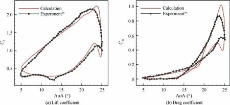
Fig. 4 Comparisons of lift and drag coefficient between calculation and experiment.
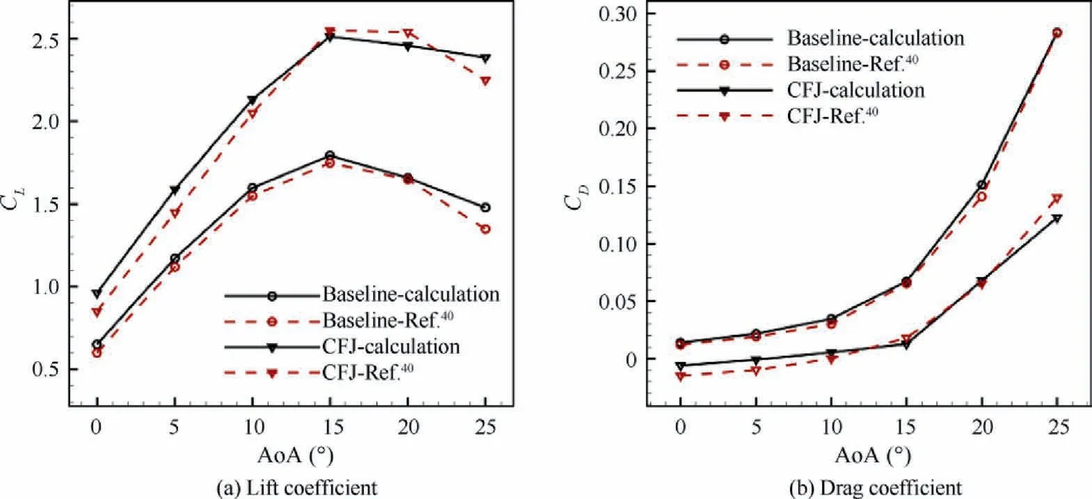
Fig. 5 Lift and drag coefficients of NACA6415 baseline and CFJ airfoil.
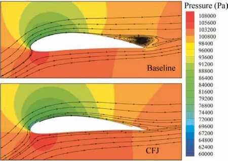
Fig.6 Comparison of pressure contours and streamlines around NACA6415 baseline and CFJ airfoil (AoA = 15°).
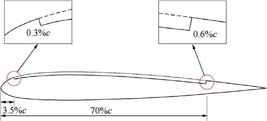
Fig. 7 SC1095 CFJ-stepped slot airfoil.
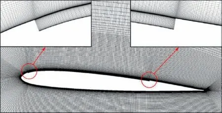
Fig.8 Computational mesh for SC1095 CFJ-stepped slot airfoil.

Fig. 9 Hysteresis loops of lift coefficient with different meshes.
Fig.13 shows the hysteresis loops of the lift coefficient,drag coefficient, moment coefficient, and lift-to-drag ratio of the SC1095 baseline airfoil and CFJ airfoil at C= 0.002. The area enclosed by the hysteresis loop of the lift coefficient,drag coefficient,and moment coefficient of the CFJ-sloping slot airfoil is greatly reduced,which means that the hysteresis effect is significantly weakened. This shows that the CFJ-sloping slot significantly suppresses the shock-induced dynamic stall.Meanwhile, the lift coefficient of the CFJ-sloping slot airfoil increases during the pitching process, and the peak value is 15.45%higher than that of the baseline airfoil.The drag coefficient decreases overall, and the peak value is 23.08% lower than that of the baseline airfoil.The lift-to-drag ratio increases significantly during the whole process, and its peak value increases by 14.89%. The negative peak value of the moment coefficient is also reduced by 30.59% compared with that of the baseline airfoil.This shows that the CFJ-sloping slot significantly improves the aerodynamic performance of airfoil.
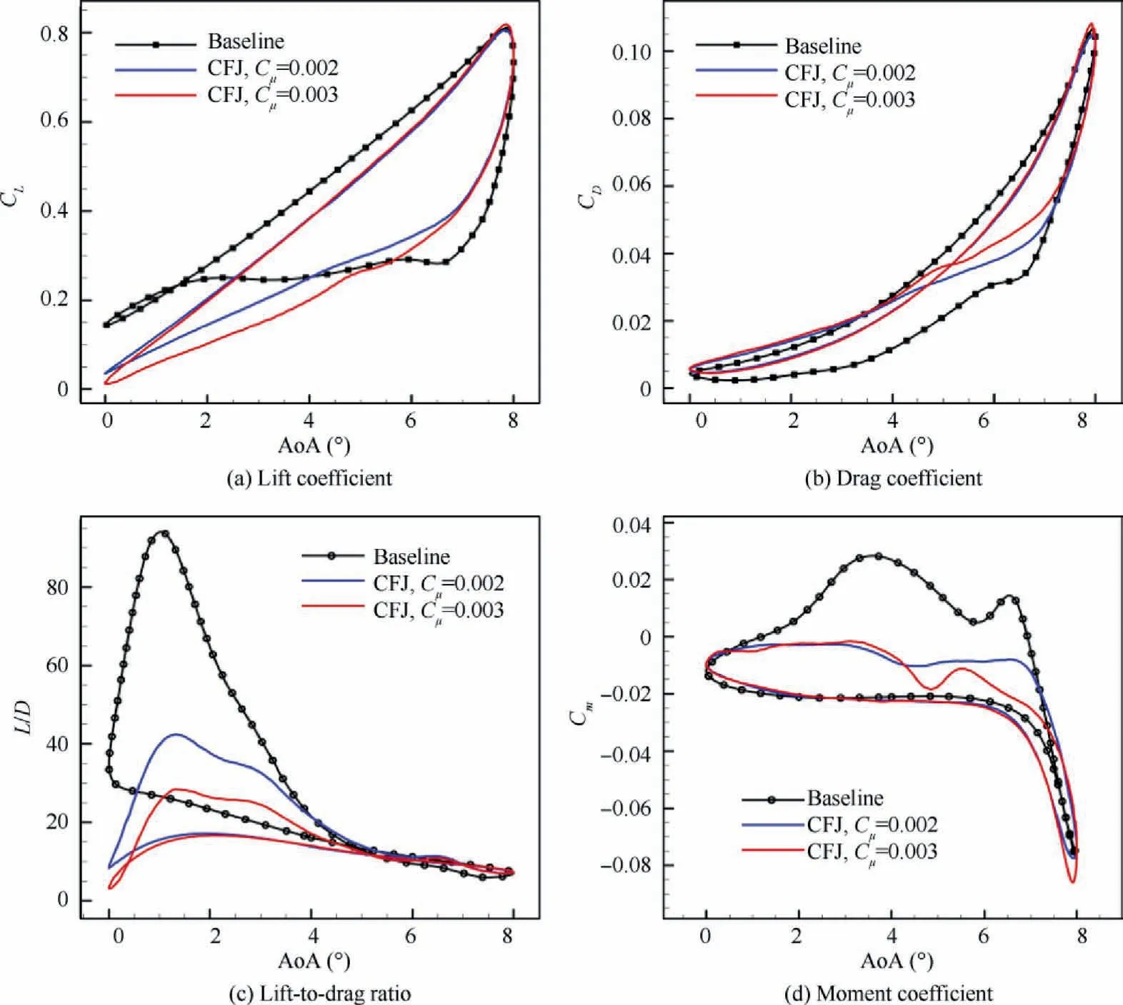
Fig. 10 Distribution of aerodynamic parameters of SC1095 baseline and CFJ-stepped slot airfoil.
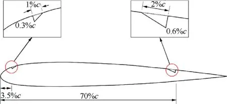
Fig. 11 SC1095 CFJ-sloping slot airfoil.
Fig. 14 shows the pressure coefficient distributions of the baseline airfoil and the CFJ airfoil at different AoAs. x/c is a dimensionless position along the chord,‘‘↓”indicates the airfoil is in the downward phase. The pressure coefficient of the lower surface of the airfoil remains unchanged after adopting CFJ control. However, the high-speed airflow injected by the air injection slot significantly reduces the pressure near the injection slot on the upper surface of the CFJ-sloping slot airfoil,and the area enclosed by the upper and lower surface pressure coefficient increases; therefore, airfoil lift increases. But the reduction of the pressure near the injection slot on the upper surface of the CFJ-stepped slot airfoil is almost zero at AoA=8°and that of the CFJ-stepped slot airfoil is significantly less than the CFJ-sloping slot airfoil at AoA = 6°↓.
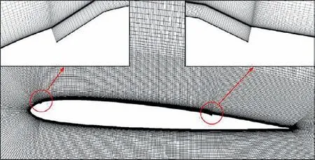
Fig. 12 Computational mesh for SC1095 CFJ-sloping slot airfoil.
Fig. 15 shows the Mach number contours and streamlines of the CFJ slot for two typical states of large flow separation.It can be found that the CFJ-sloping slot considerably suppresses flow separation on the upper surface of the airfoil.The jet is mixed with the mainstream to increase the flow velocity on the upper surface of the airfoil. However, it enhances the shock wave at the leading-edge of the airfoil, or generates a shock wave. The energy injected into the mainstream by the jet enhances the ability of the mainstream to resist adverse pressure gradient and inhibits flow separation.The benefits exceed the adverse effects caused by the shock waves.However,it is obvious that the CFJ-stepped slot almost cannot effectively suppress the flow separation. Hence, the effect of dynamic stall suppression based on the CFJ-stepped slot is weak.
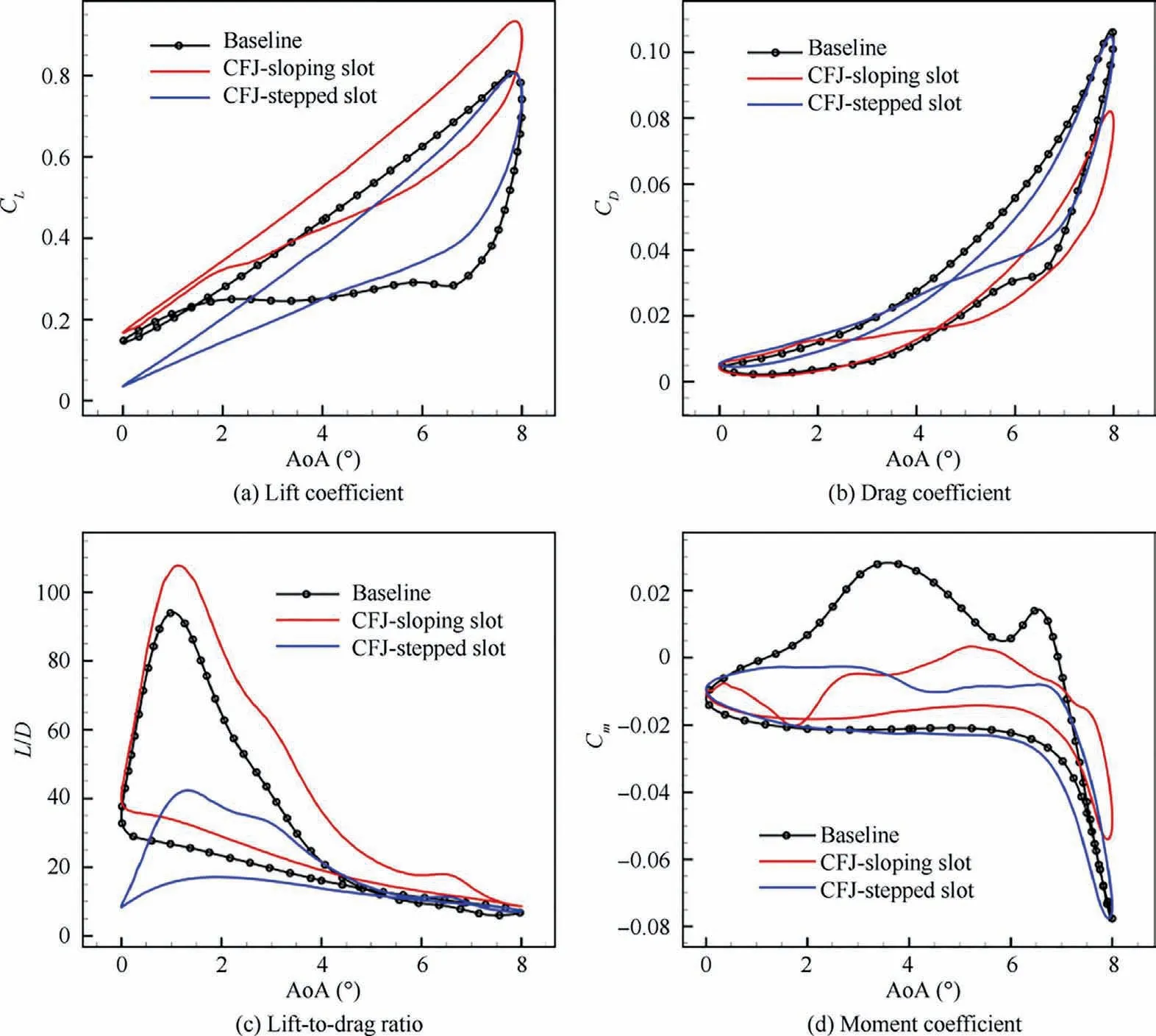
Fig. 13 Distribution of aerodynamic parameters of SC1095 baseline and CFJ airfoil.
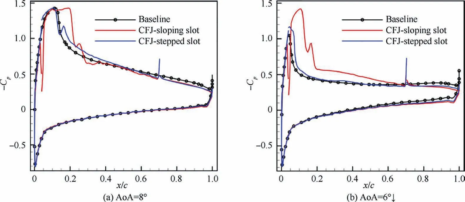
Fig. 14 Pressure coefficient distributions of SC1095 baseline and CFJ airfoil.
4.2. Dynamic stall suppression at high AoAs based on CFJ
Not only can a shock-induced dynamic stall of the helicopter blade occur at the advancing side, but a dynamic stall of the retreating side can also occur at high AoAs. The suppression of dynamic stall based on an improved CFJ airfoil at low speed and high AoAs is investigated in this section. The computational conditions are as follows: The Mach number is 0.15,the Reynolds number is 2.1×10,and the pitching motion follows Eq. (3), with the mean AoA α= 10°, the oscillation amplitude α= 10°, the reduced frequency k = 0.1, and the jet coefficient C= 0.08. Fig. 16 shows the lift coefficient and moment coefficient of the CFJ-stepped slot and CFJsloping slot airfoil compared with the baseline airfoil. The areas enclosed by the hysteresis loops of the lift coefficient and moment coefficient are both reduced, and the hysteresis effect is weakened. The lift coefficients of the two CFJ airfoils increase, the moment coefficients are greatly reduced, and the lift coefficient and moment coefficient curves of the two kinds of CFJ control airfoils coincide. This shows that the effect of dynamic stall suppression by the CFJ-sloping slot is almost equivalent to that of the traditional CFJ-stepped slot at low speed and high AoAs.
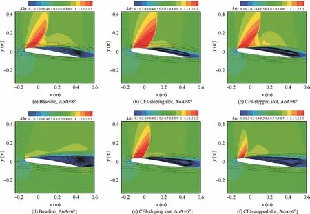
Fig. 15 Mach number contours and streamlines of SC1095 baseline and CFJ airfoil (Ma∞=0.7).
Fig.17 shows the comparisons of the flow field characteristics between the two kinds of CFJ airfoils and the baseline airfoil at different AoAs during airfoil oscillation. It can be seen that the two kinds of CFJ suppress flow separation considerably on the upper surface of the airfoil, and their suppression effects are almost the same.
Based on the above analysis, the CFJ-sloping slot does not only suppress the shock-induced dynamic stall of the rotor airfoil,but also dynamic stall at low speed and high AoAs.Therefore, this improved CFJ is a potential flow control technique that simultaneously suppresses both the dynamic stall on the advancing side and the dynamic stall on the retreating side.
4.3. Mechanism of dynamic stall suppression based on CFJ
The mechanism of the improved CFJ in suppressing the dynamic stall of the rotor airfoil is studied in this section.Fig. 18 and Fig. 19 show the streamlines around the CFJsloping slot and CFJ-stepped slot airfoil at high Mach number and low Mach number,respectively.The CFJ-sloping slot converges along the slope to the main flow after being ejected from the injection slot at high speed; and because the high-speed flow has a certain degree of compressibility,the flow tube near the wall shrinks.The CFJ-stepped slot flows along the tangential direction of the airfoil surface after being ejected from the injection slot, and the flow tube does not shrink, which makes the flow velocity of the near-wall airflow of the CFJ-sloping slot higher than that of the CFJ-stepped slot.This is beneficial for enhancing the resistance to adverse pressure gradient. In addition,although the CFJ-sloping slot will also converge with the main flow upwards along the slope at low speed, the lowspeed flow is almost incompressible, and therefore, the flow tube shrinks only slightly. Therefore, the speed of the CFJsloping slot airfoil surface is close to that of the CFJ-stepped slot.
Fig. 20 and Fig. 21 show the surface velocity profile of the CFJ-sloping slot and CFJ-stepped slot airfoil behind the injection slot at high Mach number and low Mach number,respectively. For the high-speed conditions, the surface velocity of the CFJ-sloping slot airfoil is greater than that of the CFJstepped slot airfoil at x = -0.124 m, where the jet is just ejected from the injection slot,and the velocity profile is fuller.The surface velocities of the two types of CFJ airfoils are higher than that of the baseline airfoil at x = -0.1 m, where the jet has mixed with the main flow. With the same jet momentum coefficient, the surface velocity of the CFJsloping slot airfoil is greater than that of the CFJ-stepped slot airfoil, and the velocity profile is fuller. With the momentum coefficient increases, the surface velocity of the CFJ-sloping slot airfoil increases, while the surface velocity of the CFJstepped slot airfoil remains almost unchanged.This means that the speed of the CFJ-stepped slot is too low to resist the adverse pressure gradient of the airfoil surface flow.Therefore,the CFJ-sloping slot suppresses dynamic stall better than the CFJ-stepped slot at high speed.
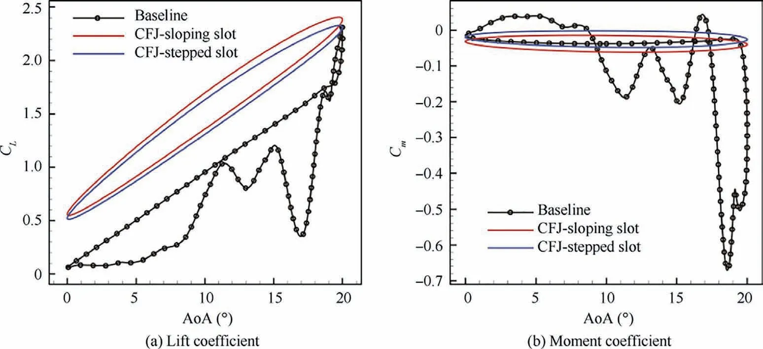
Fig. 16 Aerodynamic parameters of SC1095 baseline airfoil and CFJ airfoil (Ma∞=0.15).
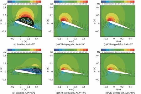
Fig. 17 Mach number contours and streamlines of SC1095 baseline and CFJ airfoil (Ma∞=0.15).
Under the low-speed conditions, the surface velocity of the CFJ-sloping slot airfoil is higher than that of the CFJ-stepped slot airfoil, in which the velocity profile is fuller, and both are higher than that of the baseline airfoil.The surface velocity of both kinds of CFJ airfoils increases with increasing jet momentum coefficient, with that of the CFJ-sloping slot becoming slightly greater, meaning they both successfully suppress flow separation. This explains how both the CFJ-sloping slot and the CFJ-stepped slot successfully suppress dynamic stall at low speed, and how the control effects of the two are equivalent.
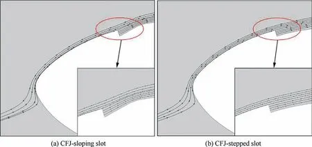
Fig. 18 Comparison of streamlines around CFJ airfoils (Ma∞=0.7, AoA = 6°↓, Cμ = 0.003).
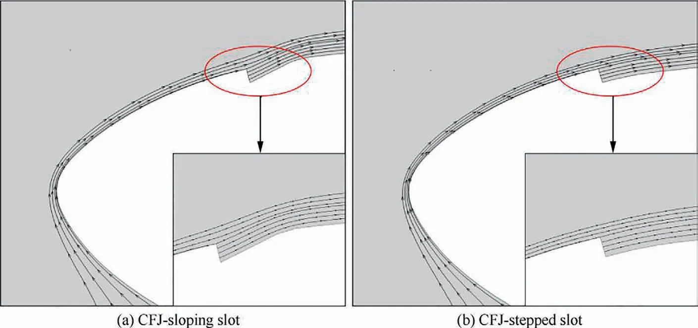
Fig. 19 Comparison of streamlines around CFJ airfoils (Ma∞=0.15, AoA = 10°↓, Cμ = 0.08).

Fig. 20 Surface velocity profile of CFJ-sloping slot and CFJ-stepped slot airfoil behind injection slot (Ma∞=0.7, AoA = 6°↓).
5. Parameters analysis of shock-induced dynamic stall suppression based on CFJ-sloping slot
The effect of improved CFJ parameters on the shockinduced dynamic stall of the SC1095 rotor airfoil is investigated. The parameters include the jet momentum coefficient,the position and size of the injection slot, and the position and size of the suction slot. A sketch of the SC1095 CFJ airfoil geometric parameters is shown in Fig. 22. x, h,x, and hare the position of the injection slot, size of the injection slot, position of the suction slot, and the size of the suction slot, respectively.
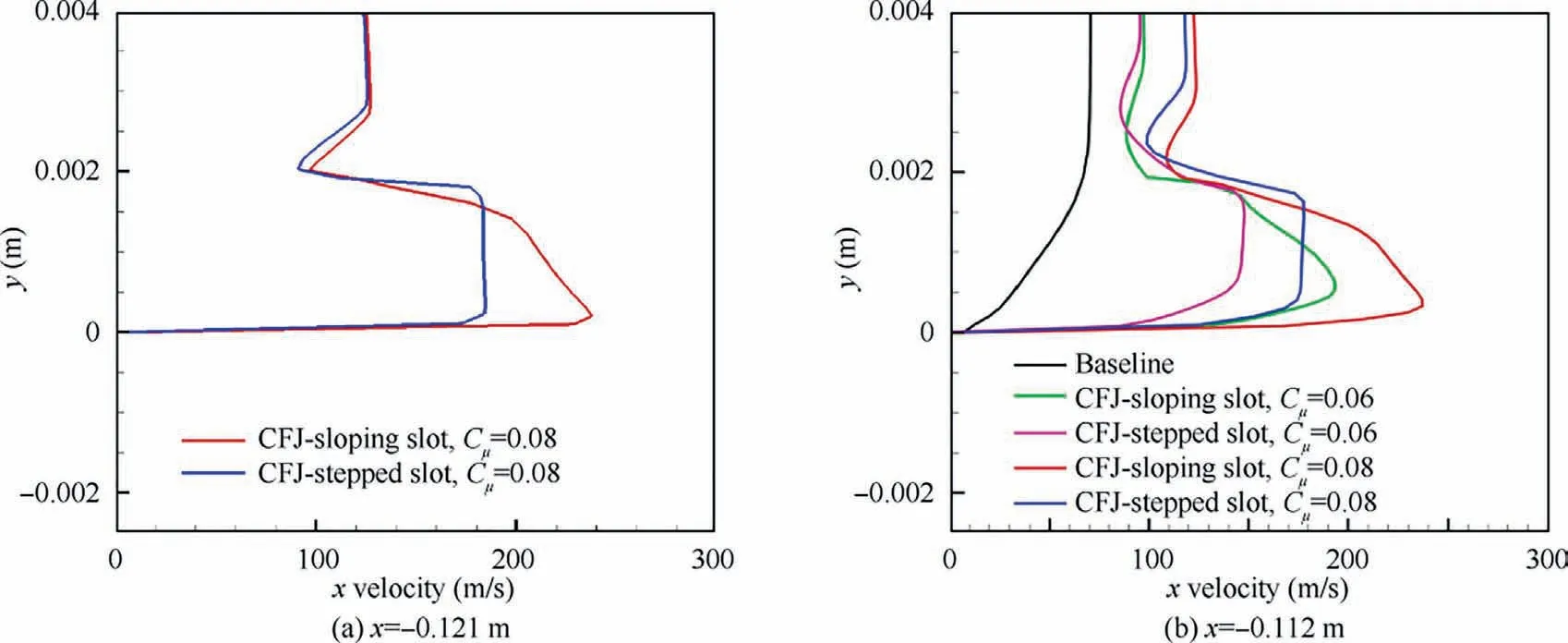
Fig. 21 Surface velocity profile of CFJ-sloping slot and CFJ-stepped slot airfoil behind injection slot (Ma∞=0.15, AoA = 10°↓).
5.1. Jet momentum coefficient
The geometric parameters of the CFJ-sloping slot are as same as those in Section 4.1. We examined the effects of shockinduced dynamic stall suppression with different jet momentum coefficients (C= 0.002,0.003,0.0035).
Fig. 23 shows the Mach number contours and streamlines of the CFJ-sloping slot airfoil, with different jet momentum coefficients. Two typical AoAs, a maximum AoA of 8°(AoA = 8°) and AoA = 6° at the downstroke (AoA = 6°↓), are selected for analysis. The calculations show that the CFJ-sloping slot, with different jet flow coefficients, significantly suppresses shock-induced flow separation. With the increase of the jet momentum coefficient, the shock wave at the leading-edge of the airfoil moves toward the trailingedge, reducing the range and enhancing the suppression of flow separation.
Fig. 24 shows the pressure coefficient distributions of the SC1095 baseline airfoil and CFJ-sloping slot airfoil with different momentum coefficients. The graph reveals that with the increase of the jet momentum coefficient, the shock wave moves back toward the trailing-edge and the area enclosed by the pressure coefficient loop is bigger which enhances lift.
To further study the effect of different jet momentum coefficients on shock-induced dynamic stall suppression, the hysteresis loops of lift, drag, and moment coefficient in the process of pitch are plotted in Fig. 25. Clearly, the larger the jet momentum coefficient, the larger the increase in the peak value of the lift coefficient, which increases by about 18%,and the smaller area closed by the hysteresis loop, meaning the hysteresis weakens.However,the drag coefficient decreases less with increasing the jet momentum coefficient,and its peak value also decreases less. In addition, the peak value of the moment coefficient decreases less, which decreases by about 26%, and the degree of fluctuation becomes more severe, as the jet momentum coefficient increases,which is not conducive to system stability.
5.2. Injection slot parameters
The effect of the injection slot position of the CFJ-sloping slot airfoil on dynamic stall is investigated.Keeping the size of the injection/suction slot and the position of the suction slot constant,the jet momentum coefficient C=0.003.The injection slot is installed near the leading-edge, 2.5%c to 4.0%c,where the shock wave is generated at a high AoA. The hysteresis loops of the lift coefficient, drag coefficient, and moment coefficient with AoA are shown in Fig. 26. The more forward the position of the injection slot, the greater the peak value of the lift coefficient, the smaller the area of the hysteresis loop.The drag coefficient overall decreases greater,but the peak value decreases less. Similarly, the moment coefficient overall decreases greater,but the decrease of the moment peak value is reduced.
The effect of the injection slot size of the CFJ-sloping slot airfoil on dynamic stall is investigated for a jet momentum coefficient C= 0.003. The injection slot size varies from 0.20%c to 0.35%c, and the other parameters remain unchanged. Fig. 27 shows the distributions of the lift coefficient, drag coefficient, and moment coefficient with AoA. It is obviously found that the injection slot size has a significant effect overall on the dynamic stall suppression. The lift coefficient increases and the drag coefficient decreases more sharply when the injection slot is smaller, and the hysteresis effect weakens more markedly. As the injection slot size decreases,the reduction degree of the moment coefficient peak value decreases slightly, while the degree of oscillation of the moment coefficient remains almost constant.
5.3. Suction slot parameters
The effect of the suction slot position of the CFJ-sloping slot airfoil on dynamic stall is studied by varying the suction position from 60%c to 80%c.Keeping the size of the injection/suction slot and the position of the injection slot constant, the jet momentum coefficient C=0.003.Fig.28 shows that the relationship between the suction slot position and the dynamic stall suppression is not positively correlated. The suppression effect is best when the suction slot is at 75%c.At this position,the lift coefficient increases most,the drag coefficient decreases most, and the moment coefficient oscillates slightly. Dynamic stall suppression will be weakened when the suction slot is installed too far forward or too far behind.

Fig. 22 SC1095 CFJ airfoil geometric parameters.
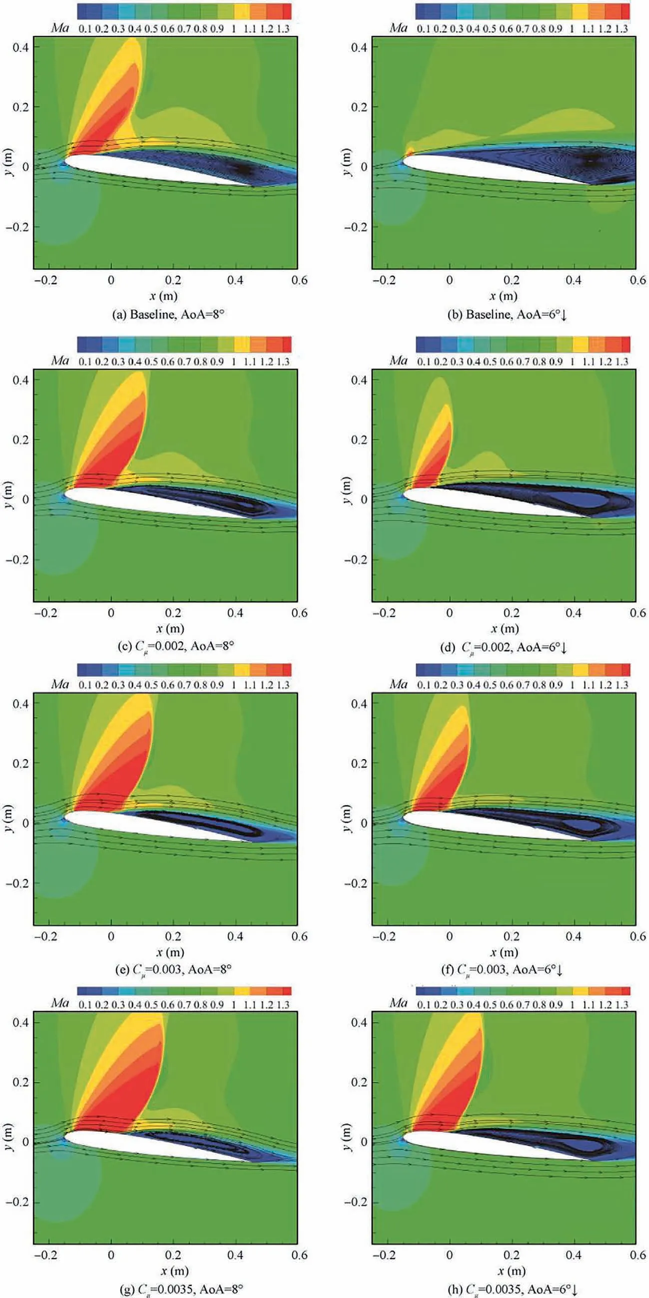
Fig. 23 Mach number contours and streamlines with different jet momentum coefficients.
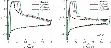
Fig.24 Pressure coefficient distributions of SC1095 baseline airfoil and CFJ-sloping slot airfoil with different jet momentum coefficients.

Fig. 25 Aerodynamic parameter distributions of CFJ-sloping slot airfoil with different jet momentum coefficients.

Fig. 26 Aerodynamic parameter distributions of CFJ-sloping slot airfoil with different injection slot positions.
The effect of the suction slot size of the CFJ-sloping slot airfoil on dynamic stall is studied by varying the suction size from 0.55%c to 0.70%c. Keeping the position of the injection/suction slot and the size of the injection slot constant,the jet momentum coefficient C= 0.003. Fig. 29 shows the hysteresis loops of the lift coefficient, drag coefficient, and moment coefficient of the CFJ-sloping slot airfoil with different suction slot sizes. Suction slot size is positively correlated with dynamic stall suppression. As the suction slot size increases,the hysteresis effect clearly weakens.The peak value of the lift coefficient increases greater, and the drag coefficient decreases more. The decrease in the moment coefficient peak value and the degree of oscillation of the moment coefficient remain almost constant.Therefore,the suction slot size should be increased as much as possible to meet other design conditions.

Fig. 27 Aerodynamic parameter distributions of CFJ-sloping slot airfoil with different injection slot sizes.

Fig. 28 Aerodynamic parameter distributions of CFJ-sloping slot airfoil with different suction slot positions.

Fig. 29 Aerodynamic parameter distributions of CFJ-sloping slot airfoil with different suction slot sizes.
6. Conclusions
The dynamic stall suppression of a rotor airfoil SC1095 based on co-flow jet is investigated in this work. An improved coflow jet, which better suppresses the shock-induced dynamic stall than a traditional co-flow jet,is proposed.The mechanism and the effects of dynamic stall suppression are explored. The following conclusions can be drawn:
(1) The improved CFJ, i.e., the CFJ-sloping slot, suppress the shock-induced dynamic stall better than a traditional CFJ, and it successfully suppresses dynamic stall at low-speed and high angles of attack.
(2) For the suppression of shock-induced dynamic stall,the CFJ-sloping slot airfoil is favorable to converge the jet with the main flow. Because the high-speed flow has certain compressibility which causes the flow tube near the airfoil surface to shrink, it is beneficial for enhancing resistance to adverse pressure gradient and suppressing shock-induced dynamic stall. For suppression of dynamic stall at low-speed and high angles of attack, due to the jet is almost not compressible and the flow tube does not shrink, the airfoil surface velocity of the CFJ-sloping slot is closed to the CFJstepped slot. Therefore, the effects of dynamic stall suppression using both CFJ techniques are almost equivalent.
(3) With increasing jet momentum coefficient,the lift coefficient increases greater whose peak value increases by about 18%,and the area enclosed by the hysteresis loop is smaller, meaning the hysteresis effect weakens. However, with increasing jet momentum coefficient the moment coefficient decreases less whose peak value decreases by about 26%, and the degree of fluctuation of the rotor airfoil becomes more severe, which is not conducive to system stability.
(4) The CFJ injection slot is located more forward to leading-edge, near the 2.0%c, the effect of shockinduced dynamic stall suppression is better.The lift coefficient increases and the drag coefficient decreases more sharply when the injection slot is smaller. Besides, the dynamic stall suppression is not positively correlated with the suction slot position,and the suppression effect maximizes when the suction slot is at 75%c. The size of the suction slot should be designed as bigger as possible.
Based on the analysis of the numerical results of the twodimensional rotor airfoil, some suggestions are obtained for the design of helicopter rotors. The CFJ-sloping slot rotor is a promising configuration for the high-speed helicopter to suppress the dynamic stall. The jet momentum coefficient, position and size of the slot are significant for the dynamic stall suppression,and these parameters should be adjusted carefully to make a better effect. For different types of helicopters, the different positions and sizes of the injection/suction slot should be designed.
The authors declare that they have no known competing financial interests or personal relationships that could have appeared to influence the work reported in this paper.
The work was supported by the National Natural Science Foundation of China (No. 12072305), Equipment Field Preresearch Fund, China (No. 61402060205), the Open Fund from Rotor Aerodynamics Key Laboratory of China Aerodynamics Research and Development Center, China (No.RAL20190303), the Aeronautics Power Foundation, China(No. 6141B09050347).
