Robust spline-line energy management guidance algorithm with multiple constraints and uncertainties for solid rocket ascending
Songyan WANG,Fei LIU,Tao CHAO,Ming YANG
Control and Simulation Center,Harbin Institute of Technology,Harbin 150001,China
KEYWORDS Ascent guidance;Energy management;Multiple constraints;Solid rockets;Uncertainty;Velocity capability curve
Abstract For the solid rocket with depletion shutdown system,effective energy management is significant to meet terminal constraints by exhausting excess energy.Several traditional energy management algorithms cannot satisfy the altitude constraint and path constraints are not sufficiently considered.The velocity adjustment capability of these algorithms is limited and the uncertainties are not considered.Based on the on-line programming of velocity capability curve,Spline-Line Energy Management (SLEM) guidance algorithm is proposed.It introduces lateral maneuvers to further consume the available velocity on the basis of longitudinal energy management.After expressing the constraints as several algebraic equations,the closed-loop guidance problem is converted to solving a system of nonlinear equations about the curve parameters in real time.The advantage is that the altitude constraint can be satisfied theoretically.The overload and control variable change rate and amplitude constraints are also considered during the flight by constructing the feasible boundary of velocity capability curve.To improve the robustness,it is further extended by estimating the actual uncertainties.The effectiveness and advantages of SLEM are demonstrated by simulations and comparisons with other energy management algorithms.Simulation results show that the proposed approach can satisfy multiple constraints with high precision under the condition of uncertainties.
1.Introduction
Compared with liquid rockets,Solid Launch Vehicles (SLVs)have the characteristics of simple structure,good safety,high reliability,easy maintenance,and short preparation time.They are widely used in aviation and aerospace fields.With respect to launch missions,SLVs need to reach a certain altitude with the specified attitude and velocity.As for SLVs,rapid ascent trajectory optimization methods are widely studied considering terminal and path constraints based on the optimization theory.Using the indirect methods,the ascent trajectory optimization problem is transformed into Hamilton Two-Point Boundary Value Problems (TPBVPs) based on the optimal control theory.It is well known that the optimality conditions of optimal control problem with many constraints will be very complex,which causes high sensibility to the initial guess.So,the direct methods are more widely used in engineering,such as Gaussian pseudo-spectral method in the flight strategy optimization.
Some adaptive guidance methods are also studied in recent years.However,in some extreme cases,the reliability of guidance algorithm cannot be guaranteed as the dynamical model changes significantly.Therefore,ascent guidance algorithms or online trajectory optimization methods with stronger robustness need to be developed.Most researchers focus on formulating the nonconvex optimal problem within the convex framework,which is called convexification.The lossless convexification technique has been successfully applied in ascent flight of launch vehiclesand guided rockets.However,most path and terminal constraints as well as nonlinear dynamic cannot be convexified by lossless convexification.Successive convexification is proposed to convexify the complex nonconvex and nonlinear constraints.The convex optimization has been successfully applied in spacecrafts,high-speed atmospheric vehicles,etc..An uncertainty-based multidisciplinary design optimization method,combined with fuzzy theory and multi-discipline feasible method,is developed for the conceptual design of a launch vehicle powered by hybrid rocket motor.
In recent years,the concept of computational guidance is widely studied by scholars.Based on the Model Predictive Control (MPC) and predictor-corrector idea,several ascent guidance algorithms are proposed.An adaptive optimal trajectory tracking controller is presented for the SLVs with uncertain nonlinear non-affine dynamics in the framework of adaptive dynamic programming.An integrated approach that considers the performance limitations of tracking control systems is proposed.However,for practical ascent application of solid rockets,the high time consumption of these approaches makes them difficult to meet the real-time requirements of the ascent guidance task.Therefore,the real-time performance of these new energy management ideas is still required to be further improved.
The engine shutdown time of solid rockets is not controllable.In order to obtain the energy for a specific flight mission,the Depleted Shutdown(DS)technology must be adopted.The desired speed is achieved by changing the flight attitude before the shutdown.In recent years,with the rise of boost-glide vehicle,high orbit interception and other topics,solid rockets energy management guidance,as a key technology,has once again become a hot spot and received wide attention.Considering that the first and second stages of SLVs fly within the atmosphere,it is not conducive to large maneuvers.Therefore,only the last stage adopts the energy management strategy in the exo-atmosphere.
Over the past few decades,numerous efforts have been devoted to the energy management algorithm development of launch vehicles.Several DSEM algorithms are based on the zero-range orientation.These algorithms are not sensitive to the deviation of the shutdown time.However,multiple constraints cannot be satisfied.Some other algorithms have the ability of velocity control,which guides the rocket to achieve the specified velocity vector when the engine shuts down.Patha and Mageheestudied the Attitude Energy Management (AEM) approach based on pitch alternating attitude control,which divides the energy management flight into six segments.The attitude angle change curve of each segment needs to be calculated in advance.Yao et al.proposed a single adjustment approach of attitude angle for solid rocket depleted shutdown energy management.Wang et al.proposed an energy management method based on AEM deviation correction to reduce the tracking error caused by neglecting the dynamic characteristics of angular velocity.However,the above methods are open-loop guidance laws.If disturbance happens during the actual flight,the guidance accuracy would be low.For closed-loop energy management,Zarchanhas studied a General Energy Management(GEM) method,which uses arc trajectory to manage excess energy.This method is simple and accurate,but it cannot control the energy dissipation intensity.Thus the attack angle of the starting and ending point of energy management is large.The Spline Energy Management (SEM) was proposed,which needs to solve the integral equation in real time.An energy management method based on dynamic inversion was proposed.Both of SEM and IEM have the ability of terminal velocity and angle control,but cannot achieve the altitude constraint.An offline trajectory optimization method was proposed to design a nominal trajectory that satisfies multiple constraints.Although the accuracy of the algorithm is high,it does not have the ability of online adaptation.And the single-cycle yaw energy management will make the lateral displacement not converge.In addition,the method of multiconstraint closed-loop guidance in boost phase was studied by the minimum principle.The energy management of the vertical,horizontal and spiral motion of missiles with solid rocket motors were studied.A lateral energy management method was proposed.Due to severe coupling between the longitudinal and lateral planes,the lateral guidance command will affect the longitudinal trajectory and further affect the terminal altitude.Several new developments were made to refine and expand the capability of an optimal ascent-guidance algorithm,and then seamless integration of the guidance algorithm was proposed.Xu and Zhangproposed a multi-constrained guidance method for the ascent phase of solid propellant launch vehicles,where a pointing algorithm formed the baseline guidance law and an energy management technique was developed for dissipating the extra energy when the engine was shut off by fuel exhaustion.Zhang and Xuproposed an improved analytic algorithm for rapid and automated ascent guidance of responsive small solid launch vehicles shutting off by fuel exhaustion,where a velocity increment control method was derived from the minimum steering angle constraints to dissipate the extra energy and an improved pointing algorithm was constructed to restrain the coupling vectors.
This paper proposes an improved energy management guidance algorithm,Spline-Line Energy Management(SLEM),which not only satisfies all the constraints mentioned above,but also includes the terminal altitude constraint which is difficult to solve with traditional methods.Traditional energy management is only guided in the longitudinal plane.Therefore,it leads to the limitation of the velocity exhaustion capability.The SLEM algorithm extends the two-dimensional motion to the three-dimensional space.It introduces the lateral plane velocity exhaustion,which enhances the capability of energy management and enlarges the reachable area.The SLEM is a closed-loop ascent guidance algorithm which can achieve online guidance by programming the velocity capability curve in real time.One of the straightforward ideas for finding a velocity capability curve is to construct a space curve.Its length and endpoints meet the corresponding constraints.However,it is difficult to express the altitude increment through a three-dimensional space velocity capability curve.In addition,due to the coupling between longitudinal and lateral planes,the process of solving equations by numerical methods becomes complicated.Therefore,this paper proposes an approach which decomposes the space curve into two plane curves,longitudinal plane and lateral plane.It transforms the problem of solving a high-order spline curve into solving two low-order spline curves.The advantage of the approach is that it avoids the difficulty of space curve integration and provides a preliminary decoupling at the same time.It simplifies the calculation of partial derivatives in numerical algorithms as well.By curve integration and derivative decomposition,the altitude increment and lateral displacement can be expressed as an algebraic function on the parameters of the two spline curves.In this way,while meeting the velocity and angle constraints,the altitude constraint is satisfied by solving the spline parameters as well.Furthermore,in order to meet the mission,the rocket should return to the longitudinal plane and velocity vector needs to be located in the longitudinal plane at the terminal moment.Therefore,the lateral displacement and lateral velocity need to converge to zero.Based on the current states and the desired terminal constraints of velocity and altitude,the spline velocity capability curve is updated by solving a system of nonlinear equations during each guidance period.In addition,based on the actual flight situation,the constraint of the control change rate is considered to satisfy the limit of the actuator.Overload constraints are also considered to ensure stability of the attitude control system and prevent structural damage to the rocket.In actual flight,perturbation often exists in specific impulse and mass flow rate.Therefore,aimed at these uncertainties,robust energy management is further studied.The basic idea is to estimate the uncertainties by Extended State Observer (ESO) and then compensate for remaining velocity capabilities.Finally,the thrust vector drives the velocity vector along the resulting curve,and the attitude command is obtained according to the direction of thrust vector.The efficiency and applicability of SLEM are demonstrated through various combinations of different desired terminal altitude and velocity.And the Monte Carlo simulations of thrust perturbation show the robustness of the algorithm.
The major contributions of this study can be summarized as follows:
(1) An improved three-dimensional energy management algorithm is proposed in this paper.In addition to terminal velocity and LTIA,it can satisfy the terminal altitude constraint in particular which is difficult to be satisfied using traditional methods,such as SEM.Meanwhile,it extends the energy management from the traditional longitudinal plane to the threedimensional space which expands the adjustable range of terminal velocity.
(2) This paper considers path constraints,which are control variable change rate constraint,amplitude constraint and overload constraint.It transforms the constraints into functions of local horizontal velocity and constructs the feasible boundary of velocity capability curve.The velocity capability curve should be within the feasible boundary at any time.
(3) This paper extends the energy management under nominal conditions to a robust energy management with uncertainties.By using the ESO,the actual thrust can be estimated and the remaining velocity capabilities can be compensated.It enhances the robustness of the algorithm.
(4) Through deducing the velocity capabilities attributed to the thrust in the longitudinal and lateral plane respectively,an approach is proposed,which converts the problem of solving a space velocity capability curve into that of solving two plane velocity capability curves.
(5) Through expressing the lateral displacement analytically,the algorithm proposed in this paper achieves the lateral displacement,and lateral velocity converges to zero and returns to the plane of launch at the terminal time.
The remainder of this paper is organized as follows.In Section 2,some preliminaries are presented.The dynamic model and the main principle of the energy management are illustrated.In Section 3,the proposed SLEM algorithm is described in details with the path constraints and uncertainties considered.In Section 4,some numerical simulations and comparison results are presented,and the effectiveness of the SLEM is tested and verified.
2.Preliminaries
2.1.Ascent dynamic model
The ascent dynamic model of the solid rocket is established in the launch coordinates,as shown in Fig.1.The ascent dynamic model in three-dimensional space can be decomposed into longitudinal plane and lateral plane.v is the velocity of the vehicle.vand vare the velocity projection in horizontal and lateral plane respectively.Pis engine thrust along the vehicle body axis.Pand Pare the thrust projection in the horizontal and lateral plane respectively.Θ is Local Trajectory Inclination Angle (LTIA).θ is trajectory inclination angle.Φ is the angle between vehicle body axis and local horizontal plane,named Local Pitch Angle (LPA).α is angle of attack.Σ is Local Trajectory Azimuth Angle (LTAA).σ is trajectory azimuth angle.Ψ is the angle between vehicle body axis and local vertical plane,named Local Yaw Angle (LYA).β is angle of sideslip.D,L and R are the drag,lift and side force respectively.G is the gravity.In particular,the normal body variable is the module of the corresponding boldface variable in this paper.
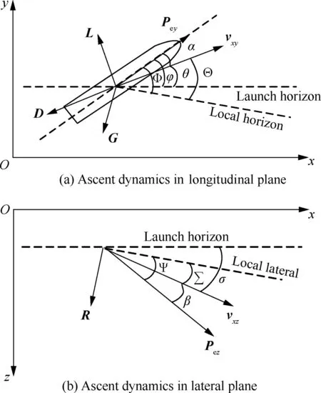
Fig.1 Ascent dynamics in launch coordinates.
To simplify the calculation,several assumptions are made about the model.First,the vehicle is treated as a particle and the rotation is ignored.Second,the effect of the swing nozzle is not considered.Third,the Earth is treated as a sphere.Fourth,Coriolis and centrifugal forces are ignored.Fifth,the change in gravity acceleration with altitude is ignored.Based on the above assumptions,the longitudinal-lateral planes ascent dynamics are presented as follows:

whereis altitude;is lateral displacement; Pandare the engine thrust and vehicle mass respectively;is gravity acceleration.
2.2.Basic principle of energy management
To explain the basic principle of the energy management guidance algorithm,the local horizontal-vertical velocity frame in the pitch plane is presented in Fig.2.Theandaxes represent the local horizontal velocity and the local vertical velocity respectively.Since the terminal LTIA is expected to be 0,the target velocity vector vis along the direction of x axial.Thus,it can be obtained that the velocity to be gained Δv is
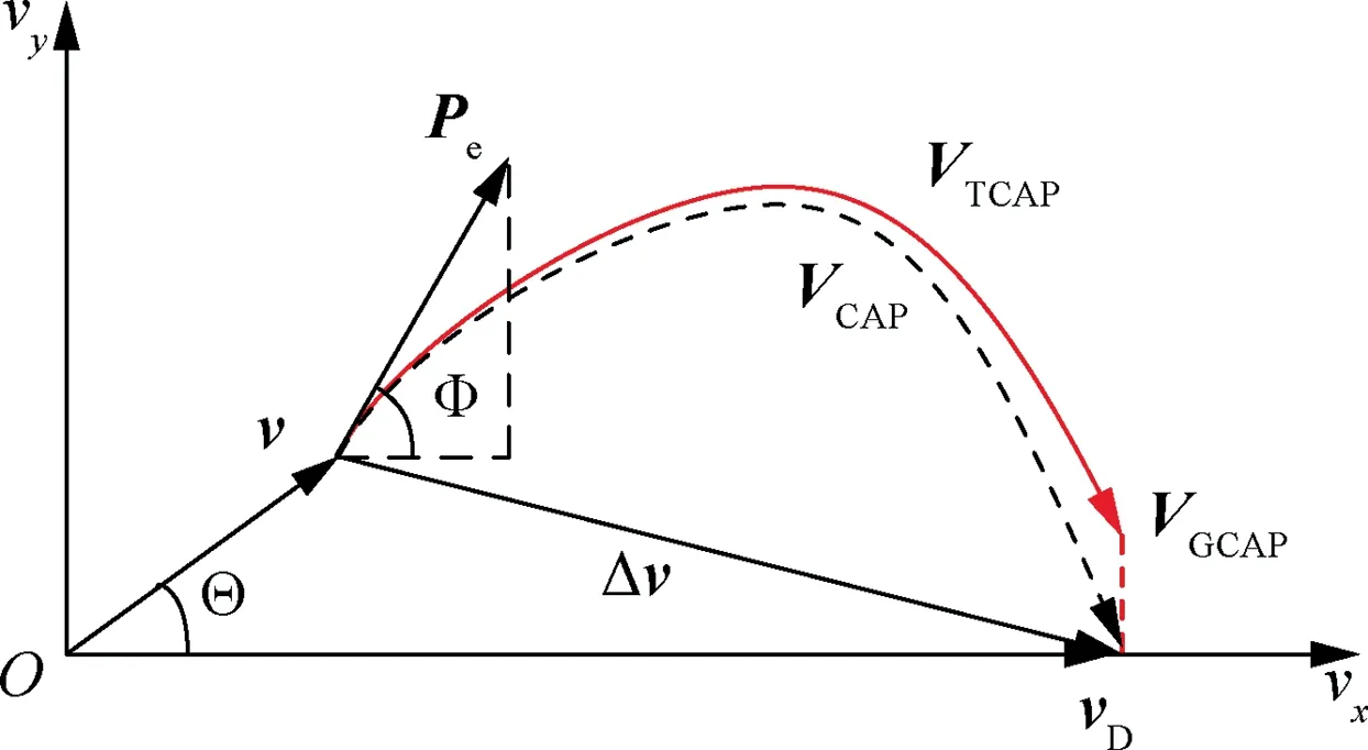
Fig.2 Basic principle of energy management.

For the fuel-exhaustion-shutoff solid rocket,EM is to exhaust the excess energy provided by the engine.Vis the velocity capability.The magnitude of Vis much larger than that of the velocity to be gained Δv.In this paper,as the last stage is almost out of the atmosphere,the aerodynamic forces can be negligible.Therefore,Vcan be divided into Vand Vwhich are the velocity capability attributed to the thrust and gravity respectively.


Considering the rotation of the local horizontal direction relative to the initial horizontal direction,the modulus of Vcan be expressed as


The basic principle of EM is shown in Fig.2.After Δv is obtained,the EM guidance method is to design a curve so that its length is equal to‖V‖and the projection in the direction of Δv is consistent with ‖Δv‖.The guidance process is achieved by controlling the direction of the engine thrust.Attitude control system keeps the direction of Ptangent to Vat all time and drives the actual velocity v along the designed EM velocity curve Vto the desired terminal vectorv.The details of the basic principle of EM are shown in Ref.
3.Spline-line energy management guidance algorithm
In this section,the design and solution of the SLEM method are proposed.Since it is difficult to obtain the space curve Vdirectly,Vcan be divided into two plane curves Vand V,as shown in Fig.3.Vand Vare the velocity capabilities attributed to the thrust in the longitudinal and lateral plane respectively.The advantage of the algorithm is that it avoids the difficulty of space curve integration and provides a preliminary decoupling at the same time.In longitudinal plane,the initial point of Vis the current velocity (v,v) and the end point is the terminal velocity(v,V).In lateral plane,the initial point of Vis the current velocity (v,v) and the end point is the terminal velocity (v,0).The two curves are both spline curves and exhaust the longitudinal and lateral velocity capability respectively.
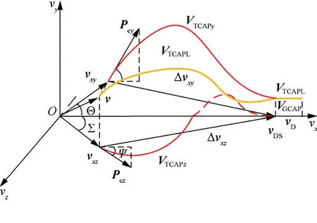
Fig.3 Three-dimensional energy management.
Fig.4 shows the main idea of the proposed SLEM algorithm which describes the progress of dimensionality reduction.
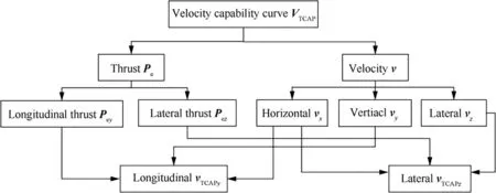
Fig.4 Main idea of SLEM algorithm.
3.1.Calculation of

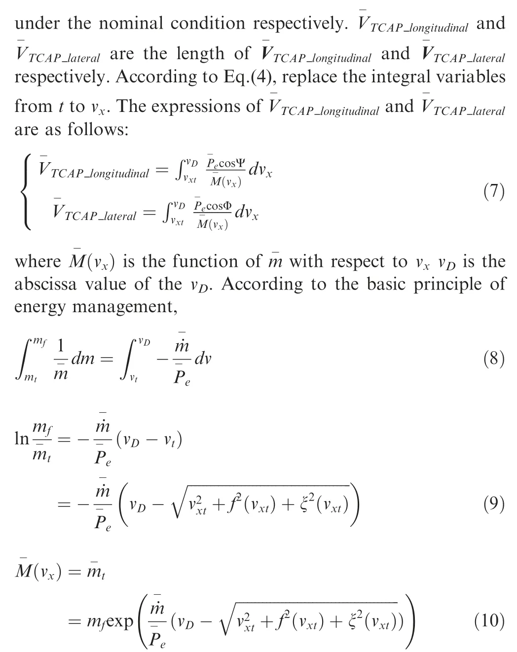
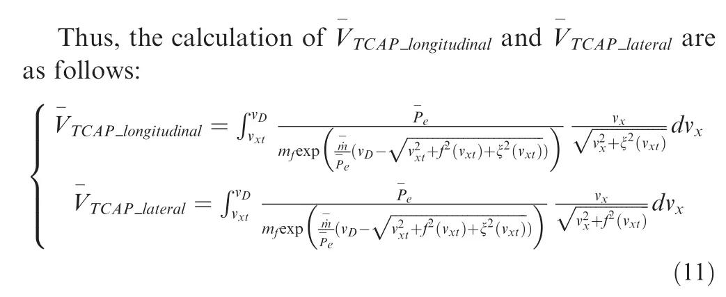
3.2.Design of spline curve VTCAPy
In the Spline-Line Energy Management (SLEM) method proposed in this paper,the Vcurve is shown in Fig.5.The initial point of Vis the current velocity (v,v) and the end point is the velocity (v,V).Vis designed as a spline curve.It exhausts the velocity capability Vand causes an altitude increment ΔH.vis the abscissa of the terminal velocity in the spline curve phase.
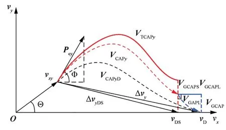
Fig.5 Longitudinal SLEM.

where Vand Vare the length of Vand Vrespectively;ΔHis the altitude increment caused by Vwhich is the level-flight phase discussed in the next section.
V
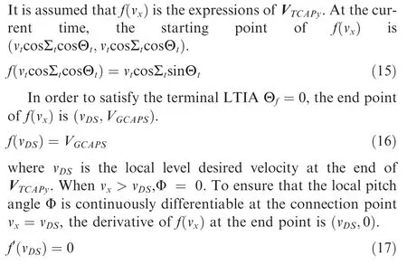
In order to guarantee that the velocity capability attributed to thrust in the longitudinal plane is completely exhausted when vis reached,

ΔH
When the velocity goes from A (v,(v)) to B (v,(v))along the curve V,the altitude increment Δhis

Since it is difficult to calculate ∂Δh/∂vdirectly,it can be expanded into the product of several derivatives which are easy to solve.
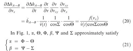
Substituting Eq.(21) into Eq.(1) yields
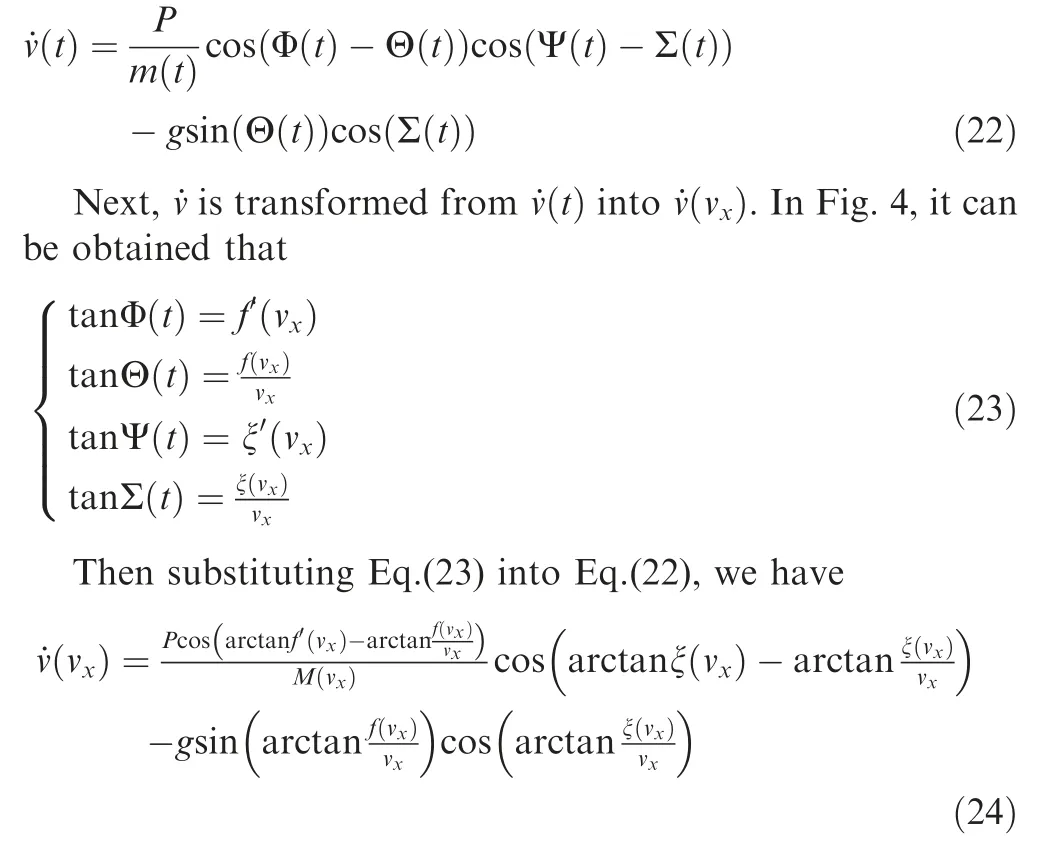
Therefore,when the velocity goes from A to B along V,the altitude increment Δhis

The altitude increment ΔHattributed to Vfrom the current to the terminal is

3.3.Design of spline curve VTCAPz
The Vcurve is shown in Fig.6.The initial point of Vis the current velocity(v,v)and the end point is the velocity(v,0).Vis designed as a spline curve as well.It exhausts the velocity capability Vand causes a lateral displacement Δz.The design of Vis similar to that of Vin Section 3.2.
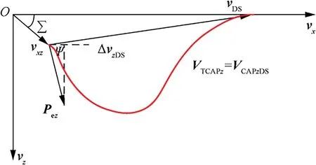
Fig.6 Lateral SLEM.
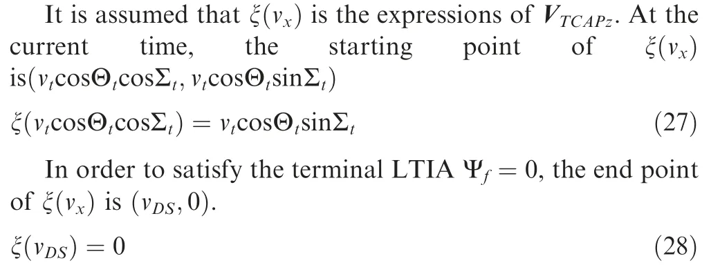
To ensure that the local yaw angle Ψ is continuously differentiable at the connection point v=v,the derivative of ξ(v) at the end point is (v,0).

In order to guarantee that the velocity capability attributed to thrust in the lateral plane is completely exhausted when vis reached,we have

Similar to Section 3.2,the lateral displacement Δzattributed to Vfrom the current point to the terminal is

3.4.Level-flight phase and line part VTCAPL design

V
Since the terminal LTIA and LTAA are required to be zero,the initial and end point of Vshould be (v,V).Therefore,Vcan be decomposed as

where Vand Vare the longitudinal and lateral velocity capabilities attributed to the thrust during the levelflight phase.
In order to guarantee that the velocity capability attributed to thrust is completely exhausted when the terminal velocity vis reached,we have

where Vand Vare the length of Vand Vrespectively.
V
Similar to Section 3.1,when v<v≤v,the altitude increment ΔHattributed to Vfrom the current point to Point D is

3.5.Solution of VTCAPy and VTCAPz
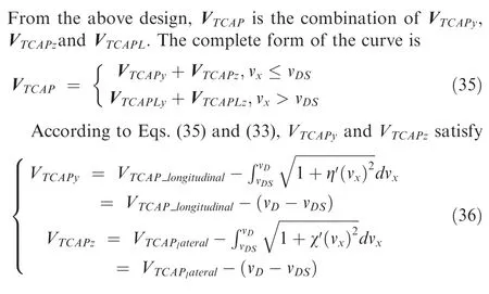
According to Eq.(5), Vcan be calculated in real time.Therefore,Vand Vare determined by v.The thrust vector drives the velocity vector along Vand the velocity capability attributed to gravity during this process is V.Therefore
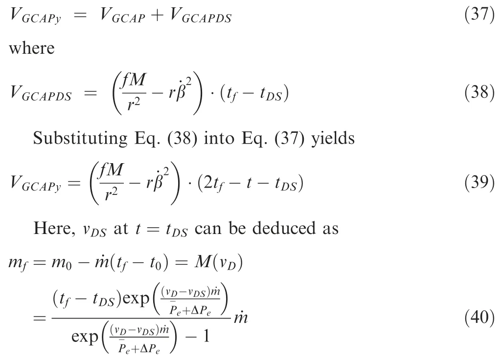
According to Eq.(34),the total altitude increment ΔHattributed to Vis

Then,ΔHcan be determined as

Thus,when v≤v,the terminal point (v,V),the altitude increment constraint ΔHand velocity capability constraint Vare all functions of v.In other words,these constraints are uniquely determined by v.
According to Eqs.(15)-(18),Eq.(26) and Eqs.(27)-(31),the velocity capability curve(v) and ξ(v) should satisfy
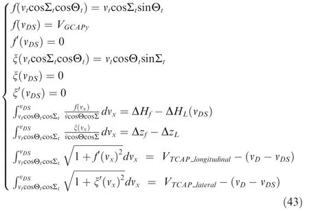
Since both of the velocity vector and position vector should be in the longitudinal plane at the terminal time,the lateral displacement and the lateral velocity due to lateral maneuver should return to zero,that is Δz=0 and v=0.
Remark 1.(v)ξ(v).(43).(v)ξ(v).(43).(43)..(43).,.,(v)ξ(v).

The number of unknowns in Eqs.(44) and (45) equals the number of equations in Eq.(43).From the above mathematical manipulations,the ascent energy management guidance problem can be converted into an equations-solving problem.Especially for the altitude and lateral displacement constraints,through designing the velocity capability curves as two splineline forms,the altitude and lateral displacement functions can be creatively transformed into functions of the spline-line parameters.Then the altitude and lateral displacement constraints can be satisfied by computing the parameters in Eq.(43).By this way,the guidance commands can be obtained rapidly by solving these equations with the existing mathematical methods.
Since the increment of v is small enough when calculating the integral,[,,,,,,,,,]. So we can approximate V andV with the value of[,,,,,,,,,]that[,,,,,,,,,] in this step..
3.6.Parameters determination of f(vx) and ξ(vx)
After the algebraic Eq.(43) about curve parameters are obtained,the solution of the equations is studied in this section.It is assumed that the velocity,altitude,and LTIA are measurable at any time during the flight.Therefore,Eq.(43)is a system of nonlinear equations with respect to[,,,,,,,,,].
In Eq.(43),
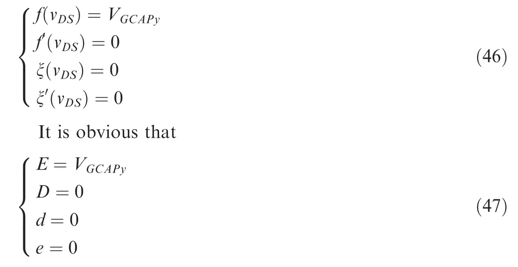
Therefore,Eq.(43) can be reduced to
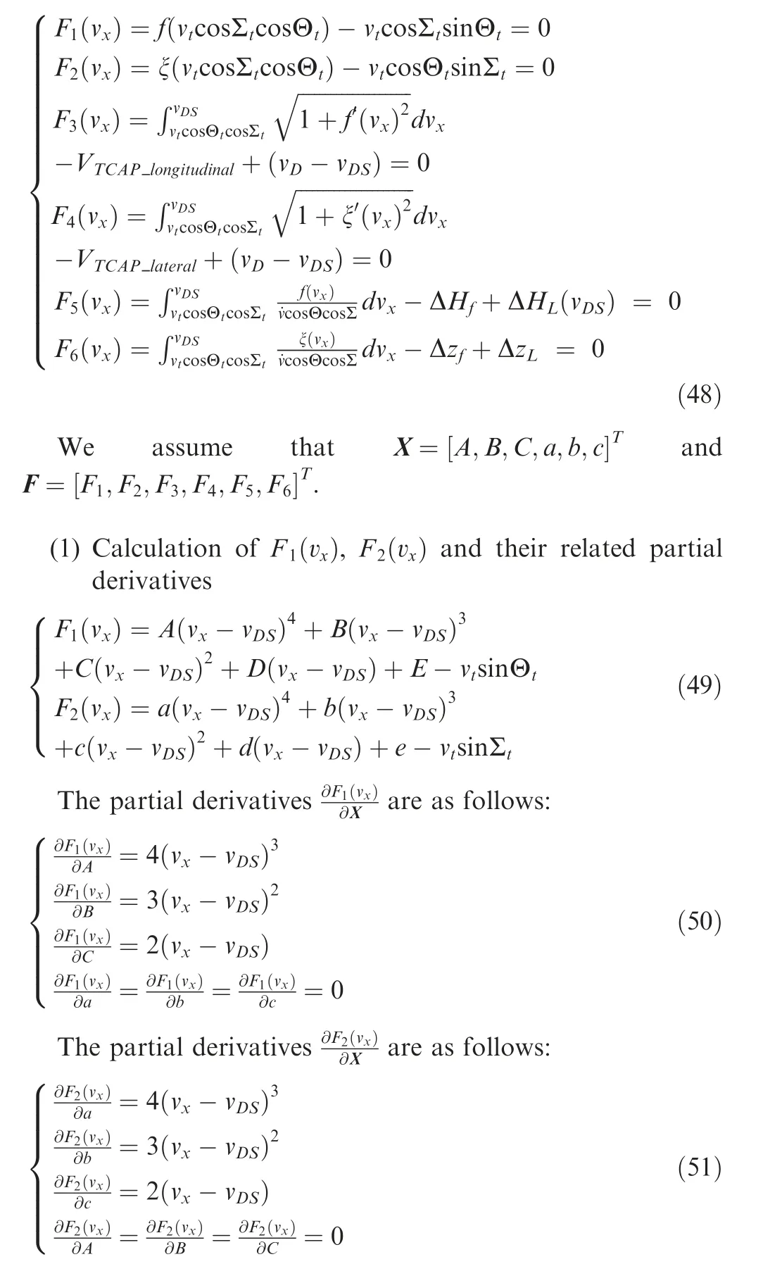
(2) Calculation of F(v),F(v) and their related partial derivatives
Due to the high orders of(v) and ξ(v),it is difficult to calculateandanalytically.For quick and easy calculations,numerical integration is approximated by using Simpson’s formula.
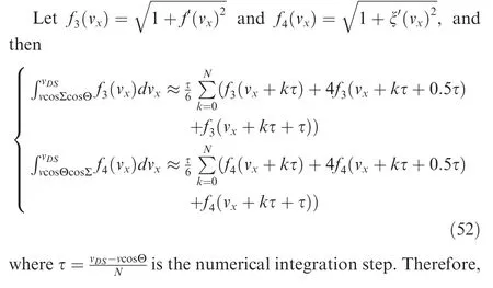

Then the partial derivatives of(v) with respect to X are as follows:
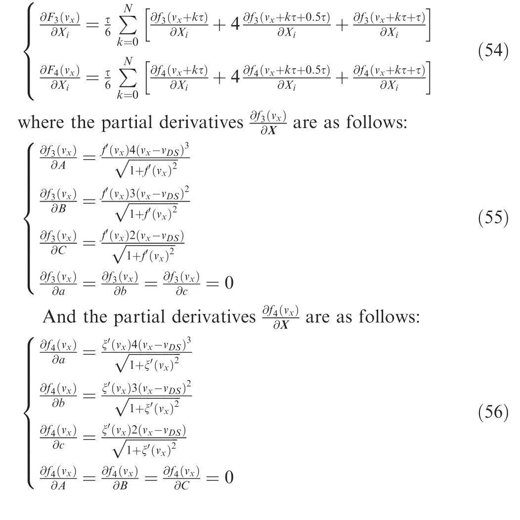
(3) Calculation of F(v),F(v)and their related partial derivatives
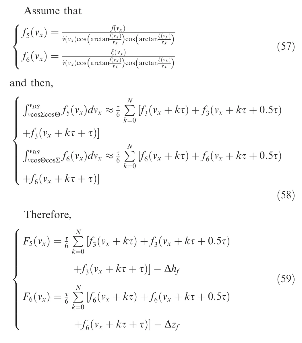
Then the partial derivatives of(v) and(v) with respect to X are as follows:
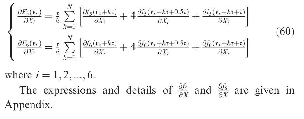
Remark 3..,.,:


After obtaining the curve of Vand V,the LPA and LYA commands closed-loop are established in Fig.7.To make the velocity vectors track Vand V,the local vertical error e,lateral velocity error e,LPA errorand LYA errorare taken as the feedback control variables.Then the rates of change of the LPA and LYA are taken as the control variable as follows:
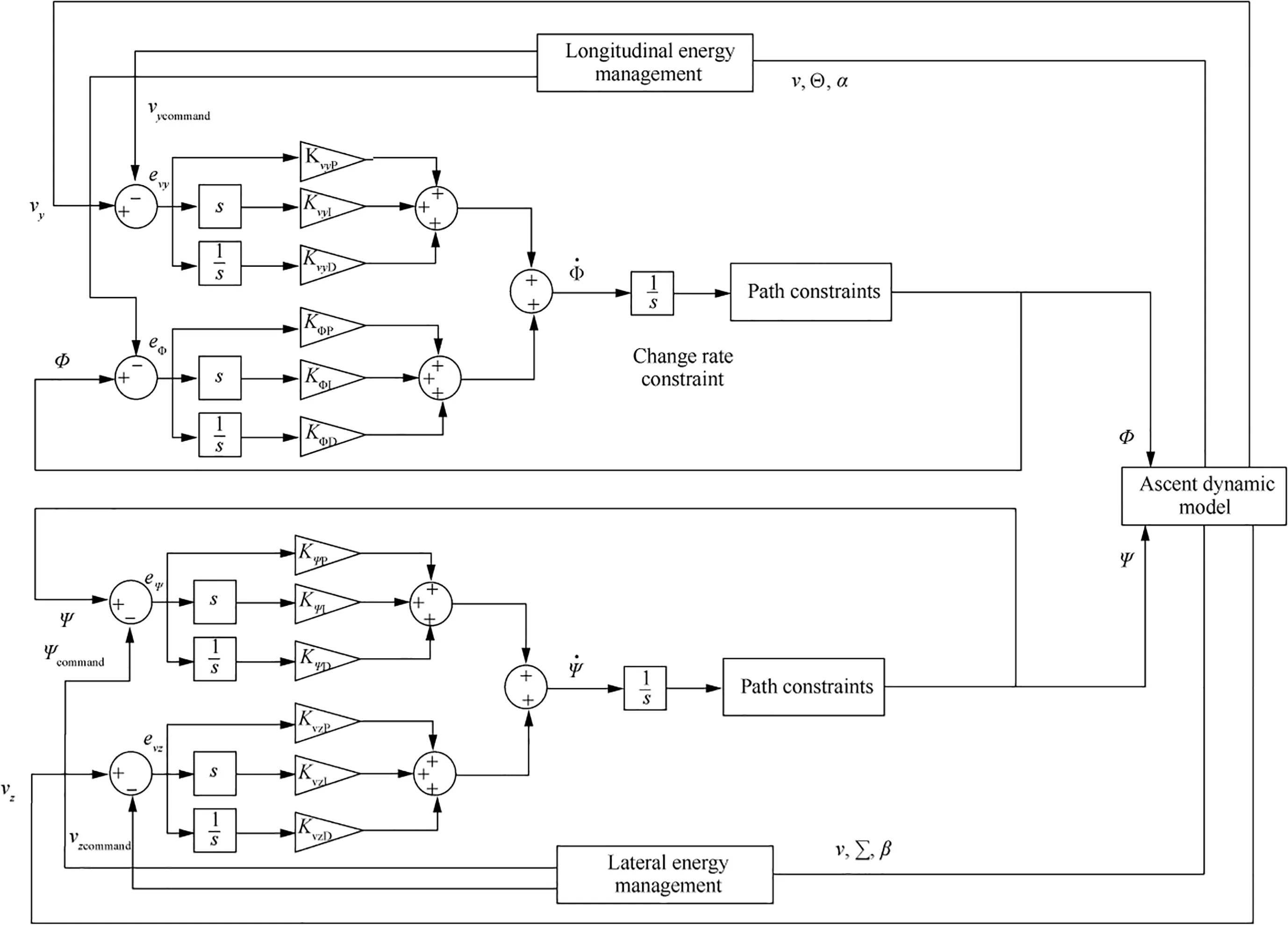
Fig.7 LPA and LYA command closed-loop model.

Then the rate of change of the LPA and LYA are taken as the control variable as follows:

where K,K,K,,,,K,K,K,,,are the coefficients of the corresponding PID controller.If the coefficients are selected properly,the actual velocity vector tracks Vand Vwell.
3.7.Path constraints in energy management
During the actual flight progress,several path constraints should be satisfied all the time.In this paper,overload constraints and control variables amplitude and change rate constraints are considered.The following figure is a schematic diagram of velocity profile with these two constraints.The meaning of fand fwill be explained later.It can be seen that f(v) and f(v) form the region,and f(v) andf(v) form the region.The public areas ofandare.The actual velocity curve cannot exceed.is called the feasible boundary of(v).

Once the theoretically velocity curve calculated in Section 3.6 goes beyond,the actual curve(v) should be modified to boundary of.In addition,the modification of ξ(v)is similar to(v).
To avoid the structure of the vehicle damaged with a highspeed turn,it is necessary to restrict the normal overloads.According to the definition of overload,gravity and thrust are decomposed along and perpendicular to the velocity defection in the longitudinal and lateral planes.The vertical and horizontal normal overloads are expressed as

The overload constraints during flight are

The boundary conditions of Eq.(66) are

Then the solution of boundary conditions can be divided into the following four cases:
(a)Φ-Θ>0 and Ψ-Σ>0,(b) Φ-Θ>0 and Ψ-Σ<0,(c) Φ-Θ<0 and Ψ-Σ>0,(d)Φ-Θ<0 and Ψ-Σ<0.
Let us take Case (a) as an example:
According to Eq.(65),the following equations are satisfied when the overload limits are reached.

Assume that Ω=sinΦ and Ω=sinΨ,and Eq.(68)can be written as

Φ and Ψ can be obtained iteratively by Eq.(69)using Newton method.
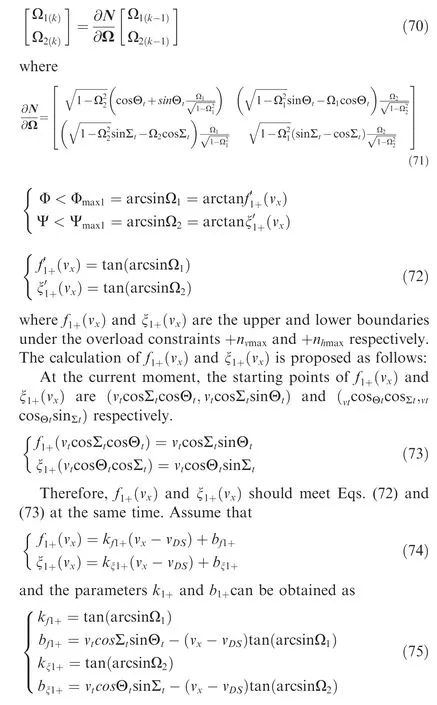
In actual flight,(v)and ξ(v)can be calculated in real time.The expressions of(v) and ξ(v) become

Similarly,,ξ,,,ξand ξare the upper and lower boundaries in the other three corresponding conditions and can be calculated online as Case (a).
α
The change rate and maximum amplitude constraints during flight are
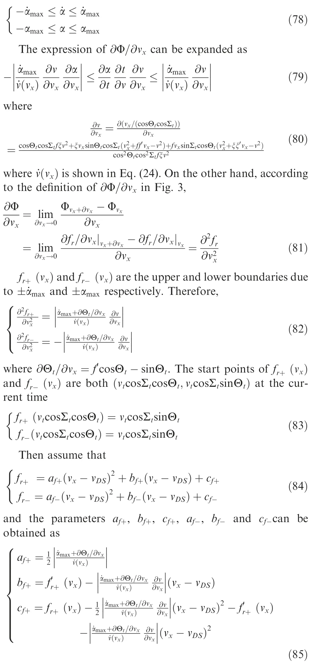
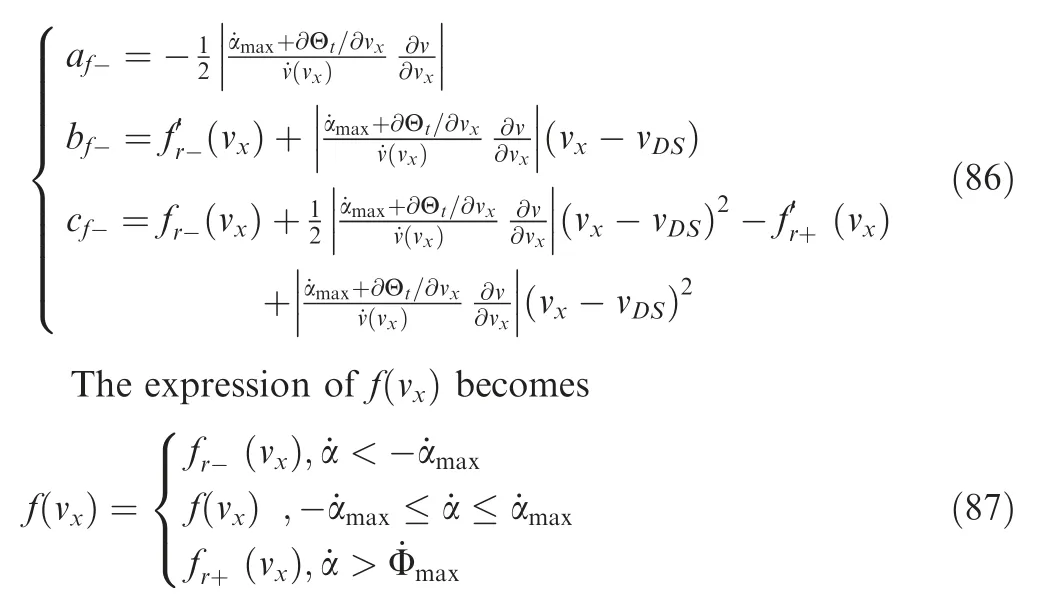
Similarly,the change rate constraints of β can be processed as α.
α
Energy management algorithm usually causes a large additional steering angle to dissipate the excess energy.The amplitude of the angle of attack needs to be limited

The overload constraint during flight is

According to Eq.(65),the following equation is satisfied when the overload limit is reached.
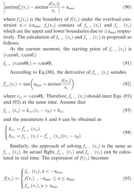
Similarly,the maximum amplitude constraints of β can be processed as α.
3.8.Robust energy management with uncertainties
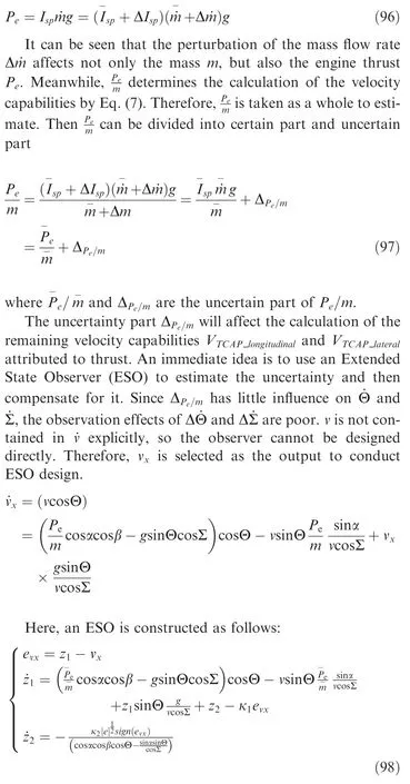
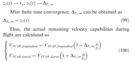
The process of rocket ascent is often accompanied by parameter uncertainties,among which the thrust perturbation has a great influence.If Vis still designed according to the nominal parameters in the case of uncertainties,the terminal states will not satisfy the constraint conditions.In this paper,the uncertainty of specific impulse and mass flow rate is considered.Therefore,the actual engine thrust can be written as

4.Simulations
In this section,several examples are provided to assess the effectiveness of the proposed SLEM method.The simulations are carried out in the VS2013 software environment.All numerical results are obtained on a desktop with Intel Core i7-3470 3.2 GHz.
4.1.Rocket model and simulation conditions
As a carrier of transportation,the rocket transports the load to a specified altitude at a certain speed in a specific attitude.Different flight missions require different terminal altitudes and velocities.In most missions,the terminal LTIA is required to be zero.The background considered in the example is the third stage of a multi-stage solid rocket.Multiple terminal constraints are desired to be satisfied in the ascent EM guidance.Initial conditions and parts of terminal conditions of the ascent task are given in Table 1.
4.2.Results of several energy management tasks with SLEM
In this section,some simulations are presented to verify the proposed SLEM algorithm.The algorithm is to program the velocity capability curve online and generate command input during a guidance period.To verify the applicability of the algorithm,the terminal velocity constraint varies from 7000/to 7600/.The initial condition and other terminal constraints are shown in Table 1.In addition,the robustness of SLEM algorithm with uncertainty and the performance under path constraints are tested.
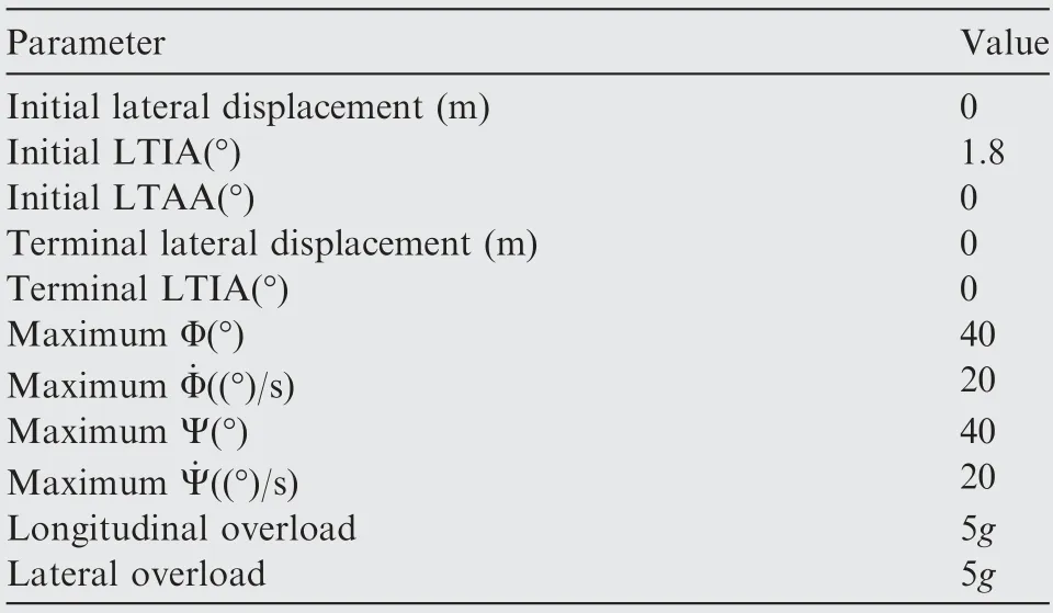
Table 1 Initial conditions and constraints.
The results of the energy management task of a fixed terminal altitude and various terminal velocities are shown in Fig.9.From the h-v and LTIA profiles in Fig.9,the SLEM algorithm achieves the terminal altitude,velocity and LTIA constraints of the 4 different energy management tasks with high precision.As shown in Figs.9(c)-(f),the terminal LTIAs,LTAA,α and β are all converged to zero.Due to the line segment design of the level-flight phase in the SLEM algorithm,it keeps the LPAs and LYAs being 0 for a few seconds,which realizes the condition of releasing payload at the end of the launch phase.It can be seen that angle of attack profiles are affected by overload,amplitude and change rate constraints in Fig.9(e).Figs.9(g)-(j) show the overload and change rate profiles of α and β.It can be seen that the overload and change rate constraints are satisfied during the whole progress.From the LTAA-t profiles in Fig.9(d),the LTAA converges to zero when the velocity reaches the terminal constraint value.Meanwhile,from the LTAA-t profiles in Fig.9(d),the terminal LTAAs Σ which approach to 0 indicate that the lateral velocity vconverge to 0 at the terminal time.


where ε,ε,ε,ε>0.In this simulation,let ε=ε=5 and ε=ε=20.This causes the sharp variation rate of in Figs.9(e)-(g).

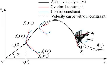
Fig.8 Velocity profile with path constraint.
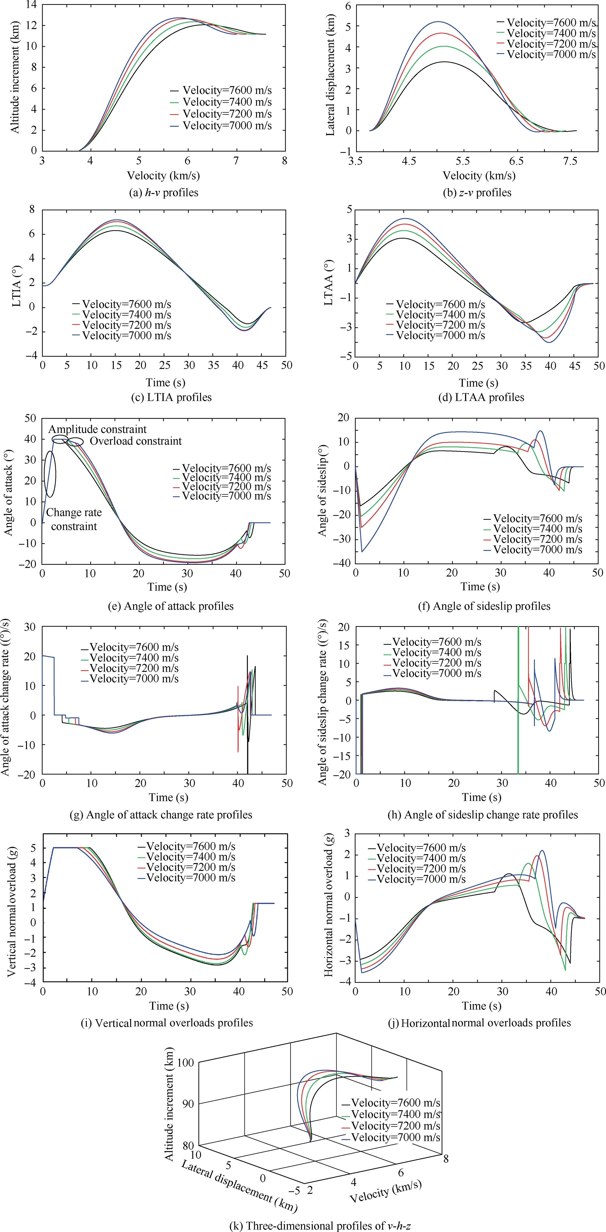
Fig.9 Simulation results for fixed altitude with various velocities.
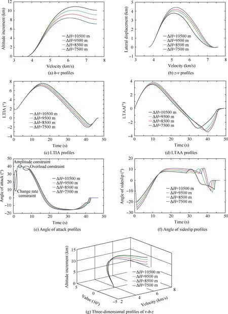
Fig.10 Simulation results for fixed altitude with various velocities.
The average convergence time of the SLEM in each guidance period for the above different simulated tasks is shown in Table 2.It shows the total average convergence time,average convergence time for solving(v)and ξ(v).It can be seen that the convergence time of the SLEM can satisfy the real-time requirement of the energy management guidance and most of the calculation time is spent on solving(v) and ξ(v).
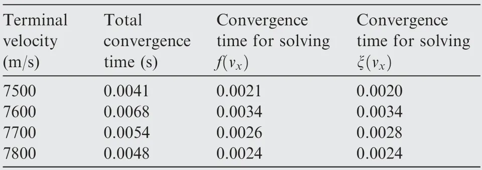
Table 2 Average convergence time of SLEM in each guidance cycle for different tasks.

Table 3 Terminal errors of SLEM with thrust perturbation dispersion.
In this section,the reachable area of energy management with the SLEM algorithm is simulated.As shown in Fig.11,the profiles obtained by Monte Carlo simulation with different terminal velocity and altitude constraints form the reachable area of the SLEM.By GPOPS,four limited points form the reachable area roughly and energy management is performed only in the longitudinal plane.The 4 limited points are(7000 m/s,13500 m),(7850 m/s,7500 m),(7050 m/s,13500 m) and (7800 m/s,13500 m).From Fig.11,it can be known that the reachable area with the SLEM is larger than the maximum reachable area optimized with GPOPS in longi-tudinal plane.The reachable area of 3D-SLEM is larger than that only in longitudinal plane by 2D-GPM,because it introduces the lateral plane velocity exhaustion,which enhances the capability of energy management and enlarges the reachable area.
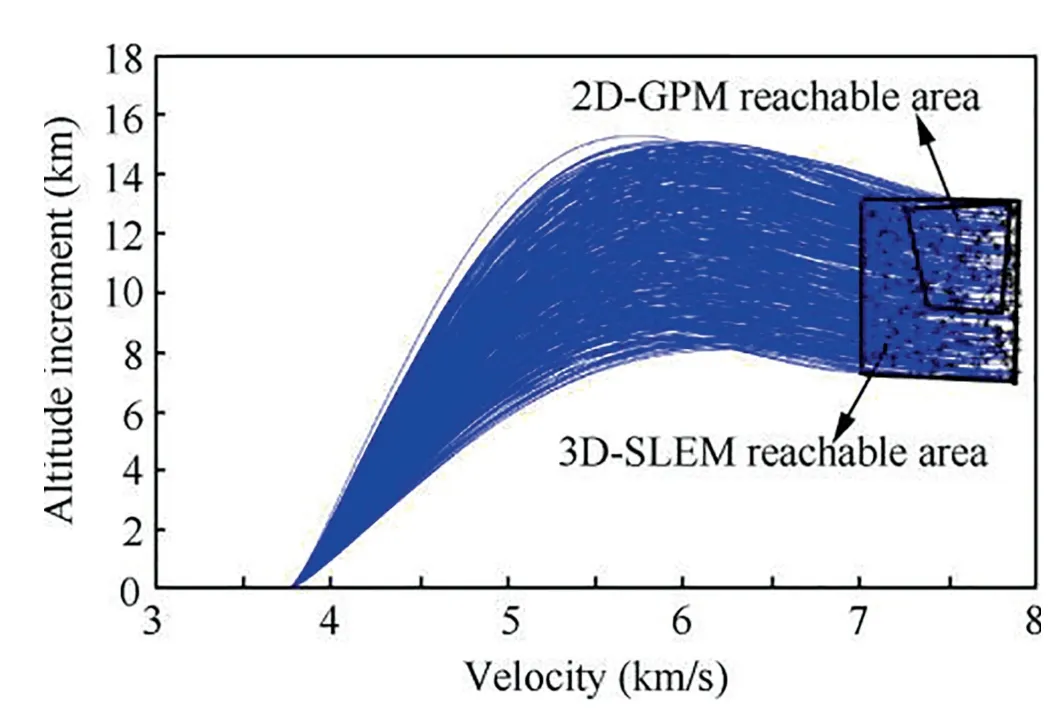
Fig.11 Comparison of reachable area between SLEM and GPM.

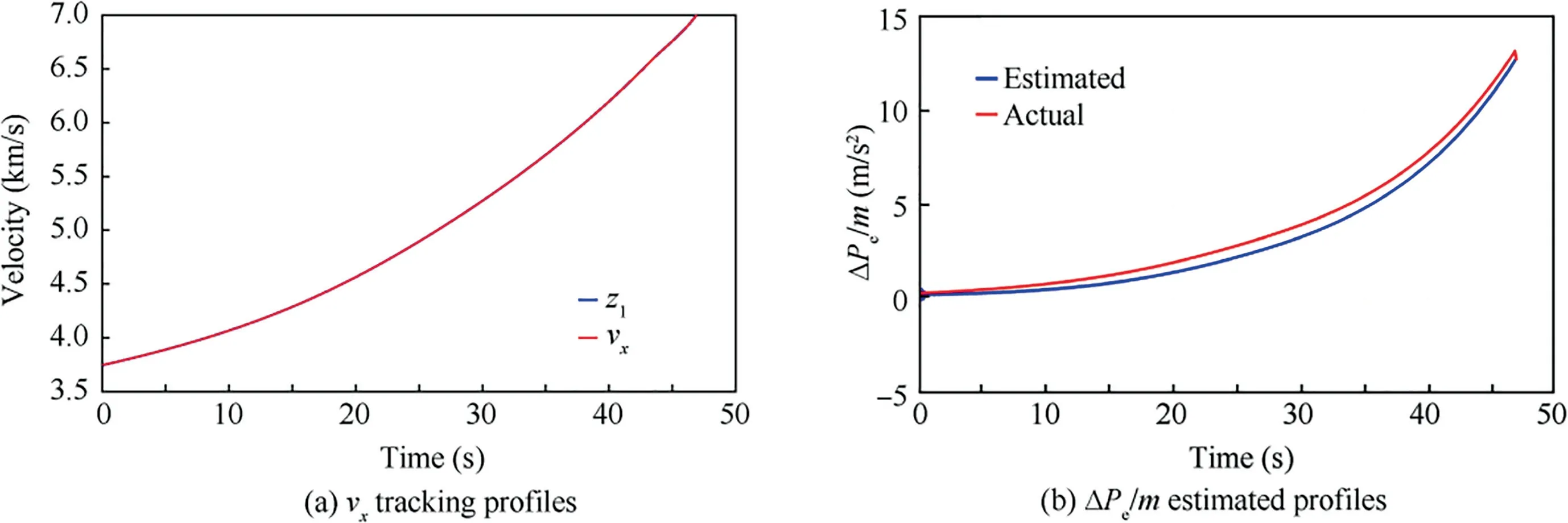
Fig.12 Tracking profiles of ESO.
Fig.13 shows theandprofiles with and without compensation respectively.It can be seen that the terminal altitude and velocity error are obviously large,and the lateral displacement does not converge to zero without uncertainties compensation.In the case of uncertainties compensation,the errors of terminal altitude and velocity can be guaranteed within the allowable range.
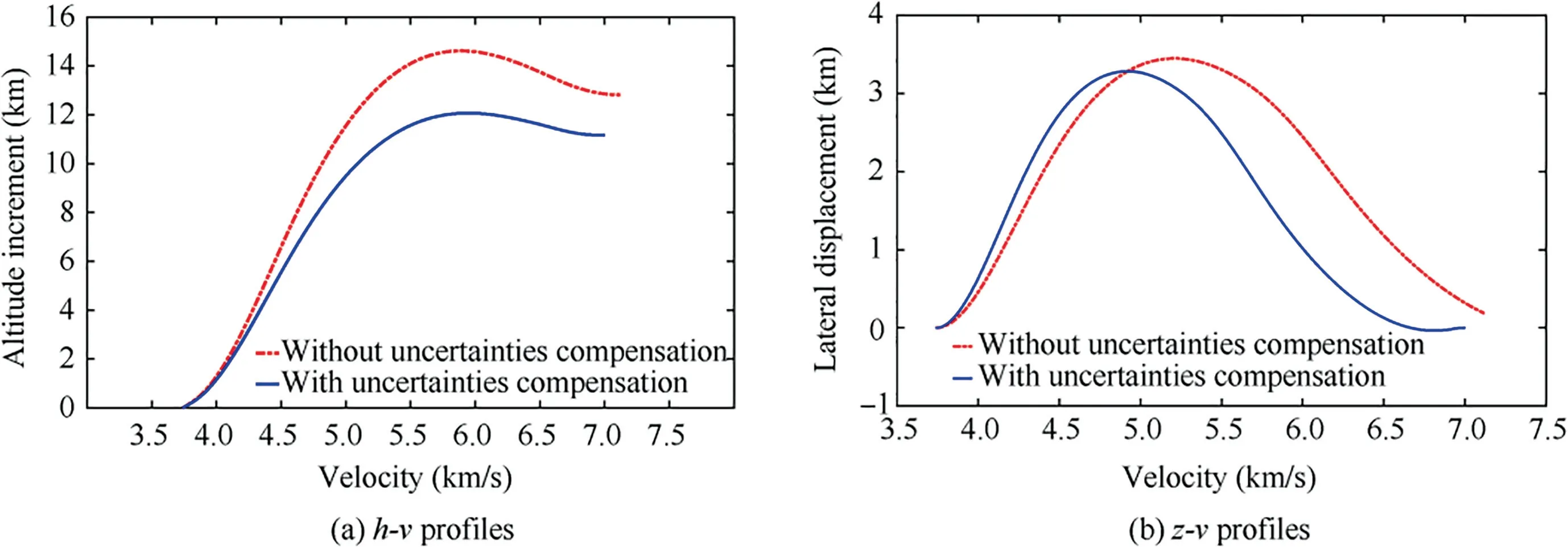
Fig.13 Simulation results with/without uncertainties compensation.

Fig.14 Simulation results for fixed altitude and velocity with perturbations.

First,the altitude,lateral displacement and velocity curves along 500 dispersed ascent trajectories are presented in Figs.14(a)and(b).It can be seen that although the uncertainty values are different,all the ascent trajectories satisfy the terminal altitude,velocity and LTIA constraints accurately.The ranges of terminal state errors are shown in Table 3.Figs.14(c) and (d)show the distribution of terminal velocity,altitude and LTIA.The terminal errors meet the accuracy index.
4.3.Comparison among SLEM,AEM and SEM
In this section,the comparison of SLEM with AEM and SEM 1is shown in Fig.15.In the AEM algorithm,the standard trajectory is tracked in longitudinal plane to eliminate altitude deviation due to lateral coupling.And the velocity dissipation is achieved by AEM.The desired terminal velocity is 7000 m/s and the desired terminal altitude is 11500 m.From theandprofiles,it can be seen that all the three algorithms can achieve the desired terminal velocity.The SLEM and AEM can achieve the desired terminal altitude.However,the amplitude of sideslip angle and overload generated by AEM method are significantly larger.It is because the velocity dissipation is completely dependent on the lateral plane,which leads to a wide range of sideslip angle maneuvers.In the SLEM algorithm,it distributes the velocity dissipation into two planes and assumes the velocity dissipation together.Therefore,the algorithm generates smaller angles of attack and sideslip.In other words,compared with the two-dimensional energy management algorithm,this algorithm enhances the ability of energy management.Table 4 presents the values and errors of the terminal states when using the SLEM,AEM and SEM with the same initial conditions and terminal constraints.From this table,it is obvious that the solution of the SLEM is more accurate by comparing the line of error.Meanwhile,the data in Table 4 explain the conclusions of Fig.15.

Table 4 Terminal errors of comparison among SLEM,SEM and AEM.
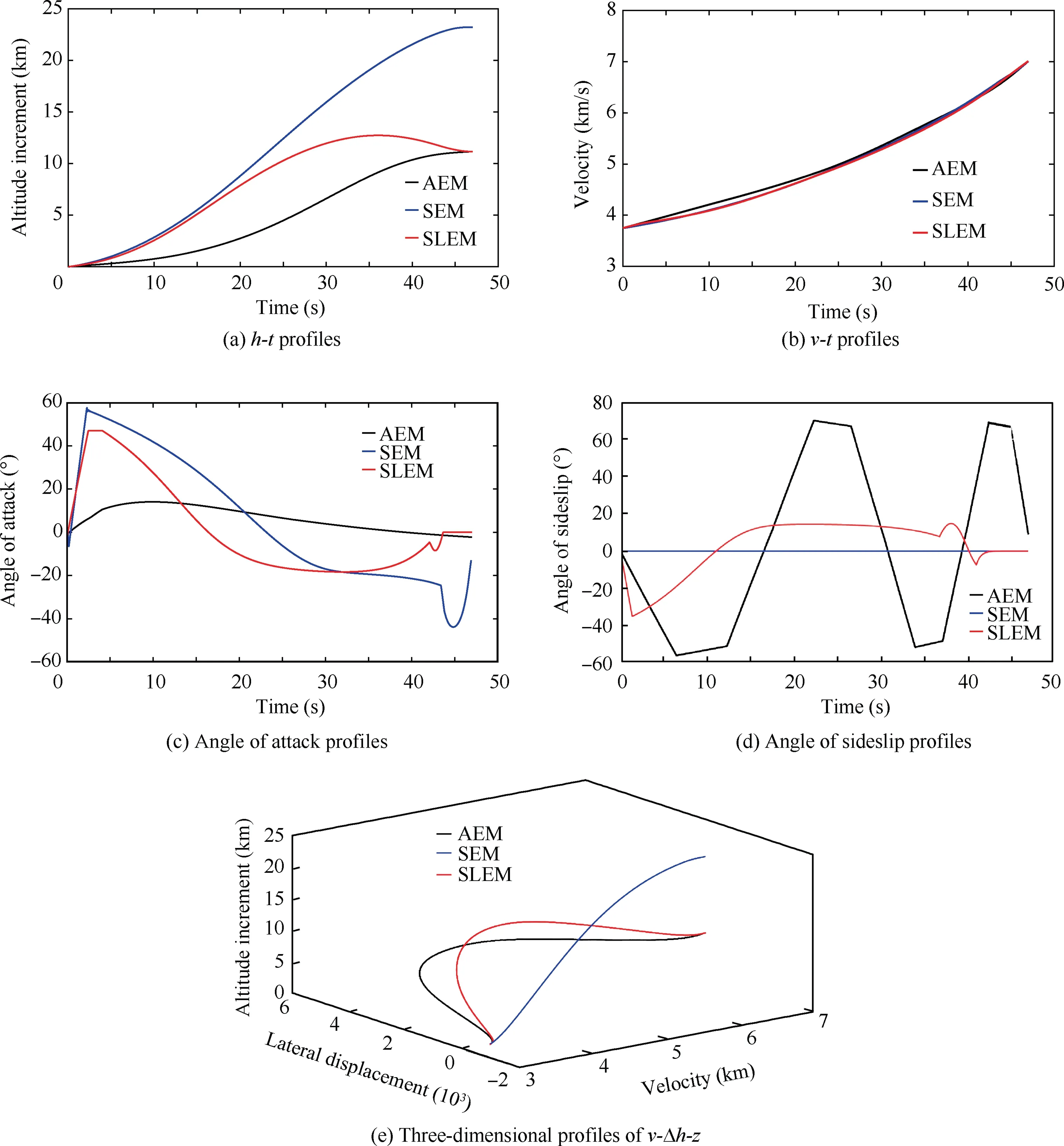
Fig.15 Comparison among AEM,SEM and SLEM.
5.Conclusions
This paper develops an online algorithm with energy management technique,which is applicable to the ascent stage of solid rocket by fuel exhaustion.The simulation results show that the proposed SLEM algorithm performs well and can be implemented in ascent energy management guidance problems.
The main contributions of this paper are summarized as follows:
(1) The proposed algorithm in this paper converts all the terminal state constraints to several nonlinear equations constraints.It satisfies terminal velocity,LTIA and altitude constraints with high precision,which overcomes the shortcoming of traditional algorithms that cannot meet the altitude constraints.Meanwhile,this algorithm achieves the level flight requirement at the end of ascent guidance.
(2) The proposed SLEM algorithm combines the longitudinal and lateral plane.It extends the energy management to the three-dimensional space to expand the adjustable range of terminal velocity and altitude.
(3) The path constraints are added in this paper,which considers the capability of actuator and guarantees the structure security.And the energy management task can still be completed accurately under the path constraints.
(4) The algorithm is further extended to robust energy management with uncertainties.The terminal constraints are accurately satisfied with perturbations.
(5) An approach is proposed,which converts the problem of solving a space velocity capability curve into that of solving two plane velocity capability curves.It eliminates the effect of lateral maneuvers on altitude and reduces the order of the spline curves.Moreover,when the terminal reaches the specified altitude and velocity in longitudinal plane,the lateral displacement and velocity converge to zero.
The authors declare that they have no known competing financial interests or personal relationships that could have appeared to influence the work reported in this paper.
This study was supported by th National Natural Science Foundation of China (Nos.61627810,61790562 and 61403096).
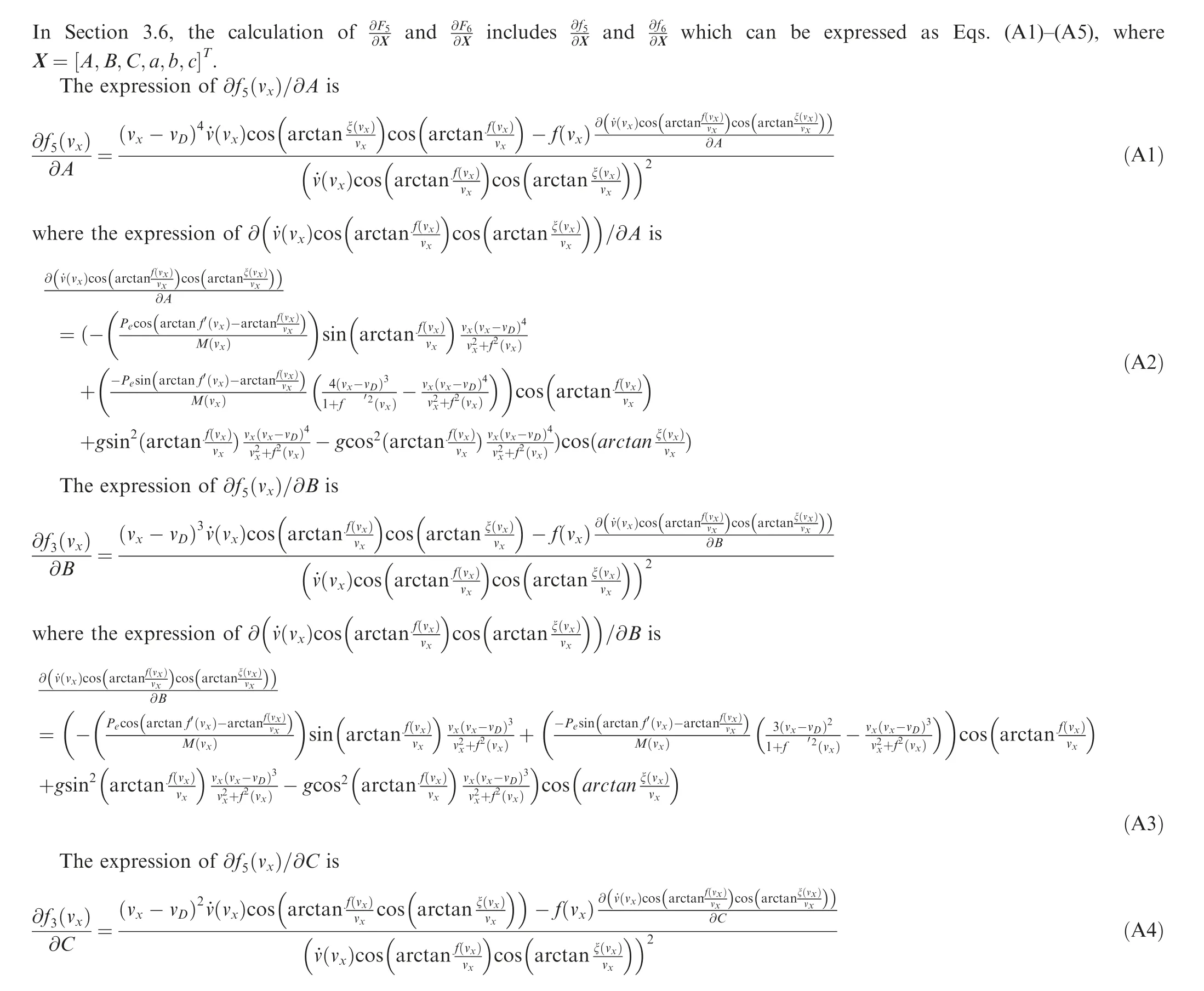
Appendix A.Partial derivative of f and f with respect to X

 Chinese Journal of Aeronautics2022年2期
- Chinese Journal of Aeronautics的其它文章
- Surface morphology characterization of unidirectional carbon fibre reinforced plastic machined by peripheral milling
- Effect of cooling strategies on performance and mechanism of helical milling of CFRP/Ti-6Al-4 V stacks
- Electrochemical cutting of mortise-tenon joint structure by rotary tube electrode with helically distributed jet-flow holes
- Positioning error compensation of an industrial robot using neural networks and experimental study
- Vibration coupling effects and machining behavior of ultrasonic vibration plate device for creep-feed grinding of Inconel 718 nickel-based superalloy
- Formability enhancement in hot spinning of titanium alloy thin-walled tube via prediction and control of ductile fracture
