Vibration coupling effects and machining behavior of ultrasonic vibration plate device for creep-feed grinding of Inconel 718 nickel-based superalloy
Yng CAO ,Yejun ZHU ,Wenfeng DING,* ,Yutong QIU ,Lifeng WANG ,Jiuhu XU
a National Key Laboratory of Science and Technology on Helicopter Transmission,Nanjing University of Aeronautics and Astronautics,Nanjing 210016,China
b College of Engineering,Nanjing Agricultural University,Nanjing 210032,China
c College of Aerospace Engineering,Nanjing University of Aeronautics and Astronautics,Nanjing 210016,China
KEYWORDS Apparent elastic method;Machining behavior;Ultrasonic vibration-assisted grinding;Ultrasonic vibration plate device;Vibration coupling effects
Abstract Ultrasonic vibration-assisted grinding(UVAG)is an effective and promising method for machining of hard-to-cut materials.This article proposed an ultrasonic vibration plate device enabling the longitudinal full-wave and transverse half-wave (L2T1) vibration mode for UVAG.The characteristics of two-dimensional coupled vibration in different directions were analyzed on the basis of apparent elastic method and finite element method.Furthermore,a correction factor was applied to correct the frequency error caused by the apparent elastic method.Finally,the comparative experiments between the conventional creep-feed grinding and UVAG of Inconel 718 nickel-based superalloy were carried out.The results indicate that the apparent elastic method with the correction factor is accurate for the design of plate device under the L2T1 vibration mode.Compared with the conventional creep-feed grinding,the UVAG causes the reduction of grinding force and the improvement of machined surface quality of Inconel 718 nickel-based superalloy.Furthermore,under the current experimental conditions,the optimal ultrasonic vibration amplitude is determined as 6 μm,with which the minimum surface roughness is achieved.
1.Introduction
Inconel 718 is one of the most popular nickel-based superalloys due to its high temperature strength,anti-oxidation,corrosion resistance and high toughness.It is a promising metallic material used under extreme temperate conditions especially in the aviation and aerospace industry.However,due to the poor machinability of Inconel 718,the large grinding force is commonly produced and lots of heat is easily generated between the abrasive wheel and workpiece in the conventional creep-feed grinding process with large depth of cut.This phenomenon further leads to the thermal damage,poor workpiece surface quality and severe tool wear.Therefore,the conventional creep-feed grinding method of Inconel 718 nickel-based superalloy needs to be improved greatly.
The ultrasonic vibration-assisted grinding (UVAG) is an impactful hybrid machining process for various difficult-tocut materials.Due to the lower grinding force and better machined surface quality,the UVAG has been widely applied to grind nickel-based superalloy,titanium alloy,brittle ceramicsand composites materials.For instance,Bhaduri et al.worked on the UVAG of γ-TiAl intermetallic with a special ultrasonic sonotrode.The maximum 10%reduction of workpiece surface roughness,8% increase of subsurface microhardness and fewer defects were obtained.Yang et al.studied the grinding force and machined surface quality in UVAG of ZrOceramics.The results indicated that the normal and tangential grinding forces in UVAG were 34.32%and 37.64% lower than those in the conventional grinding (CG),respectively.Li et al.studied the material removal mechanism in UVAG of SiC ceramics.Four different states of material removal mechanism had been observed in the varied-depth nano scratch process,and the values of critical depths of the four state transitions were attained.Ding et al.proposed that the UVAG was a competitive method to machine the C/SiC composites material because the ultrasonic vibration could effectively reduce the breakages of fibers.
At present,the ultrasonic vibration can be generated on either tool or workpiece.For example,Zhao et al.proposed a special grinding wheel to manufacture Nano-ZrOceramics,enabling an ultrasonic-assisted elliptical vibration of tool.Teimouri et al.proposed a novel tool for ultrasonic vibrationassisted turning of 7075 aluminum material.The results indicated that the high frequency vibration could reduce the cutting force and the surface roughness.However,the vibration uniformity was commonly poor when the ultrasonic vibration was generated on the cutting tool of large size.Hence,the cutting speed,which was helpful to improve the machining efficiency,was generally limited.
The workpiece ultrasonic vibration facilitates the utilization of UVAG when the tool has a large size or a complex structure,which render such kind of method a more promising application prospect.In recent years,several studies have highlighted the importance of workpiece ultrasonic vibration method.Han et al.developed a sonotrode with normal directional ultrasonic vibration achieving 15% cutting force reduction.Tawakoli and Azarhoushangdesigned a tangential ultrasonic vibration equipment to realize UVAG of 100Cr6 steel and ceramic matrix composites.Lu et al.designed a three-dimensional (3D) ultrasonic vibration platform.The special T-shaped flexure hinge was utilized to connect the platform and the base,achieving tunable characteristics of ultrasonic vibration mode.The 3D elliptical workpiece ultrasonic vibrations were applied in the processing of CFRP composites by Wang et al.The results suggested that the cutting force and surface roughness could be obviously decreased by the 3D elliptical ultrasonic vibrations.
In the previous work,Cao et al.have suggested that the ultrasonic vibration plate device under the longitudinal fullwave and transverse half-wave (L2T1) vibration mode was of high performance and efficiency for UVAG.The apparent elastic method and Rayleigh method were appropriate to reveal the relationship between plate device size and vibration characteristics.However,as the apparent elastic method regards the material property as anisotropy in vibrating,which is not consistent with the actual situation,the resonant frequency error is produced and has not been studied yet.Meanwhile,the influence of the two-dimensional (2D) vibration coupling effects on the L2T1 vibration mode has not been analyzed in detail.These problems seriously limit the application of ultrasonic vibration device in creep-feed grinding of Inconel 718 nickel-based superalloy.
As a result,the purpose of the present research is as follows:(1) The influence of vibration coupling effect on vibration characteristics of plate is analyzed,and the optimal coupling coefficient enabling the excellent vibration mode for UVAG is attained.(2) A correction factor is applied to diminish the error of resonant frequency caused by the conventional apparent elastic method.(3) The performance of the ultrasonic vibration plate device with the optimal coupling coefficient and the frequency correction factor is tested through the comparative experiments between CG and UVAG.On the basis of the purpose,the article mainly consists of two parts.The first part is about the analysis of vibration coupling effects,which attains the value of optimal coupling coefficient and frequency correction factor.The second part focuses on the performance evaluation of the ultrasonic vibration plate device with the optimal coupling coefficient and frequency correction factor through the UVAG experiments.
2.Working principle of the UVAG system
The UVAG system is composed of an ultrasonic vibration plate device,an ultrasonic generator,an ultrasonic transducer,a horn,four legs and a grinding wheel,as schematically shown in Fig.1.The ultrasonic generator provides electric signals of high-frequency to the ultrasonic transducer.The ultrasonic vibration,which is generated by the ultrasonic transducer,drives the ultrasonic vibration plate device to operate under a special vibration mode.The plate device is installed on the legs in the wave nodes to minimize energy loss.The workpiece is directly bolted through the holes in the central area of the plate device for good transmitting of the ultrasonic energy.Finally,it achieves the uniform-directional ultrasonic vibration in the workpiece.
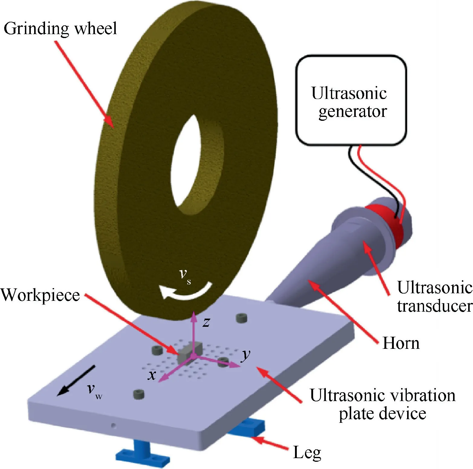
Fig.1 Ultrasonic vibration-assisted grinding system.
According to the Poisson’s effect,the longitudinal and transverse vibrations are generated simultaneously on the plate device.The vibrations in these two directions are coupled under the stable longitudinal full-wave and transverse halfwave (L2T1) vibration mode,as displayed in Fig.2.In the center of the plate device,the displacement in thedirection reaches the maximum value (Fig.2(a)) and the displacement in thedirection reaches approximate 0(Fig.2(b)),indicating that the-directional uniform vibration area is realized in the center of the plate device.
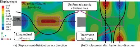
Fig.2 L2T1 vibration mode of ultrasonic vibration plate device.
As it is known,when the length and width of the plate are larger than 1/4 wavelength,the strain in the longitudinal direction is caused not only by the stress in the longitudinal direction but also by the stress in the transverse direction because of the Poisson’s effect.The longitudinal and transverse vibrations are coupled to each other orthogonally.Therefore,the vibration mode of plate is always complex and is affected by the geometric parameters(length and width).Accordingly,in the theoretical design of plate device,the coupling of vibration in two directions should be considered.
The apparent elastic method,which assumes that the material elasticity changes with the coupling of vibration,is an effective approach for large resonators design.However,the resonant frequency error occurs because the apparent elastic method considers the plate device material as anisotropic material.This phenomenon is not consistent with the actual situation.To fill this gap,a correction factor α is applied to correct the resonant frequency error,which can be written as:

whereandare the actual and theoretical resonant frequency,respectively.According to Eq.(1) and the conventional apparent elastic method,the frequency equation of the plate device is obtained as follows:

where land lare the length and width of plate device,respectively. kand kare the quantity of half-waves in theanddirections,respectively.As L2T1 vibration mode is adopted,kis 2 and kis 1 in this research.is the Poisson’s ratio,ρ is material density,is material elastic modulus.is the coupling coefficient which represents the vibration coupling level in theanddirections,=σ/σ.σand σare the internal stress in the plate device along theanddirections,respectively.When the coupling coefficient is positive,this phenomenon indicates that σ/σis positive in vibrating.Hence,the vibration phases in theanddirection are coincident.Adversely,when the coupling coefficient is negative,σ/σis negative and the vibration phases in theand y direction are reverse.Therefore,the displacement distribution of L2T1 vibration mode is determined by the coupling coefficient.The material of the plate device is 316L stainless steel,the detailed parameters of material are listed in Table 1.

Table 1 Material property of the plate device.39,40
3.Vibration coupling effects of ultrasonic vibration plate device
The purpose of this section is to analyze the vibration coupling effects and determine the optimal value of coupling coefficient firstly.Secondly,the resonant frequency error is analyzed and the value of frequency correction factor is determined.As the values of optimal coupling coefficient and frequency correction factor are attained,the ultrasonic vibration plate device can be designed accurately according to Eqs.(2) and (3).Finally,the effects of grinding wheel and workpiece on the ultrasonic vibration are analyzed additionally.
3.1.Influence of coupling coefficient on geometric parameters
On the basis of the apparent elastic method,the relationship among the geometric parameters of the plate device is shown in Fig.3.The theoretical ultrasonic frequencyis a constant value of 20 kHz in this case.It has been found that the plate device width decreases from 0.122 m to approximate 0,and the coupling coefficient increases from -5.04 to -0.01 with an increase of the plate device length from 0.160 m to the value of full-wavelength (0.250 m).When the plate device length is closed to the value of full-wavelength,the coupling coefficient and the plate device width are both closed to 0.This result indicates that the plate device operates like a long beam,which follows the one-dimensional (1D) vibration theorybecause the width is less than 1/4 wavelength.When the plate device length further increases from 0.266 m to 0.353 m,the coupling coefficient increase from 0.375 to 1.703,and the plate device width decreases from 0.263 m to approximate the value of half-wavelength.
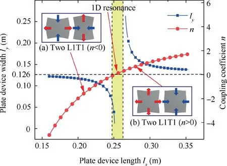
Fig.3 Relationship between geometric parameters (plate length and width) and coupling coefficient.
Additionally,it has been found that the plate device length and width are less than full-wavelength and half-wavelength respectively,when the value of coupling coefficient is negative.On the contrary,when the value of coupling coefficient is positive,the plate device length and width are larger than fullwavelength and half-wavelength,respectively.To further analyze the basic vibration mode of plate device,the L2T1 vibration mode is divided into two L1T1 vibration modes by symmetry.Similar to the L2T1 vibration mode,the L1T1 vibration mode is defined as the vibration mode of half-wave in both longitudinal and transverse directions.Hence,the L1T1 vibration mode is one of the basic vibration modes of plate.With the negative coupling coefficient,the plate device is under the basic vibration mode and the vibration phase of the adjacent edges is opposite (Fig.3(a)).Adversely,the positive coefficient indicates that the plate device is under another basic vibration mode and the vibration phase of the adjacent edges is same (Fig.3(b)).Consequently,the negative or positive coupling coefficient suggests that σ/σis negative or positive in vibration.This phenomenon indicates that two different kinds of basic vibration modes can be generated in the plate device according to the value of coupling coefficient.
3.2.Influence of coupling coefficient on vibration mode
Finite element method (FEM) is commonly utilized in the design of ultrasonic device and has been verified to be accurate enough for the calculation of vibration mode.In this work,the vibration mode is calculated through FEM by the Ansys Workbench software.Firstly,the geometric parameters of plate device were obtained through apparent elastic method.Then,the geometric model was established in the Ansys Workbench software and meshed into hexahedral elements with 8 nodes.The boundary conditions of plate device were free.The size of elements was 0.005 m.Finally,the L2T1 vibration mode and the actual resonant frequency were acquired through the modal analysis.As the actual drive force is not employed,the displacement calculated through the modal analysis is dimensionless.
The relationship between the coupling coefficient and thedirectional displacement distribution is displayed in Fig.4.Fig.4(a) shows the displacement distribution on the-axis when the displacement on the edge of-axis is set to be -1.With the negative coupling coefficient,the displacement distribution on the-axis is similar to a sine curve (Fig.4(b) and(c)).The wave peaks are generated in the center and at the ends on the-axis.When the coupling coefficient changes from-2.6 to-1.0,the displacement in the center of the plate device A(0,0)increases from 0.574 to 1.045,and the distance between two nodeschanges from 0.0712 m to 0.110 m.With the increase of the coupling coefficient from -1.0 to 0.4, A(0,0)decreases to 0.678 andincreases to 0.122 m.When the coupling coefficient is 0.5,an area achieving the uniform ultrasonic vibration is observed in the center of the plate device.This phenomenon suggests that a uniform workpiece ultrasonic vibration can be achieved when the workpiece is clamped in this area,as displayed in Fig.4(d).Under this condition,A(0,0) andare 0.899,0.20 m,respectively.When the coupling coefficient is 0.7,two peaks are observed in the center of plate device,as displayed in Fig.4(e).The vibration uniformity in the center is poor and the displacement of the point in the middle of two wave peaks is small (A(0,0)=1.31).
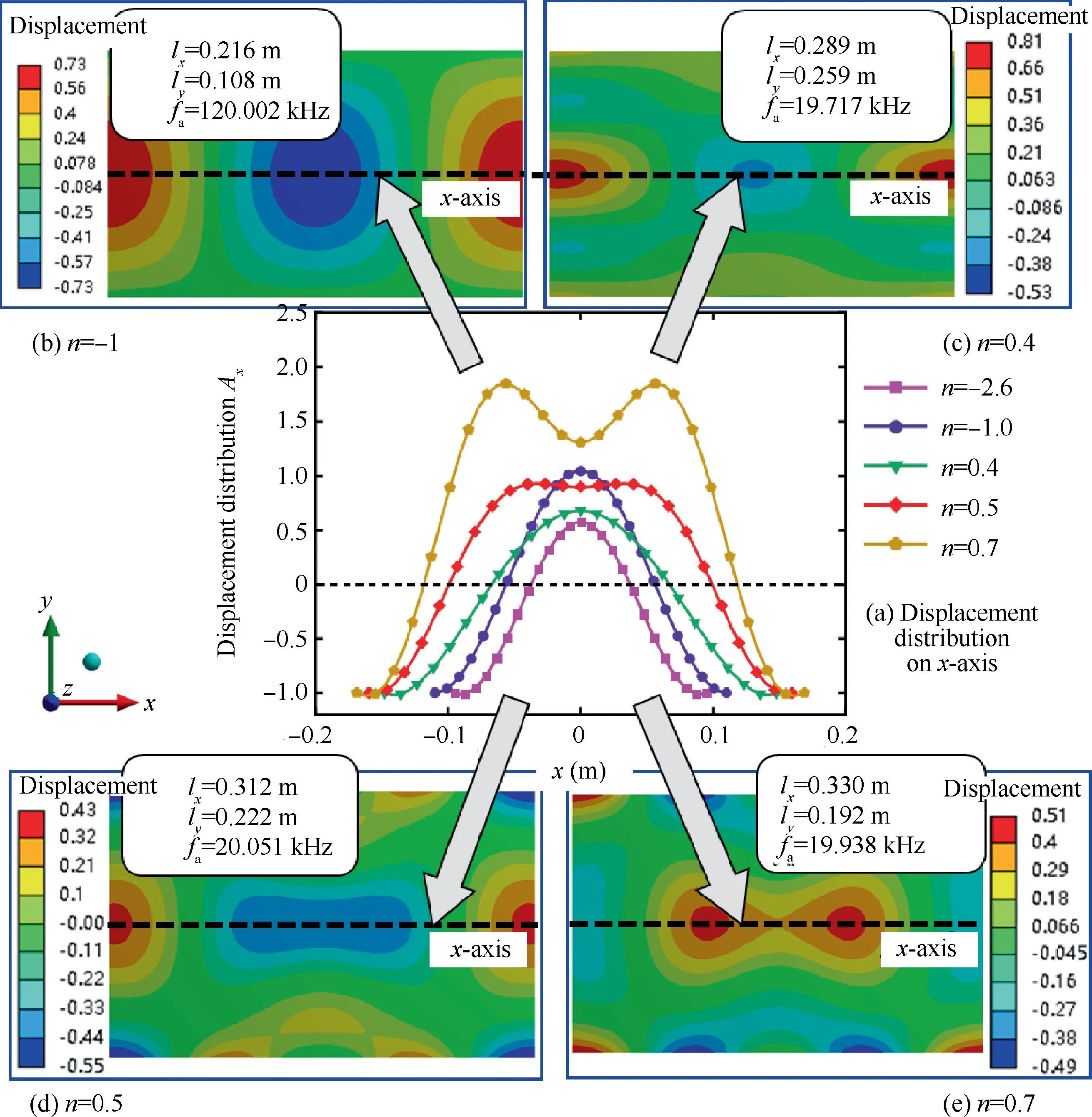
Fig.4 Effects of coupling coefficient n on x-directional displacement distribution in plate device.
To obtain the optimal value of coupling coefficient,the effects of coupling coefficient on the uniform vibration area need to be further studied.The uniform vibration area lengthand the vibration uniformityare introduced to represent the performance of uniform vibration area.The uniform vibration area lengthis defined as the distance between the two points of 95% maximum displacement on the-axis.The vibration uniformityis defined as the standard deviation of displacement in the uniform vibration area.As shown in Fig.5,with the increase of the coupling coefficient from 0.44 to 0.50,increases from 0.038 m to 0.099 m andfirstly decreases from 0.0131 to 0.0107,then increases to 0.0130.When<0.45,the uniform vibration area is small(<0.05 m).When>0.5 it has been found that the vibration uniformity is poor as A(0,0) is less than 95% maximum displacement.Therefore,the uniform vibration area is acquired on the condition of 0.45 ≤≤0.50.Moreover,the optimal value of coupling coefficient is 0.47,enabling the uniform vibration area lengthof 0.065 m and the minimal standard deviation of displacement (0.0108).
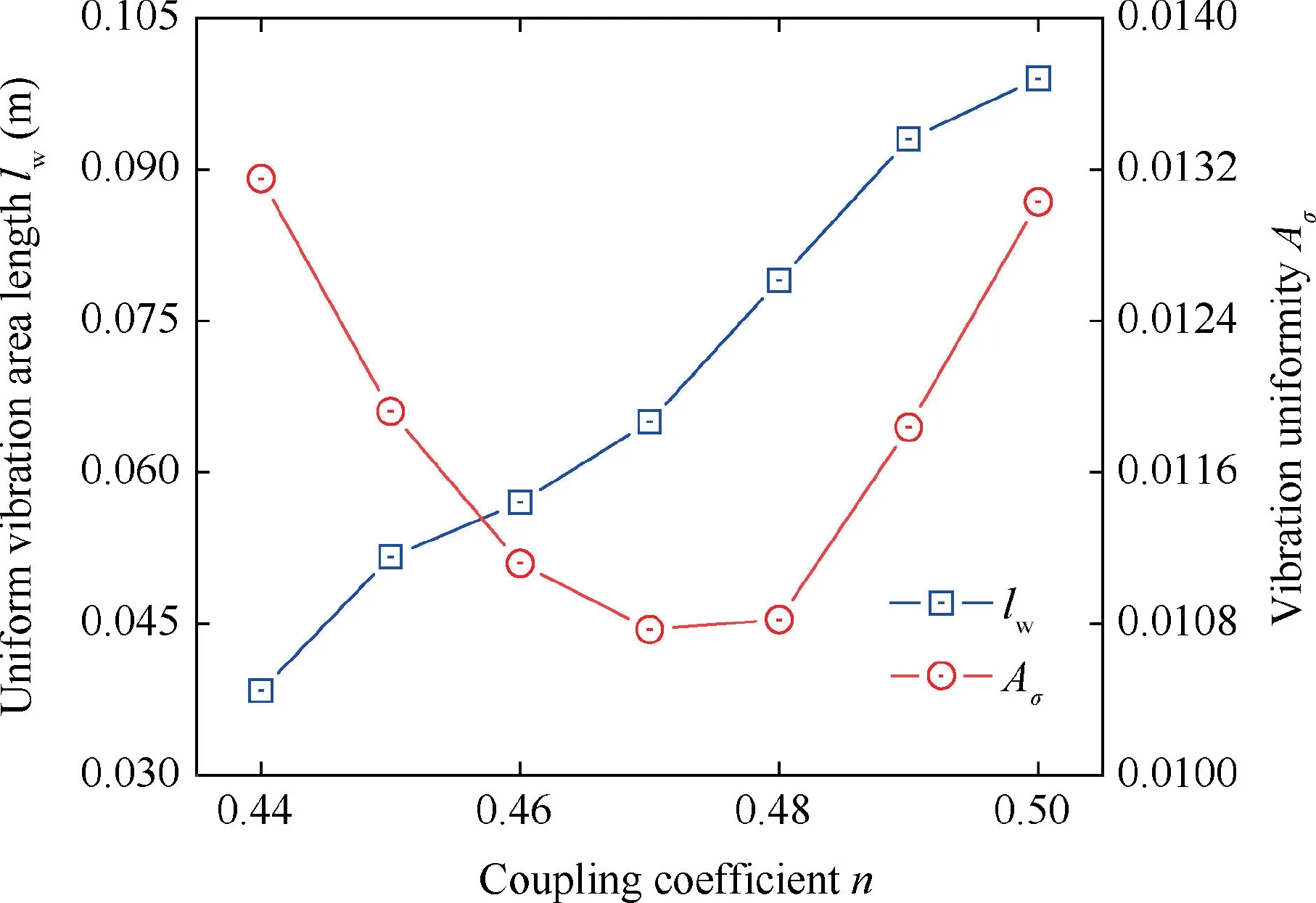
Fig.5 Effect of coupling coefficient on uniform vibration area.
3.3.Influence of the coupling coefficient on resonant frequency
A correction factor α is applied to correct the error between the theoretical and the actual resonant frequency.The actual and theoretical resonant frequencies,are calculated through the FEM and apparent elastic method,respectively.Fig.6 shows the relationship among the correction factor,coupling coefficient and actual resonant frequency.The correction factor decreases linearly from 1.083 to 1.006 with an increase of coupling coefficient from -4.075 to -1.488 as displayed in Fig.6(a),which can be fitted as:

When the coupling coefficient further increases from-1.488 to-0.326,the correction factor changes slightly(from 1.006 to 1.003),indicating that the correction factor is approximately equal to 1 when the coupling coefficient is between-1.5 and -0.33.
As illustrated in Fig.6(b),the correction factor increases rapidly from 0.996 to 1.149 with the increase of the coupling coefficient from 0.329 to 0.398.When the coupling coefficient increases further to 0.772,the correction factor increases slowly to 1.199.Afterwards,the correction is close to 1.20 when the coupling coefficient exceeds 0.772.As a result,a fitted curve is established to represent the relationship between α and:

Consequently,the correction factor betweenandis obtained as follows:

According to Section 3.1,when the coupling coefficient is close to 0,the width of plate device is less than 1/4 wavelength.Therefore,when -0.33 ≤<0.33,the plate device satisfies 1D ultrasonic vibration theory.Additionally,the results in Fig.6 reveal that the influence of the resonant frequency on the correction factor is very small.
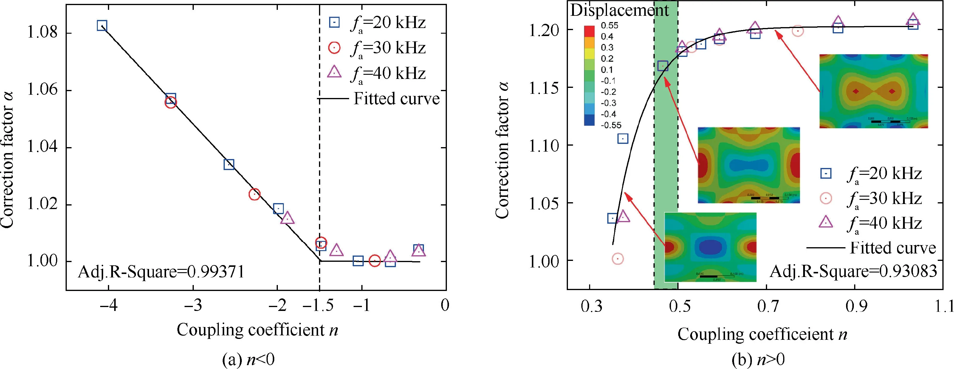
Fig.6 Relationship between correction factor and coupling coefficient.
4.Structural redesign and vibration tests of ultrasonic vibration plate device
4.1.Structural redesign
On the basis of Section 3,the optimal coupling coefficient and frequency factor are attained.Hence,the relationship among the geometric parameters (length and width),resonant frequency and L2T1 vibration mode can be described in Eqs.(2),(3)and(6).Namely,the length and width can be calculated through Eqs.(2),(3) and (6) in the plate device design,when the target resonant frequent is a constant.However,there are some other factors which should be considered in the design.They are the effects of grinding wheel and workpiece on the ultrasonic vibration.
It is noted that the vibration energy is originally limited in the plate when the cutting processing doesn’t occur.When the cutting processing occurs,some vibration energy transmits to the abrasive grains through the interface of workpiece and abrasive grain.Hence,the large cutting force causes the large deformation and further causes the large interface,which may lead to the increase of energy transmission and resonance loss.However,the interface of workpiece and abrasive grain is very small in UVAG,indicating that the energy loss rate is small,and the plate device can keep resonance in the current situation.
A cuboid workpiece with length,widthand heightis fixed in the center of the plate device surface.The material of workpiece is Inconel 718.The relationship between the size of workpiece and the resonant frequency is obtained through the modal analysis of FEM.The detail of simulation is listed in Table 2.It has been found that the resonant frequency decreases with the increase of workpiece length and width,as displayed in Fig.7.When the workpiece length and width are 60 mm and 30 mm,respectively,the resonant frequency is 143 Hz(0.7%)less than that without the workpiece,indicating that the value of resonant frequency reduction has a linear relationship with the mass of workpiece and the workpiece of small size has slight effects on the plate device resonance.
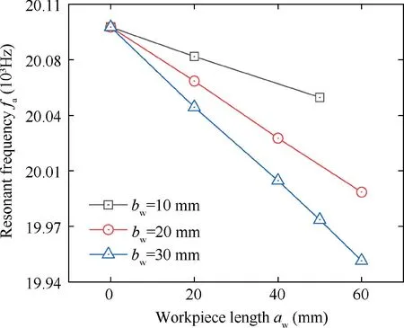
Fig.7 Effects of workpiece length and width on resonant frequency.
In order to fix the workpiece,the array holes with diameter of 5 mm need to be fabricated in the central area of the plate device.The total hole quantity is,as listed in Table 2.With an increase of total hole quantity from 0 to 49,firstlyincreases from 20.096 kHz to 20.127 kHz,then decreases to 19.984 kHz,as shown in Fig.8(a).Moreover,the vibration uniformity becomes better after the holes are fabricated.Whenis 16,the minimumis obtained,indicating that an excellent vibration mode is achieved,as displayed in Fig.8(b).Consequently,when the total hole quantity is within a certain range,the holes can slightly affect the resonant frequency and obviously improve the vibration mode.
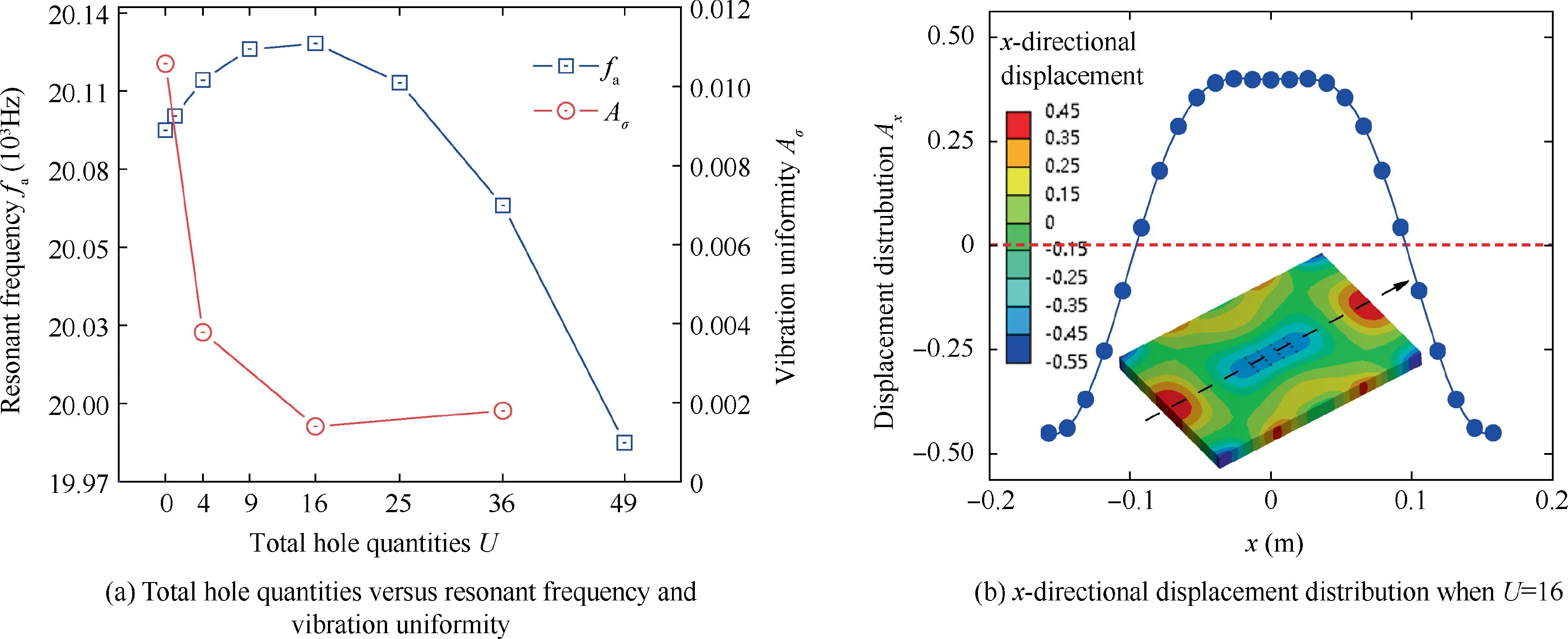
Fig.8 Effects of hole quantities U on L2T1 vibration mode.
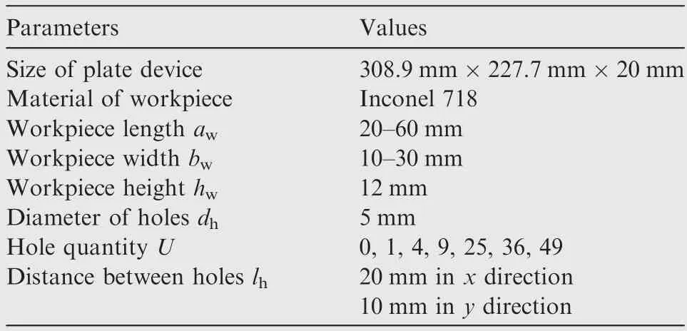
Table 2 Parameters of FEM simulation in detail.
4.2.Vibration tests
Fig.9 shows the FEM analysis results of modal,harmonic response and transient structure simulated by Ansys Workbench software.The bottom of legs was set to be fixed in the simulation.In the harmonic response analysis,the range of sweep frequency was from 19.300 kHz to 21.050 kHz.In the transient structural analysis,the drive displacement was along the-axis and was applied in the surface of the piezoelectric ceramics(Fig.9(a)).The value of drive displacement with time was like a sine curve.The time step and step end time were set to be 10s and 3×10s,respectively.
The resonant frequency calculated through the modal analysis is 20.017 kHz(Fig.9(a)),which is very close to the value of the modified apparent elastic method (20.000 kHz).The frequency error is less than 0.85%.Meanwhile,the value of resonant frequency calculated through the conventional apparent elastic method is 17.208 kHz with the frequency error of 14.03%,indicating that the modified apparent elasticity method is more accurate.The results of harmonic response analysis (Fig.9(c)) suggest the resonant frequency is 19.946 kHz which is consistent with the results of modal analysis and the modified apparent elastic method.Fig.9(d) illustrates the displacement of workpiece and the piezoelectric ceramic with time calculated through the transient structural analysis of FEM.These results of transient structure analysis suggest that the workpiece displacement in thedirection(5×10m)is much larger than that in theanddirections(less than 5×10m and 4×10m,respectively),indicating that the resonance of the ultrasonic vibration plate device is achieved and the single-directional workpiece ultrasonic vibration is obtained.
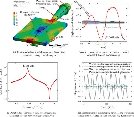
Fig.9 Vibration analysis calculated through FEM.
The impedance analysis was performed using the Model PV520A Impedance Analyzer,and the amplitude of ultrasonic vibration was tested by the EU05 eddy current transfer sensor from Micro-Epsilon,as shown in Fig.10.The eddy current transfer sensor was connected to the Eddy 3300 Multifunction Controller and an oscilloscope,which presented the voltage waveform and value of resonant frequency.Based on the results,the resonant frequency of the system without workpiece is 19.82 kHz.The frequency error is probably caused by the material property error and assembling.The dynamic resistance is 38.24 Ω,suggesting that the impedance matching is sustainable. When the workpiece (Size:30 m×10 m×10 mm) is fixed on the plate device,the resonant frequency decreases to 19.73 kHz.In the case of 90%output power of the ultrasonic generator,the amplitude of 9 μm has been detected on the workpiece surface in thedirection.Moreover,the amplitudes alonganddirections are both less than the minimum resolution of the eddy current transfer sensor (1 μm).The results are in consistent with the results of FEM.
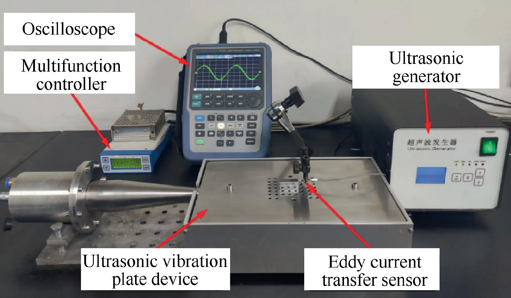
Fig.10 Vibration tests setup.
Fig.11 shows the vibration amplitude distributions on the edges of ultrasonic vibration plate device acquired through measurements and simulations.It can be found that the distributions of nodes and peaks of measurements and simulations are consistent,indicating that the actual vibration modes of plate device are similar as the simulated results of Fig.2.
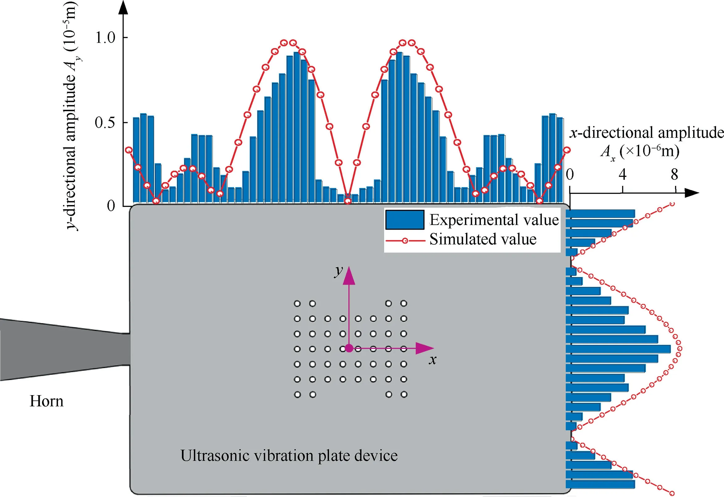
Fig.11 Vibration amplitude distribution on edges of plate device acquired through measurements and simulations.
5.Machining behavior of ultrasonic vibration-assisted creep-feed grinding of Inconel 718
5.1.Experimental conditions and parameters
The experimental conditions and parameters are shown in Fig.12 and listed in Table 3.The workpiece ultrasonic vibration system was fixed on the Blohm Profimat MT-408 surface grinder.The ultrasonic generator with maximum output power of 500 W was utilized to produce electric energy to the ultrasonic transducer,which was fixed in a protective case to prevent the coolant.Air coolant was continuously injected into the protective case to maintain ultrasonic transducer operating steadily.The workpiece was ground by the alumina grinding wheel.The code of this grinding wheel was 13A80FF22V35M.The abrasive grain was 80# mesh with a grain diameter in the range of 160-200 μm.Moreover,the grinding wheel was trimmed by a single point diamond dresser to keep high cutting ability.The parameters are as follows:dressing speedof 20 m/s,dressing feed speedof 150 mm/min,and depth of dressing cutof 0.2 mm.
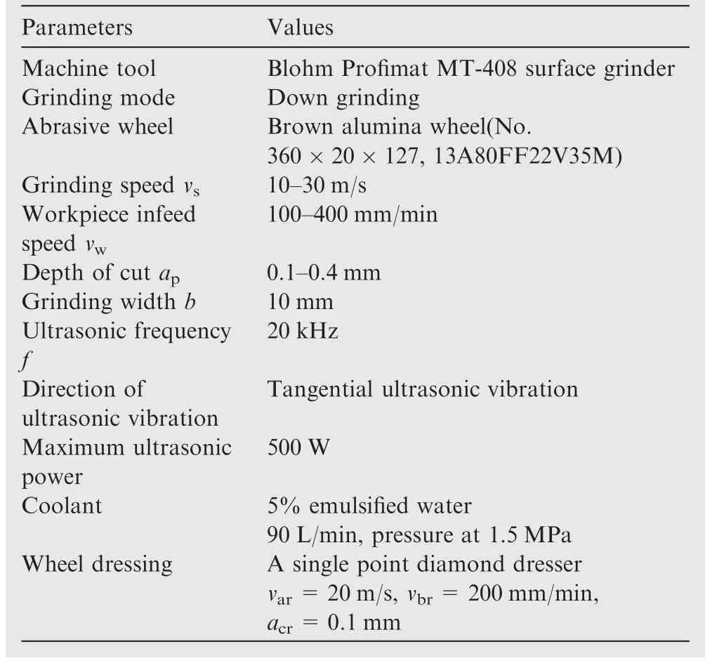
Table 3 Grinding experimental parameters.
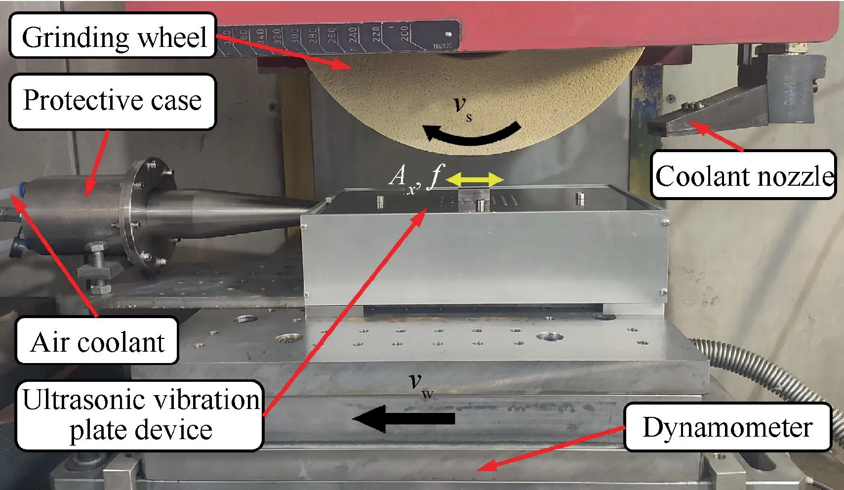
Fig.12 Grinding experimental conditions.
The grinding force was detected by Kistler 9253B dynamometer.The MAHR M2 perthometer was utilized to measure the workpiece surface roughness.5 points along the grinding direction were measured on every workpiece surface.The sampling length and assessment length of measuring were 0.8 mm and 5.6 mm,respectively.The surface morphology of workpiece was observed by the Sensofar confocal microscopy and Quanta 200 scanning electron microscope.In this investigation,the average values of force signals were used to represent the grinding force in UVAG.In order to acquire reliable data,each value of grinding force under same processing parameters was measured three times.The final value was accordingly obtained by averaging these results.In particular,all the grinding forces mentioned later were the average ones.
5.2.Grinding force
To evaluate the effect of ultrasonic vibration on grinding force,the force reduction rate is introduced,which can be expressed as follows:

whereandare the grinding forces in CG and UVAG,respectively.As shown in Fig.13(a),when the depth of cut is 0.1 mm,the normal and tangential force of conventional grinding (CG) are 232 N and 78 N,respectively.When amplitude of workpiece ultrasonic vibration is 9 μm (UVAG),the normal and tangential force decrease by 14.2% and 9.0%,respectively.Furthermore,with an increase of the depth of cut to 0.4 mm,the normal force of UVAG is 5.9%lower than that of CG,the difference between the tangential forces of CG and UVAG is small,indicating that the influence of ultrasonic vibration on grinding force becomes weak with the increase of depth of cut.Fig.13(b) illustrates the relationship between grinding force and workpiece infeed speed under the condition of=15 m/s and=0.1 mm.When the workpiece infeed speed is 100 mm/min,the normal and tangential force of CG are 333 N and 155 N,respectively.With an increase of workpiece infeed speed to 400 mm/min,the normal and tangential forces of CG increase to 484 N and 237 N,respectively.It has been found that the difference between the normal forces of CG and UVAG is decreased from 58 N to 20 N and the difference between the tangential forces of CG and UVAG mainly remain unchanged when the workpiece infeed speed increases.In Fig.13(a),it is found that the force reduction rate is decreased with the increase of depth of cut when the cutting speed and workpiece infeed speed are constant.In Fig.13(b),the force reduction rate is decreased with the increase of workpiece infeed speed when the depth of cut and grinding speed are constant.This phenomenon indicates that the effect of ultrasonic vibration on grinding force is reduced when the workpiece infeed speed or the depth of cut increases.Furthermore,the grinding parameters of smalland largeis supe-rior to that of largeand smallin UVAG when the material removal rate per width (=) is constant.
Fig.13(c) shows the influence of grinding speed on force when the depth of cut and workpiece infeed speed are 0.1 mm and 100 mm/min,respectively.The normal and tangential forces of CG decrease with an increase of grinding speed.The maximum 15% and 11% difference of normal and tangential forces between CG and UVAG are achieved with the increase of grinding speed from 10 m/s to 30 m/s.However,the difference of grinding force between CG and UVAG changes little with the increase of grinding speed,suggesting that the grinding speed is not sensitive to the influence of ultrasonic vibration on the grinding force.
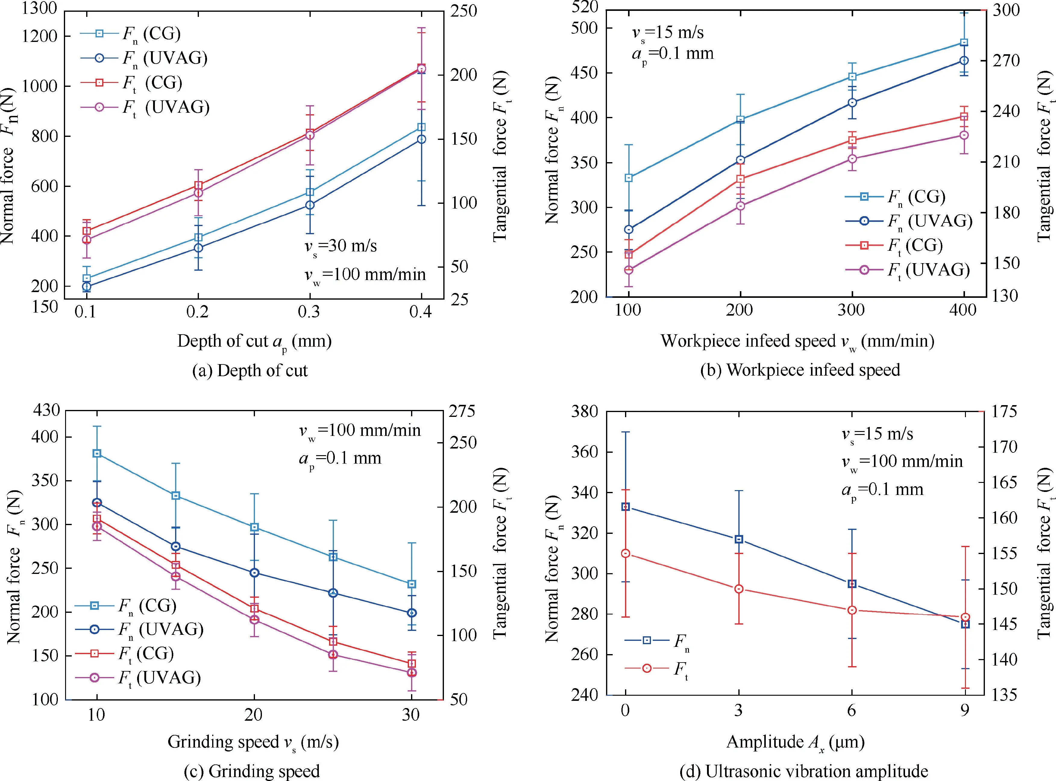
Fig.13 Effects of grinding parameters on grinding force in UVAG.
Fig.13(d)shows the relationship between the grinding force and the amplitude Aof workpiece ultrasonic vibration.The normal grinding forces decrease steadily as the amplitude increases from 0 to 9 μm.However,the decreasing value of tangential force is reduced gradually with the increase of amplitude.According to Poisson effect,the additional ultrasonic vibration of small amplitude in thedirection is generated on the workpiece surface with thedirectional ultrasonic vibration.The amplitude ofdirectional vibration is proportional to that ofdirectional vibration.Therefore,the increase of amplitude ofdirectional vibration decreases the effects of tangential ultrasonic vibration-assistance and causes the reduction of decreasing value of tangential force.
It can be found that the normal and tangential force reduction rates are 21% and 5.8% under the condition of=15 m/s,=400 mm/min and=0.1 mm (Fig.13(b)).However,the normal and tangential force reduction rates are reduced to 5.9% and approximate 0 when the processing parameters are=30/s,=100 mm/min and=0.4 mm(Fig.13(a)).Refs.[10,15,45-47] studied the grinding force of difficult-to-cut alloys in UVAG.These results indicated that the normal force reduction rate was mainly in the range of 5-30%,and the tangential force reduction rate was in the range of 0 (very small value)-40%.Furthermore,the results of Refs.[10,47] suggested that the tangential force reduction rate was commonly much less than the normal force reduction rate,suggesting that the effect of ultrasonic vibration on the tangential force was worse than that on the normal force.Nevertheless,the results of Refs.[15,45]suggested that the tangential force reduction rate was larger than the normal force reduction rate.This phenomenon indicated that the effect of ultrasonic vibration on the tangential force was superior to that on the normal force.But in their results,the small tangential force reduction rate was also measured under some processing parameters.According to the abovementioned results,an appropriate processing parameter is helpful to enhance the effect of ultrasonic vibration-assistance to the grinding force.When the processing parameters are improper,the reduction of grinding force in UVAG is poor.Compared to the normal grinding force,the tangential grinding force is probably more easily affected by the processing parameters.The tangential force reduction rate in UVAG may be very small or noticeable due to the different processing parameters.
One reason for force reduction is the effects of the acoustic softeningand ultrasonic friction reduction.In workpiece ultrasonic vibrating,the flow stress of material is reduced by the superimposition of the stress caused by ultrasonic vibration and the internal stress,reducing the yield stress of material.Hence,this phenomenon eases the plastic deformation of chips.According to Refs.[48,54],the flow stress decreases with the increase of ultrasonic vibration amplitude,suggesting that value of force reduction increases with the increase of amplitude.Additionally,based on the shear friction model,the friction stress can be written as:


5.3.Machined surface roughness and morphology
As shown in Fig.14,the machined surface roughnessis reduced 10% (from 0.43 μm to 0.39 μm) with the increases of ultrasonic vibration amplitude from 0 to 9 μm,suggesting that the machined surface quality is improved by the ultrasonic vibration.However,it is noted that the minimum surface roughness is reached when the amplitude is 6 μm,which is probably because thedirectional amplitude increases with the increase ofdirectional amplitude,leading to the small vertical ultrasonic vibration.Under such condition,the workpiece surface roughness would increase slightly.
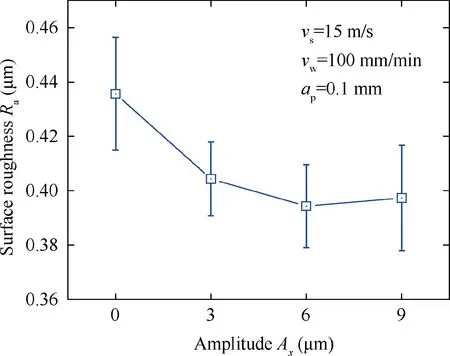
Fig.14 Effect of ultrasonic vibration amplitude on workpiece surface roughness of Inconel 718.
Fig.15 displays the acquired surface morphology and cross-section profiles of the workpiece along thedirection when the amplitude of ultrasonic vibration changes from 0 to 9 μm.The data of cross-section profiles were further analyzed through the Fast Fourier Transform (FFT) which is an efficient method for the analysis of workpiece surface.The typical spatial frequency is calculated to be 0.022 μmin CG (A=0,Fig.15(a)) and 0.030 μmin UVAG(Fig.15(b)-(d)),indicating that the width of grinding trace decreases after the ultrasonic vibration is generated.Moreover,the amplitude of typical spatial frequency in UVAG is smaller than that in CG.When the amplitude of ultrasonic vibration is 6 μm,the minimum amplitude of typical spatial frequency is obtained (0.22 μm).This phenomenon suggests that the depth of grinding trace in UVAG is smaller than that in CG.Consequently,the ultrasonic vibration-assistance in grinding leads to the decrease of depth and width of grinding trace (Fig.15(e)),which can decrease the workpiece surface roughness.As a consequence,the optimal value of ultrasonic vibration amplitude is 6 μm under the current experimental conditions due to the minimum surface roughness of workpiece as shown in Figs.14 and 15.
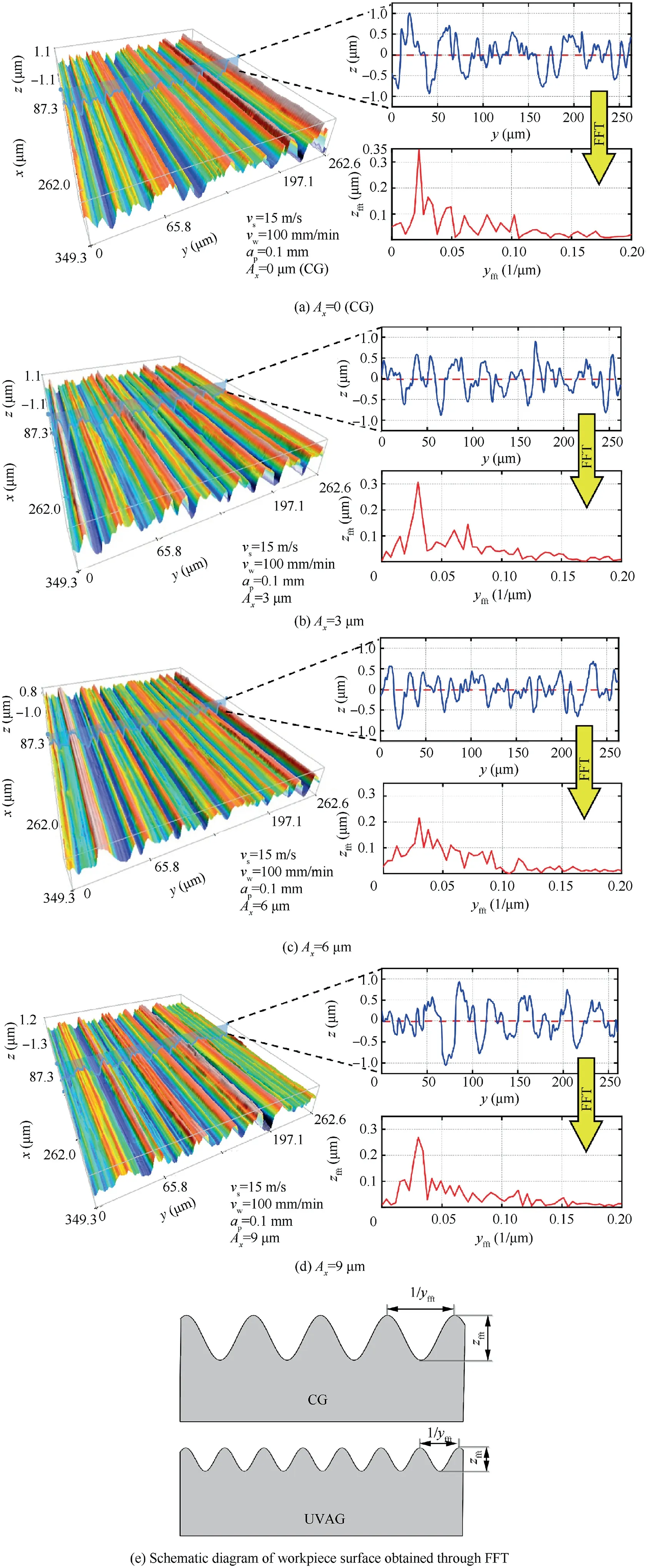
Fig.15 Machined surface morphology under different amplitude Ax in UVAG.
Fig.16 shows the representative topographies of the machined workpiece surfaces detected by SEM.Some pullouts(in the position A) and redeposited workpiece materials (in the position B) are found in CG (A=0),as displayed in Fig.16(a).The element contents in the positions A and B are further captured through the energy spectrum as shown in Fig.16(e)and(f).Fig.16(b)-(d)illustrate the surface topographies of UVAG.When the amplitude of ultrasonic vibration is 6 μm,the ploughingis observed,as illustrated in Fig.16(c).When the amplitude of ultrasonic vibration increases to 9 μm,the quality of workpiece surface deteriorates as the machined surface consists of some deep striations,which are probably caused by the-directional ultrasonic vibration(Fig.16(d)).
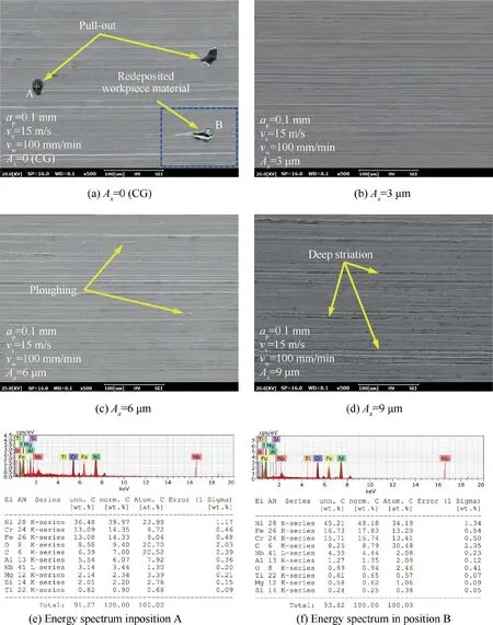
Fig.16 Micrographs of representative machined surfaces obtained under different amplitude Ax in UVAG.
6.Conclusions
The influence of vibration coupling effects on the L2T1 vibration mode were discussed through the theoretical analysis of apparent elastic method and simulation of FEM.Meanwhile,the machining behavior of the ultrasonic vibration plate device enabling the L2T1 vibration mode was tested experimentally.The main conclusions were as follows:
1.According to the positive or negative values of coupling coefficient,two basic vibration modes can be generated under L2T1 vibration mode.When the coupling coefficient is positive,the vibration phase of the adjacent edges is opposite under basic vibration mode.When the coupling coefficient is negative,the vibration phase of the adjacent edges is identical.
2.A suitable coupling coefficient is helpful to improve the machining behavior of ultrasonic vibration plate device.When the coupling coefficient is between 0.45 and 0.5,a uniform vibration area can be generated in the central area of plate device surface.The optimal value of coupling coefficient is 0.47,enabling the uniform vibration area length of 0.065 m and the minimal standard deviation of displacement.Furthermore,the apparent elastic method is improved by the correcting factor as the frequency error is less than 0.85% under the L2T1 vibration mode.
3.Compared with CG,the UVAG has advantages of 15%lower normal grinding force,11%lower tangential grinding force,10% lower workpiece surface roughness and fewer defects on the machined surface of Inconel 718 nickelbased superalloy.The optimal value of ultrasonic vibration amplitude is 6 μm under the current experimental conditions,enabling the minimum surface roughness.
The authors declare that they have no known competing financial interests or personal relationships that could have appeared to influence the work reported in this paper.
This work was financially supported by the National Natural Science Foundation of China (Nos.51921003 and 51775275),National Key Laboratory of Science and Technology on Helicopter Transmission (Nanjing University of Aeronautics and Astronautics) (No.HTL-A-20G01),Postgraduate Research&Practice Innovation Program of Jiangsu Province (No.KYCX20_0179).
