Effect of system response on partial surge initiated instability in a transonic axial flow compressor
Tinyu PAN ,Zhoqi YAN, ,Dkun SUN ,Simin LI ,Mengzong ZHENG,* ,Qiushi LI,,c
a Reserach Institute of Aero-Engine,Beihang University,Beijing 100083,China
b School of Energy and Power Engineering,Beihang University,Beijing 100083,China
c Key Laboratory of Fluid and Power Machinery,Ministry of Education,Xihua University,Chengdu 610039,China
KEYWORDS Partial surge;Plenum amplification;Rotating stall;System response;Stall inception;Transonic compressor
Abstract Partial surge is a type of instability inception in transonic compressors and occurs in the form of axisymmetric low-frequency disturbances localized in the hub region.Previous studies illustrate that the frequency of partial surge is set by the Helmholtz frequency of the entire system,which motivates to propose a hypothesis that the system response performs an important role in the formation of partial surge.For further verification,a series of experiments are conducted to explore the link between the propagating of the partial surge and the system feedback in this study.In the first case,an additional test point is set on the wall of the plenum to detect the system response.Combining the flow behaviors inside the plenum with the disturbances in the rotor tip and stator hub/tip regions,the effects of the system feedback on the occurrence of the continuous disturbances and the rotating stall cells are illustrated.In the second case,a screen is mounted at the compressor outlet to prevent positive feedback from the plenum.The experimental results demonstrate that in the absence of system feedback,it is the occurrence of spike-type stall inception that leads to the flow instability instead of that of partial surge.In addition,three flow phenomena in the second case are discussed,including the occurrence of the single pulse,the unstable process during the stall evolution and the switch of instability inception.
1.Introduction
The design and operation of compressors are constrained by the flow instability in the past decades.Rotating stall and surge are two generally accepted manners to produce flow instability in a compressor.Surge occurs as a large-amplitude oscillation of the overall mass flow,which results in serve mechanical vibration.Rotating stall performs as an asymmetric phenomenon with one or several stall cells and the overall mass flow rate remains nearly constant,but the compressor performance deteriorates significantly.To further understand the occurrence mechanisms of the stall and surge,which may contribute to operating margin enhancement,the onset and inceptions have been focused on.
There are two first found and generally accepted routes to rotating stall,which are referred to as long length-scale(‘‘modal” inception) and short length-scale (‘‘spike” inception).Modal wave is a gradual and progressive type of stall inception,which propagates at approximately 20%-45% of the rotor speed and is induced by the circumferential asymmetry.Spike develops rapidly with relatively large amplitude in several revolutions,which rotates at 70%-80% of the rotor speed and links to the tip vortices.However,due to the approaches in compressor design,some other stall inceptions were reported in recent years,which were quite different from the typical processes of both modal wave and spike.Mailach and Lehmannfound rotating instabilities in an axial compressor,which originated from the fluctuating blade tip vortex.Dodds and Vahdatiobserved stall cells rotating at a low speed in the hub region.Dell’Era et al.found prestall disturbances in the hub region and the instability evolution varied with the rotating speed.With a hybrid slotgroove casing treatment,Liu et al.and Li et al.investigated instability fluctuation with a low-frequency band in the hub region stall cells.At the same time,in our previous studies,a type of instability inception ‘‘partial surge” was observed in a transonic compressor under a high blade load in the hub region.
Partial surge appears in the form of hub region localized axisymmetric blockage,the evolution process starts from a single pulse to continuous disturbances,which finally leads to rotating stall.The frequency of partial surge disturbances is constant during the inception period and it is approximately equal to the Helmholtz frequency of the test facility.The above-mentioned results motivate to propose a hypothesis that the system response presents a key role in the formation of partial surge-type stall inception.To verify this hypothesis,based on an additional high-response dynamic test point in the plenum,the effect of the system feedback on the propagation of partial surge is investigated.Furthermore,to study whether the system feedback is necessary for the formation of partial surge,a screen is mounted at the interface between the compressor outlet and the plenum to isolate the compressor from the Helmholtz oscillation of the plenum.
The following part of this paper is organized as follows:the experimental facility is briefly introduced in Section 2,which includes the test rig,measurement methods,and the experimental configurations.In Section 3,the experimental results are presented and analyzed to demonstrate the flow instability evolutions of the two test cases,which is then followed by a discussion in Section 4.Finally,the main findings are concluded in Section 5.
2.Experimental setups
2.1.Research subject
The test equipment is a single-stage transonic compressor in an aero-engine.The design parameters of the compressor are given in Table 1.Detailed parameters of the rotor and stator blades,including the absolute flow angles and solidity,are listed in Table 2.Since the diffusion factor in the rotor hub region is estimated to be near 0.5 at the design point,the tandem stator design is used to decrease the hub loading of the stator.The tested compressor is driven by a power turbine,and the rotation speed can increase continuously to the maximum value of 24000 r/min.A schematic of the test equipment is presented in Fig.1.The function of the settling chamber is to provide a uniform inlet flow condition for compressors,and the total pressure inside the chamber equals to the local atmospheric pressure.The position of the throttling devices is installed downstream of the plenum,marked as No.6.The throttles are fully opened at the initial work condition,which includes three butterfly valve control systems.According to the research experiences on this test equipment,the adjustment of the throttling devices varies slightly faster when the compressor is far away from the stall margin.The movement of the throttling devices is halted when collecting the performance points.However,the throttling devices are adjusted extremely slowly near the last stable point.After collecting the last stable point,the compressor stalls under a small variation of gas flows controlled by the throttling devices.
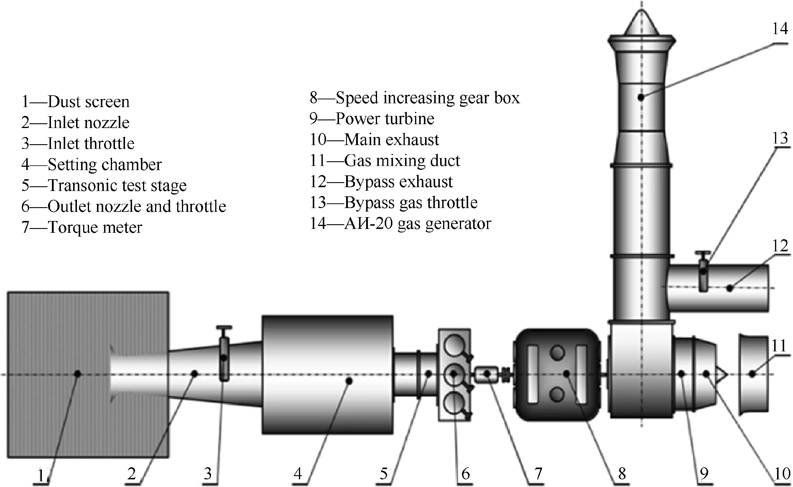
Fig.1 Schematic diagram of rig test facility.
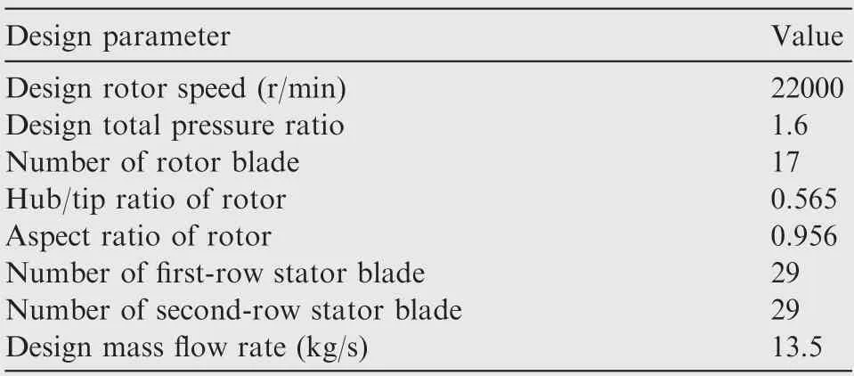
Table 1 Design parameters of transonic compressor.

Table 2 Detailed blade parameters of test compressor.
2.2.Measurement layout
Fig.2 shows the arrangements for measuring positions.To measure the total pressure at both the inlet and outlet of the compressor,low-response probes are placed at the Crosssections A and D,which including five and six measuring positions along the radial direction.The specific radial measuring positions of the probes at the Plane A and the Plane D are 8.23%,24.71%,43.52%,65.88%,90.59,and 6.33%,18.99%,32.91%,49.37%,65.82%,84.81%span,respectively.The design principle follows that the circumferential area between adjacent measurement positions is the same.Thus,the total pressure in the section is obtained by the areaaveraged method.The rotating speed,ambient pressure,and temperature are also measured.All of these steady data are acquired and calculated to identify the operating conditions and the performance map of the compressor.
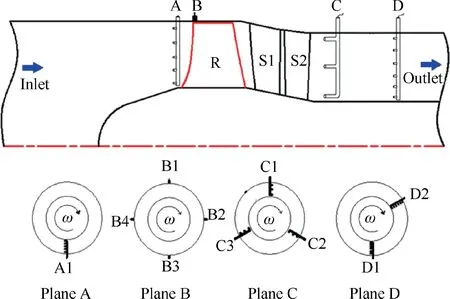
Fig.2 Schematic of compressor cross-section showing layout of transducers.
To capture the instability evolution,four high-response static pressure transducers (B1 to B4) are placed at 0°,90°,180°,and 270°at the inlet surface in the vicinity of the leading edge of the rotor tip.At the same time,C1 to C3 are circumferentially uniform on the Cross-section C of an axial chord length of the tandem stators,and the high-response transducers are installed in the inner part of each total pressure comb,which is presented in Fig.3.The transducers at the Plane C are situ-ated at 10%,50%and 90%radial locations.The circumferential positions of B1 and C1 are the same.
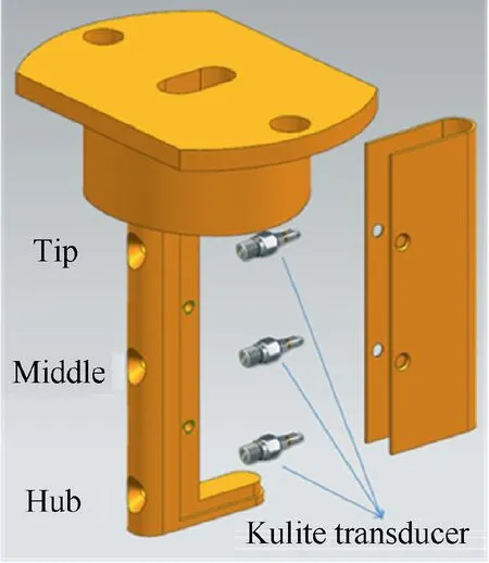
Fig.3 Schematic diagram of high-response dynamic total pressure comb structure.
2.3.Test plane
The present study focuses on the 88% of the design rotor speed,i.e.,19360 r/min,at which the partial surge was first detected.Two cases of experiments are designed and conducted using the test facility and measurement layout introduced above.
In the first case,an additional test point is mounted on the inner wall of the plenum to detect the pressure oscillation inside the plenum during the partial surge-type instability evolution.The location is presented in Fig.4 in the view from the outside of the plenum.Furthermore,due to that the screen can accelerate the mixture of the partial surge disturbances in the spatial dimension and decrease the disturbance amplitude in the time dimension,it is capable of suppressing the system feedback inside the plenum.Therefore,in the second case,a screen with an appropriate porosity is mounted at the interface between the compressor outlet and the plenum,as presented in Fig.4 as well.The purpose is to verify the effect of the system response on the occurrence of the partial surge by revealing the instability evolution of the compressor without the influence of the plenum.
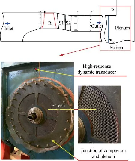
Fig.4 Schematics of test point in plenum and of screen.
The screen is designed based on the experiences from our previous experimental study,which presented the pressure loss ability of various screens with a different porosity.To characterize the screen,the total pressure loss coefficient ()is generally a parameter of screen geometry and spacing,and in this study,value of the screen is 0.715.
3.Results analysis
The experimental results of the test compressor are presented in this section.In the first part,the compressor instability evolution and the axial oscillation of the system are analyzed to reveal the effect of the system feedback during the stall evolution.The second part presents the instability behaviors and stall inception with the screen between the compressor and the plenum to indicate the significance of the system response for the formation of partial surge-type inception.
3.1.Flow behaviors inside plenum during stall inception
Windows Fourier Transform (WFT) is used to analyze the data recorded by the transducer B1 (in the rotor tip region),C1 hub (at the stator outlet hub),and P (in the plenum) to investigate the compressor instability evolution,as presented in Fig.5.The-axis represents the frequency,the-axis is the rotor revolutions,and the-axis represents the amplitude of the signal oscillations.
For the results obtained at both the rotor tip and stator outlet hub,the pink lines,the red lines and the blue lines represent the low-frequency disturbances of 12 Hz,the rotating stall cells of 178 Hz and the Rotor Rotation Frequency(RRF) of 323 Hz,respectively.It presents that the lowfrequency disturbances (12 Hz) occur first near the 200th revolution at C1 hub,and then triggers the development of rotating stall cells,which is consist of the partial surge-type stall inception previously reported.For the data in the plenum,Fig.5(c) shows that only the disturbances with a similar frequency as partial surge disturbances could be detected during the entire stall process.Based on the above results,an appropriate data filter method is applied:the frequencies above 500 Hz are removed,and then the signals are band-block filtered from 90% of RRF (290.7 Hz) to 110% of RRF(355.3 Hz) to remove the rotor rotation frequency.
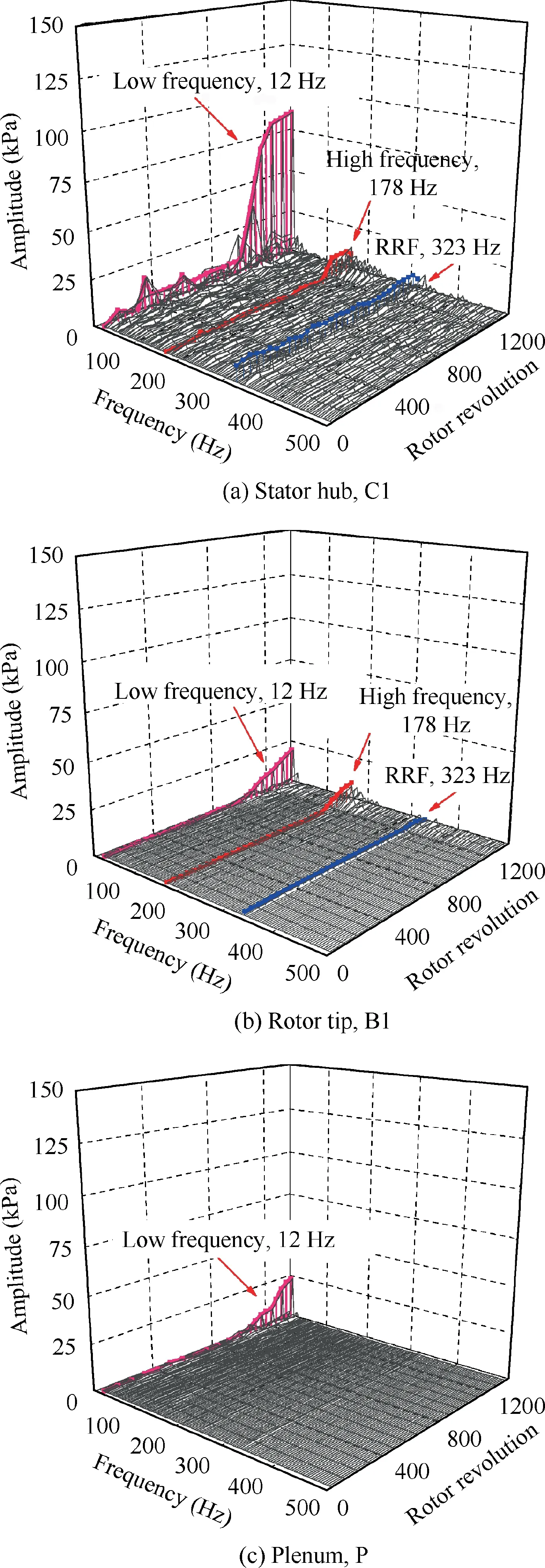
Fig.5 WFT analysis of data recorded at C1 hub,B1 and P(Case 1).
The recorded data are analyzed to obtain the variation of static pressure in the rotor tip region (B1) and the plenum(P),and the total pressure at the stator outlet (C1 hub and C1 tip)in the time domain,as presented in Fig.6.The horizontal axis represents the rotor revolutions,and the vertical axis represents the normalized pressure.Since the amplitudes of all data oscillations reach the peak after the compressor stall,each maximum value of data oscillations (around the 1300th revolution) at different locations is used to normalize the previous corresponding data.The disturbance amplitude at about 1300th revolution is defined as 0.9 for better observation.At the same time,to further study the features of the disturbances during the different states in the entire evolution,the pressure variations in three specific time durations are zoomed-in Fig.6.
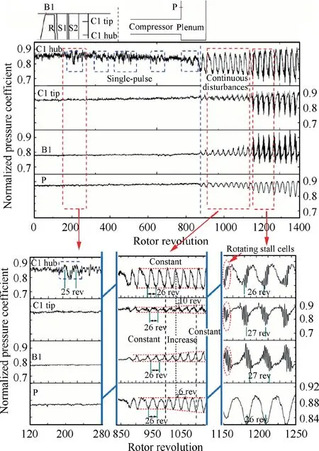
Fig.6 Compressor instability evolution in time domain(Case 1).
Due to that the previous studyrevealed that the partial surge disturbances originated from the hub region,the total pressure oscillation at the C1 hub is first analyzed.Several single pulses appear from 200 to 875 rotor revolutions,as presented by the blue dashed rectangles.Then,the single pulse converts to the continuous disturbances around the 875th revolution,and the rotating stall cells emerge at the 1150th revolution.
For the state of single pulses,there is no obvious disturbance in both the rotor/stator tip regions and the plenum.Thus,the single pulse disturbance is only detected in the hub region.For the state of continuous disturbances,the disturbances with a similar frequency,which corresponds to around 26 revolutions in one period,are detected in both the rotor/stator tip regions and the plenum.However,compared with the disturbances at C1 hub,there are a phase lag of 10 revolutions and a phase lag of 6 revolutions in C1 tip and in the plenum,respectively.The phases at B1 tip and in the plenum are the opposite.In terms of the amplitude,the value at C1 hub remains constant,as marked by the red dashed lines.However,the values increase gradually in both the rotor/stator tip regions and the plenum from the 1000th to the 1100th revolutions,while the values keep the same during the rest of the time in this state.For the state of rotating stall,the frequencies of the partial surge continuous disturbances remain constant at all locations.The amplitudes of the partial surge continuous disturbances are increased compared with the state when the rotating stall does not occur.The high-frequency disturbances corresponding to the rotating stall cells could be detected in almost all locations including the rotor/stator tip regions and the stator outlet hub region except in the plenum.
The aforementioned results describe the flow behaviors inside the plenum during the entire stall process.Then,the effect of the system response,which can be indicated by the static pressure oscillation inside the plenum in our case,will be investigated as follows.As a backup,the variation of total pressure at both the stator outlet hub/tip versus the overall mass flow rate of the compressor is presented in Fig.7.
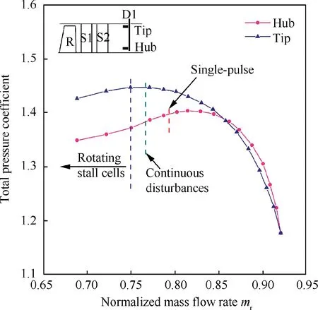
Fig.7 Total pressure coefficient at stator outlet hub/tip during evolution.
The total pressure coefficient is defined as the ratio between the value recorded by the low-response probe D1 and the local atmospheric pressure.The normalized mass flow rate is defined as the ratio between the actual mass flow rate and the design mass flow rate.The pink line and the blue line represent the variation of the total pressure in the hub region and the tip region.The dashed lines in red,green,and purple represent the triggering moment of single pulse,continuous disturbances and rotating stall cells,respectively.The results indicate that the total pressure at the stator outlet hub is decreasing before the occurrence of continuous disturbances,even before the show-up of single pulses,which indicates that the total pressure at the stator outlet hub is decreasing during the transient process from the single pulse to the continuous disturbances.At the same time,the total pressure at the stator outlet tip still increases after the occurrence of single pulses and reaches the peak when the rotating stall occurs.
To investigate the effect of the system response on the transition process from the single pulse to the continuous disturbances,the dynamic data both in the stator outlet hub(including three transducers uniformly placed in the circumferential direction) and the plenum are analyzed,as presented in Fig.8.The different moments during the transition process are labeled fromto.Due to that the inlet condition is uniform and constant,the phase variations of the static pressure and the velocity are opposite.Therefore,the values detected by the high-response dynamic static pressure transducers installed on the leading edge of the rotor tip can measure the variation of the system mass flow rate.The results of four transducers are averaged and are low-pass filtered to only keep the lowfrequency oscillation.
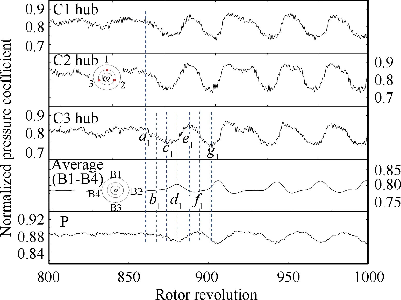
Fig.8 Effect of system response on transition from single pulse to continuous disturbances.
The disturbances at the stator outlet hub illustrate that the low-frequency perturbations are axisymmetric.Due to the occurrence of a localized blockage,the total pressure starts to drop at the moment.After 6 revolutions,the mass flow rate starts to decrease at the moment.At the same time,the static pressure inside the plenum drops,which means that the backpressure for the compressor also decreases.Based on the variation presented in Fig.7,the total pressure at the stator outlet hub will increase due to the decrease of the backpressure.As a result,the total pressure at the stator outlet hub starts to increase at the moment.Also,after 6 revolutions,the mass flow rate starts to increase at the moment,which leads to the rising of the backpressure.At the moment,the backpressure returns to the same level as that at the momentwhen the total pressure at the stator outlet hub starts to decrease.Due to this effect,the total pressure at the stator outlet hub reaches the peak at the moment.However,both the mass flow rate and backpressure do not immediately decrease,which leads to the continuous increasing of both the mass flow rate and backpressure.At the moment,the value of backpressure reaches its peak,which is the highest so far.With this large backpressure,at the moment,the total pressure at the stator outlet hub reaches to a lower value compared with that at the moment.Then,the mass flow rate starts to decrease,which leads to a decrease in backpressure.The flow evolution enters into the next period.The results indicate that the feedback of the system amplifies the local total pressure oscillation in the stator hub by the influence of both the mass flow and the backpressure.The amplitude of the single pulses is increased.And the continuity of the disturbances is activated by the following natural axial mode of the entire system.
To further explain the process of how the local blockage at the stator hub triggers the overall oscillation of mass flow,the time history of total pressure at both the stator tip/hub and static pressure inside the plenum from the 800th to the 1000th revolutions is presented in Fig.9.
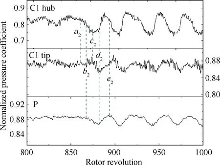
Fig.9 Detailed analysis of pressure oscillation onset inside plenum.
There are two moments selected,which are labeled asand.At the moment,the total pressure at the stator outlet hub starts to drop,which leads to the rising of total pressure at the stator outlet tip due to the rematch of the radial distribution of mass flow rate.The sudden increase of total pressure in the stator tip region could be considered as the local increase in mass flow.Based on Fig.7,both the local blockage at the stator hub and the local mass flow rising at the stator tip could result in the decrease of total pressure ratio,which could explain the decrease of the overall mass flow of the compressor at the moment.After the above evolution,the overall oscillation of mass flow is triggered,and the effect of system response further drives the switch from the single pulses to the continuous disturbances,as presented in Fig.8.
During the decrease of backpressure,the total pressure at the stator hub and that at the stator tip reach the trough and the peak at the moment,respectively.Then,the total pressure at the stator hub starts to increase while the total pressure at the stator tip starts to decrease.At the moment,even though the total pressure at the stator hub is still increasing,the total pressure at the stator tip stops decreasing and starts to increase due to the rising of the backpressure.At this moment,the phases of the disturbances at both the stator tip/hub are not the opposite anymore.Then,at the moment,the total pressure at the stator tip continues to increase due to the continuous decrease of that at the stator hub,even though the backpressure has already decreased.After this process,the phase difference between the variations of total pressure at the stator tip and hub remains to be 10 revolutions,which could be explained by the combined influence of both the rematch of radial mass flow distribution and the system response on the variation of total pressure at the stator tip.
To investigate the effect of the system response on the occurrence of the rotating stall cells,the variations of the static pressure in the plenum and the rotor tip region and the total pressure in the stator outlet hub region from the 800th to the 1200th revolutions are presented in Fig.10.For the data recorded by the four high-response dynamic transducers at the rotor tip,the high pass filtering is applied to detect the occurrence of the rotating stall cells.
When the total pressure at C1 hub reaches the trough near the 900th revolution,the averaged static pressure at the rotor tip is nearly at the peak value,which means the incidence at the rotor tip span increases to the maximum.As a result,the high-frequency disturbance starts to occur.When the total pressure at the C1 hub increases,the incidence at the rotor tip span starts to decrease,and high-frequency disturbances disappear.Due to this effect,the high-frequency disturbances appear and disappear periodically.At the 1000th revolution,the amplitude of the high-frequency disturbances increases,which leads to the increasing amplitude of both the mass flow rate and static pressure oscillation inside the plenum until the 1100th revolution.During this process,due to the high blade load at the stator outlet hub presented in Fig.7,the disturbance amplitude cannot further increase before the finally stall.Then,after a time period of 50 revolutions with the same oscillation level,at the 1150th revolution,the disturbance amplitudes at all locations are amplified due to the rapid development of the high-frequency disturbances at the rotor tip,which finally causes the flow instability.To explore the features of the high-frequency disturbances occurred in the tip region,the time duration from the 1125th to the 1200th revolutions recorded by B1 to B4 is zoomed-in.The data at B1 is repeated to facilitate the observation of circumferential propagation characteristics,and the disturbance propagation is marked by the red dashed lines.As depicted in Fig.10,it is found that the high-frequency disturbances are rotating stall cells with a rotating speed of 0.55 RRF.
From the 900th to the 1000th revolutions,there are several short time rotating stall cells which appear and disappear periodically.To study these short time rotating stall cells,the time period from the 875th to the 1050th revolutions are presented in Fig.11.Near the 900th revolution,the stall cell appears with the rotating speed corresponding to the frequency of 0.79 RRF,and disappears after only one circumferential propagation.After that,even though the oscillation amplitudes of both the mass flow rate and static pressure inside the plenum remain constant as presented in Fig.10,the rotating speed of the short time stall cells slow down due to the increase in spatial size,which indicates the increase of existing time durations.Therefore,the short time stall cells could be explained as the developing rotating stall cells which only occurs with lower incidence at the rotor tip.
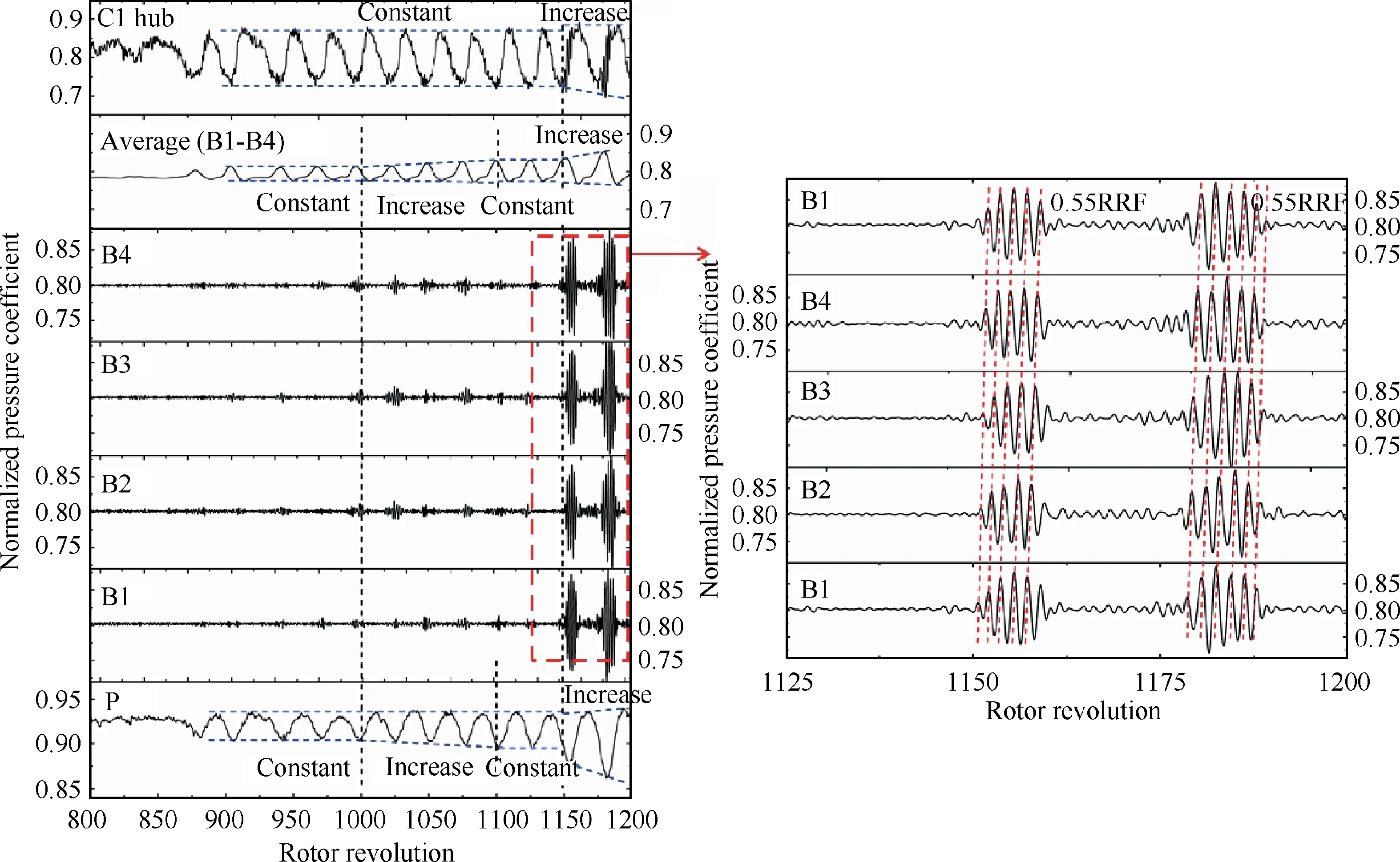
Fig.10 Effect of system response on occurrence of rotating stall cells.
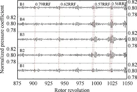
Fig.11 Development of short time rotating stall cells.
In summary,for the static pressure in the plenum,the continuous oscillations occur when the single pulse converts into the continuous disturbances in the stator hub region.And the amplitude of the static pressure oscillation in the plenum increases when the rotating stall occurs in the compressor.During this stall process,the main effect of the system response is to amplify the amplitude of the single pulse,and further convert it to be continuous disturbances.The system response has no direct effect on the occurrence of the rotating stall cells,but its oscillation amplitude is amplified by the rotating stall cells conversely.
3.2.Instability evolution of compressor without system response
To further study the effect of the system response,a screen is installed at the interface between the compressor outlet and the plenum to prevent the feedback effect inside the plenum.The performance evolution is compared with that without the screen,as presented in Fig.12.
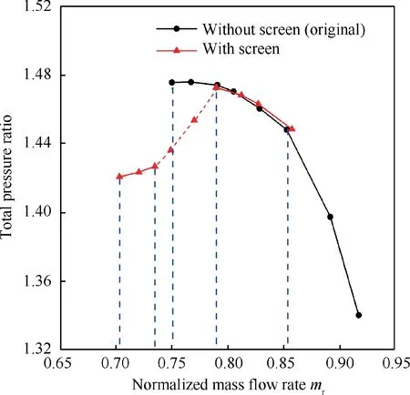
Fig.12 Comparison of characteristics with/without screen.
The mass flow rate of the chock point is 0.851,smaller than that without the screen,which corresponds to the high backpressure caused by the screen.When the mass flow rate is between 0.788 and 0.851,the measured curves are almost the same with/without the screen,which indicates that the screen does not change the overall performance of the compressor.When the mass flow rate is 0.788,a sudden drop in the total pressure ratio occurs and the compressor cannot maintain stable until the mass flow rate of 0.737.Then,the compressor can operate stably when the mass flow is between 0.737 and 0.705,and the flow instability occurs under the smaller mass flow rate.It probably implies that the instability evolution with the screen is not partial surge anymore.For verification,the dynamic data will be analyzed as follows.
The data recorded by the transducer B1 (rotor tip region),C1 hub(stator hub region)and P(in the plenum)are processed by WFT,as presented in Fig.13.For the data in the plenum,there is no obvious disturbance during the overall stall process comparing with that in Fig.5(c),which means that the system feedback is prevented by the screen.For the results obtained at the C1 hub,the low-frequency disturbance of 12 Hz starts to occur near the 1500th revolution and disappears rapidly,and the maximum amplitude is less than 40 kPa.However,for the partial surge instability evolution,as shown in Fig.5(a),the amplitude of the low-frequency disturbances at the stator outlet hub increases gradually until the final stall with about 90 kPa.For the data at B1 in Fig.13(c),there is no lowfrequency disturbance during the entire stall evolution,which is completely different from the partial-surge stall inception.In terms of the amplitude,the high-frequency disturbances without the system response is higher than that with the system response presented in Fig.5.The explanation is due to that the high-frequency disturbances appear and disappear periodically with the occurrence of the low-frequency disturbances,which prevents the amplitude development of the high frequency disturbances.At last,the rotating stall occurs near the 5000th revolution both in the stator outlet hub and rotor tip regions.The above results indicate that without the system response,the compressor instability inception is no longer partial surge.
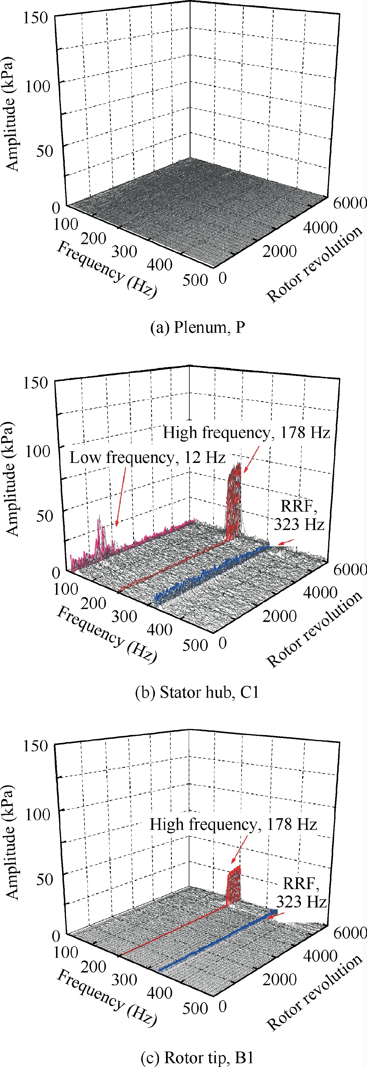
Fig.13 WFT analysis of data recorded at B1,C1 hub,and P(Case 2).
To investigate the instability inception without the system response,the time history data of the pressure (in the rotor tip region and the plenum) and total pressure (at the stator outlet)are presented in Fig.14.Since the amplitudes of all data oscillations reach the peak after the compressor stall,each maximum value of data oscillations (around the 5500th revolution) at different locations is used to normalize the previous corresponding data.
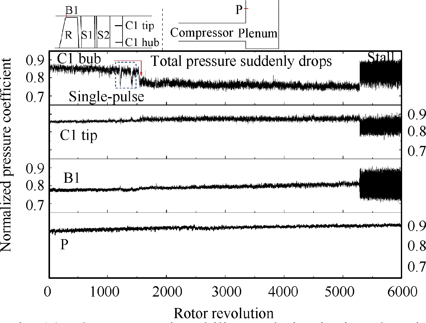
Fig.14 Compressor instability evolution in time domain (Case 2).
Due to that the system feedback is prevented,the amplitude of the disturbances in the plenum remains the same during the entire stall evolution.For the data at C1 hub,two single pulses occur at the 1200th and the 1400th revolution,as presented by the blue dashed rectangle,which corresponds to the lowfrequency disturbances near the 1500th revolution presented in Fig.13(b).At the 1500th revolution,a sudden dip of total pressure appears,and the single pulse cannot develop into the continuous disturbances.For the results both in the rotor/stator tip regions,there is no obvious disturbance before the 5300th revolution.After that,the high-frequency disturbances occur both in the stator hub/tip and rotor tip regions,which finally causes the instability.
To further determine the details of high-frequency disturbances causing instability,the data recorded by four highresponse dynamic transducers at the rotor tip from the 5260th to the 5310th revolutions are presented in Fig.15.The rotating stall occurs after the 5285th revolution,and the frequency of the disturbances is 178 Hz (0.55RRF),which are rotating cells,as marked by the red dashed lines.Before the final stall,the amplitude of the short-length scale disturbance rapidly increases in several revolutions,and the rotating frequency is 0.72RRF.Therefore,it is the spike inception that causes the flow instability.
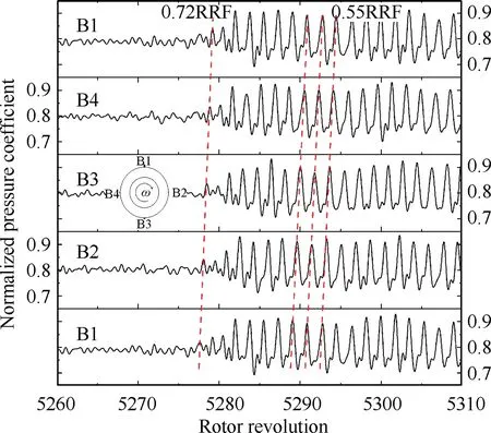
Fig.15 Propagation characteristics of stall inception at rotor tip.
In summary,the system feedback is prevented by the screen installed downstream of the compressor,and the instability inception correspondingly converts into spike-type.The results demonstrate that the effect of the system response that amplifies the single pulse into the continuous disturbances is one of the necessary conditions for the formation of the partial surgetype inception.
4.Discussion
This section is trying to discuss three flow phenomena existed in the case with the screen,which are the occurrence of single pulse without the system response,the unstable process of sudden drop of the total pressure ratio during the stall evolution,and the switch of instability inception between the cases with and without the system response.
(1) The occurrence of single pulse without the system response.Due to that the previous studyrevealed that the high blade load in the hub region is necessary for the occurrence of the initiated-disturbance of the partial surge,the effect of the screen on the spanwise distribution of total pressure ratio is investigated,as presented in Fig.16.A comparison of the total pressure ratio along the spanwise locations is conducted when the mass flow rate is 0.788.The results indicate that the characteristics of the high blade load in the hub region remain almost constant with or without the system response.Thus,the occurrence of the single pulse is not affected.
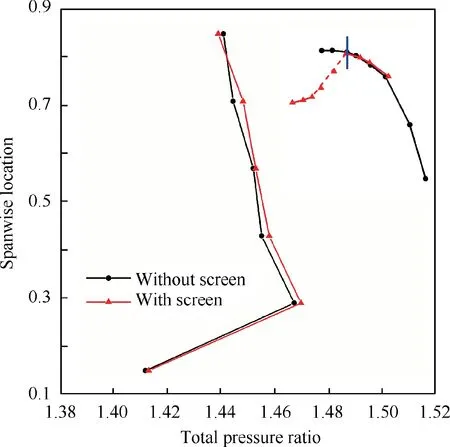
Fig.16 Effect of system response on occurrence of single pulse.
(2) The unstable process of sudden drop of the total pressure ratio during the stall evolution.To explain this flow phenomenon,the distributions of spanwise location of total pressure ratio at different mass flow rates are studied,as presented in Fig.17.As presented in Fig.12,two stable states of the mass flow rate are selected,labeled as(mass flow rate of 0.788) and(mass flow rate of 0.737).The red lines with square and star symbols represent the radial total pressure ratio with the screen atand,respectively.The stateoccurs before the sudden drop of the total pressure ratio,and the stateoccurs after that.The measured curves show that the total pressure ratio in the hub region decreases rapidly,while the value in the tip region can further increase.As a result,the rematching of blade loading leads to the occurrence of the unstable process,which further affects the compressor performance.
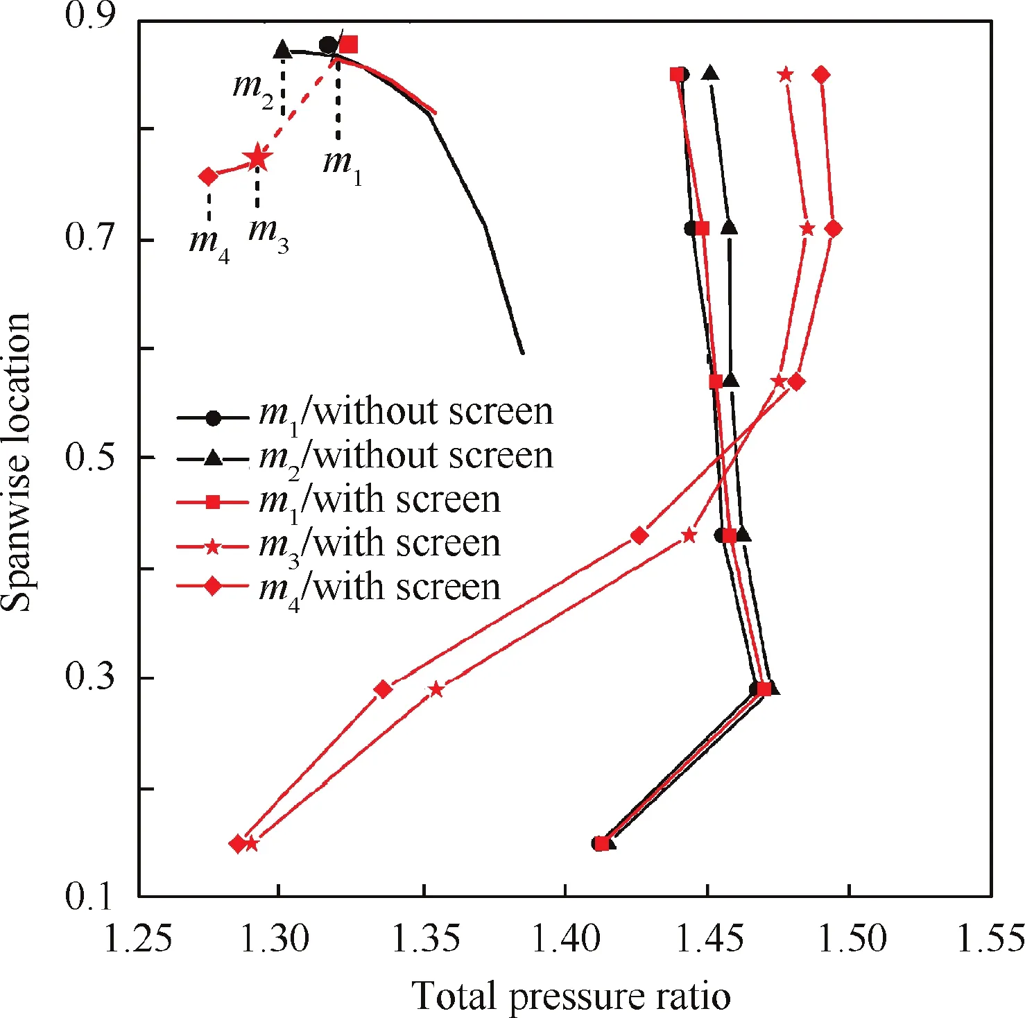
Fig.17 Total pressure ratio distribution along spanwise locations at different mass flow rate conditions.
(3) The switch of instability inception between the cases with and without the system response.The total pressure ratio distribution at the last stable point (labeled as)in the case without the system response is marked by the red line with diamond symbols in Fig.17.Compared with that atin the case with the system response,the hub loading decreases and the tip loading increases significantly,which causes the occurrence of spike-type inception instead of the partial surge.
5.Conclusions
In this paper,the effect of the system response on the partial surge-type inception is investigated experimentally in a transonic compressor.A new test point is set on the wall of the plenum to detect the system response during the stall evolution.To further explore the significance of the system response,a screen is installed at the interface between the compressor outlet and the plenum to prevent feedback from the plenum.The concluding remarks can be summarized as follows:
(1) For the static pressure inside the plenum,which represents the system response,the continuous oscillations occur when the single pulse converts into the continuous disturbances in the stator hub region.And the amplitude of oscillations further increases when the rotating stall occurs in the compressor.
(2) The main effect of the system response is to amplify the local total pressure oscillation at the stator hub by influencing both the mass flow and the backpressure.The amplitude of the single pulses is increased,and the continuity of the disturbances is activated by the following natural axial mode of the entire system.For the occurrence of the rotating stall cells,the system response had no direct effect.
(3) During the instability evolution without the system effect,the single pulse still appears,but could not propagates to the continuous disturbances due to the absence of the system feedback.The spike-type stall inception occurs which causes the flow instability instead of the partial surge,which indicates that the effect of the system response is another necessary condition for the formation of the partial surge-type inception besides the high hub loading.
The authors declare that they have no known competing financial interests or personal relationships that could have appeared to influence the work reported in this paper.
The authors acknowledge the support of National Natural Science Foundation of China (Nos.51706008,51636001,51976005 and 52006002),National Science and Technology Major Project,China (No.2017-Ⅱ-0005-0018) and Aeronautics Power Foundation,China (No.6141B09050375).
 Chinese Journal of Aeronautics2022年2期
- Chinese Journal of Aeronautics的其它文章
- Surface morphology characterization of unidirectional carbon fibre reinforced plastic machined by peripheral milling
- Effect of cooling strategies on performance and mechanism of helical milling of CFRP/Ti-6Al-4 V stacks
- Electrochemical cutting of mortise-tenon joint structure by rotary tube electrode with helically distributed jet-flow holes
- Positioning error compensation of an industrial robot using neural networks and experimental study
- Vibration coupling effects and machining behavior of ultrasonic vibration plate device for creep-feed grinding of Inconel 718 nickel-based superalloy
- Formability enhancement in hot spinning of titanium alloy thin-walled tube via prediction and control of ductile fracture
