A review of experimental and theoretical research on the deformation and failure behavior of rocks subjected to cyclic loading
Yi Liu, Feng Dai
State Key Laboratory of Hydraulics and Mountain River Engineering, College of Water Resource and Hydropower, Sichuan University, Chengdu, 610065, China
Keywords:Cyclic loads Mechanical properties Damage evolution Fatigue failure Constitutive relationship
ABSTRACT Rock engineering is highly susceptible to cyclic loads resulting from earthquakes, quarrying or rockbursts. Acquiring the fatigue properties and failure mechanism of rocks is pivotal for long-term stability assessment of rock engineering structures.So far,significant progress has been gained on the mechanical characteristics of rocks subjected to cyclic loading. For providing a global insight of typical results and main features of rocks under cyclic loading conditions,this study comprehensively reviews the state-ofthe-art of deformation and failure mechanism and fatigue constitutive relationship of rocks subjected to cyclic loading in the past 60 years.Firstly,cyclic tests on rocks are classified into different types based on loading paths, loading parameters, loading types and environment conditions. Secondly, representative results are summarized and highlighted in terms of the fatigue response of rocks, including the deformation degradation, energy dissipation, damage evolution and failure characteristics; both laboratory testing and numerical results are presented, and various measurement techniques such as X-ray microcomputed tomography (micro-CT) and digital image correlation (DIC) are considered. Thirdly, the influences of cyclic loads on the mechanical characteristics of rocks are discussed, including the cyclic stress, frequency, amplitude and waveform. Subsequently, constitutive relationships for rocks subjected to cyclic loading are outlined, in which typical fatigue constitutive models are compared and analyzed,regarding the elastoplastic model, the internal variable model,the energy-based damage model and the discrete element-based model. Finally, some ambiguous questions and prospective research are interpreted and discussed.
1. Introduction
Cyclic loads are frequently encountered in diverse geological processes and rock engineering applications, involving the geological tectonic movements, seismic actions, blasting excavations, and underground chamber supports. Since rocks are highly susceptible to cyclic loads, it is thus significant to characterize the deformation and failure mechanism and constitutive model of rocks suffering from cyclic loads for better evaluating the long-term stability of rock structures.
Up to now, significant studies have been conducted on the mechanical properties of brittle solids such as rocks and concrete subjected to cyclic loads.For concrete,the widely used material in the modern construction projects,an early overview of the fatigue properties of plain and fiber reinforced concrete can be found in the literature by Lee and Barr (2004). In recent years, scholars further studied its fatigue response to cyclic loading in terms of size effects, strength characteristics, strain analysis, energy dissipation, damage evolution and fracture behaviors (Ghuzlan and Carpenter, 2006; Sinaie et al., 2015; Oneschkow, 2016; Song et al., 2020). Considering the volume of a review paper, this study mainly focuses on reviewing the experimental and theoretical research on the deformation and failure behavior of rocks under cyclic loads.Early research defined the weakening response of rocks suffering from cyclic loads as “rock fatigue”, the applied maximum stress at which rocks are capable of bearing an endless cycle number without destruction as “fatigue strength”, and the number of cycles inducing failure under given loading conditions as “fatigue life” (Mann,1966; Vutukuri et al.,1978; Singh,1989).Bagde and Petroˇs (2005a) defined the term “fatigue” as the tendency of materials to failure or the process of damage accumulation under cyclic loading conditions. Subsequently,scholars performed numerous research on the mechanical characteristic of rocks subjected to various cyclic loading conditions,and remarkable outcomes were achieved, in terms of the deformation and strength degradation,energy dissipation and damage evolution, and progressive fatigue failure characteristics. Meanwhile,many factors affecting the fatigue mechanism of rock were taken into consideration, including loading factors (i.e. uniaxial/biaxial/triaxial, compression/tension/shear/flexion, cyclic waveform, loading frequency, maximum cyclic stress and loading amplitude), rock factors (i.e. rock types, joint/flaw/crack, anisotropy and microstructures),and environment factors(i.e.wettingdrying cycles, freezing-thawing cycles and heating-cooling cycles), as shown in Fig.1. In addition, since the constitutive model of rocks sets the background for reasonable layout and stability analysis of rock structures, some progress in the fatigue constitutive model has been made for describing nonlinear mechanical characteristics of rocks subjected to cyclic loading.
However, it should be mentioned that, although the mechanical responses of rocks to cyclic loading were extensively investigated, the review concerning fatigue mechanism of rock and related factors influencing these mechanical characteristics is rather limited in number and scope. Moreover, the fatigue constitutive models of rocks have never been systematically summarized and compared concerning the nonlinear mechanical response.It is thus the intention of this study to comprehensively review the state-of-the-art of deformation and failure mechanism and constitutive relationship of rocks under cyclic loading.In this review, relevant literatures published over the last 60 years are classified and illustrated to afford a global insight of typical results and main mechanical response of rocks to cyclic loads, and some ambiguous questions and prospective research are interpreted and discussed for further understanding the fatigue mechanism of rocks.
This review is structured as follows. Cyclic tests on rocks are classifies into different types in Section 2, based on the loading paths,loading parameters,loading types and environment factors.Section 3 comprehensively summarizes and analyzes the representative results about the mechanical properties of rocks under cyclic loads, concerning deformation and strength degradation,energy dissipation and damage evolution, and progressive fatigue failure characteristics,followed by the analysis of influence of cyclic loads(i.e.cyclic stress,frequency,amplitude and waveform)on the mechanical characteristics of rocks. Section 4 outlines several typical fatigue constitutive models of rocks under cyclic loads.Section 5 discusses some ambiguous questions and prospective research, followed by a summary in Section 6.
2. Classification of cyclic tests on rocks
Since rocks under varying loading conditions are featured by different mechanical responses, researchers have performed numerous cyclic tests on rocks under different experimental conditions for different research intensions.In this section,cyclic tests on rocks are classified into different types based on the loading paths, loading parameters, loading types and environment conditions.
2.1. Based on loading path
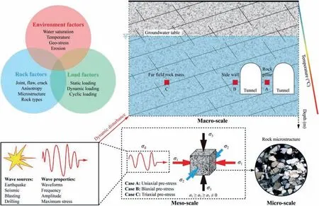
Fig.1. Overview of the influencing factors in rock engineering structures suffering from various cyclic loads.
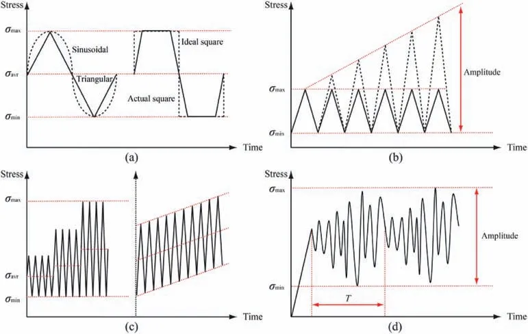
Fig. 2. Schematics of cyclic stress waveform and loading path: (a) Regular triangular, sinusoidal, actual and ideal square waveforms; (b) Waveforms with constant and stepwsie increasing amplitudes; (c) Waveform with multi-level cyclic amplitude and that with increasing average stress and constant amplitude; and (d) Random cyclic loading.
For cyclic loading tests,different loading waveforms and loading paths have been selected in previous literatures,as summarized in Fig. 2. Cyclic loading waveforms can be specified from regular periodic sinusoidal, square and ramp waveforms or random cyclic loads, and the definition of cycle loading parameters can be referenced in previous literatures. For different research purposes, the cyclic loading amplitude and average stress may be either constant or variable in experiments, such as the stepwise increasing amplitude (Heap et al., 2009; Li et al., 2019a), the multi-level amplitude cyclic loading (Jia et al., 2018; Yang et al., 2018a; Peng et al., 2020), the increasing average stress with constant amplitude(Yang et al.,2015;He et al.,2016;Kumar et al.,2018),and the random cyclic loading with varying frequency, amplitude and maximum cyclic stress(Liu et al., 2018a).
2.2. Based on frequency or fatigue life
Based on different cyclic loading frequencies F,cyclic tests can be classified as high frequency (F > 10 Hz), medium frequency(0.1 Hz
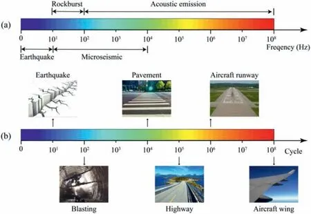
Fig. 3. Ranges of frequency and fatigue life of natural and human-caused events.
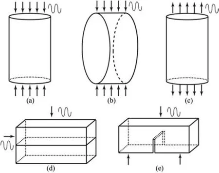
Fig.4. Schematics of different cyclic loading tests:(a)Cyclic uniaxial compression;(b)Indirect cyclic tension; (c) Direct cyclic tension; (d) Cyclic shear test; and (e) Cyclic flexural test.
2.3. Based on loading type
Based on the loading type applied on rocks, cyclic loading tests can be classified as cyclic uniaxial or triaxial compressive tests,cyclic tensile tests, cyclic shear tests and cyclic flexural tests, as shown in Fig. 4. Thereinto, cyclic uniaxial compressive tests are most widely conducted on rocks, generally corresponding to the practical stress circumstance of rock structures encountered (onedimensional(1D)cyclic loading)(Attewell and Farmer,1973;Bagde and Petroˇs, 2005a; Guo et al., 2012; Song et al., 2013a; Vaneghi et al., 2018). For rocks in the deep underground engineering involving mines, tunnels and caverns, the cyclic triaxial compressive tests are performed to simulate the actual three-dimensional(3D) stress state (Liu et al., 2011; Liu and He, 2012; Ma et al.,2013; Zhao et al., 2018a).
Since rocks under tensile loading are generally featured by lower resistance compared with that under compressive loading, cyclic tensile tests on rocks have been conducted (Coviello et al., 2005;Chen et al., 2013; Dai et al., 2013). Given the difficulties in experimental operation and specimen preparation,the direct cyclic tensile test has not been widely performed on rocks. Rather, the indirect cyclic Brazilian disc(BD)tests have been conducted for ascertaining the fatigue tensile resistance of rocks(Hudson et al.,1972;Wang and Xing,1999;Swab et al.,2011;Erarslan and Williams,2012).Recently,Liu et al. (2017a, 2018b) proposed an indirect cyclic tensile testing method employing flattened BD (FBD) specimens. The cyclic FBD testing method ensures a consistent contact boundary distribution since the contact regions rarely change during the entire loading/unloading process.Moreover,the central crack initiation,the crucial prerequisite for a valid Brazilian-type indirect tensile strength test,can be guaranteed(Liu et al.,2017a).
Compared with cyclic compressive or tensile tests on rocks,the cyclic shear test is usually conducted on rock joints since joints significantly affect the mechanical response of in situ rock masses(Jing et al.,1993; Lee et al., 2001; Ma et al., 2017; Niktabar et al.,2017; Kou et al., 2019). During the tests, a hydraulic jack is generally imposed upon the rock specimen top for achieving a vertical static constant normal loading, and a hydraulic actuator is applied on the shear blocks to obtain a horizontal cyclic shear loads(Fig. 4d). In addition, cyclic shear load can also be combined with cyclic normal load (superimposed on static normal load), which is generally conducted using more sophisticated shear box devices.
The flexural mechanism is vital for a reasonable programming and stability appraisal of rock structures. However, according to available literature,the cyclic flexural tests are mainly concentrated on concrete for design of pavements and railways, which are also named as three-point or four-point bending test (Singh and Kaushik, 2003; Li et al., 2007; Goel et al., 2012; Sohel et al., 2018)(Fig.4e).Until now,the mechanical responses of rocks subjected to cyclic flexural loading remains far from being thoroughly understood (Le et al., 2014).
2.4. Based on environment conditions
Considering that rocks exist in various environments (e.g.different humidities, temperatures or groundwater levels), researchers conducted cyclic wetting-drying tests or cyclic freezingthawing tests on rocks. As a crucial environmental factor accelerating regression of rocks, cyclic wetting-drying process can be induced by the variation of rainfall,vaporization and the change in groundwater and reservoir water levels (Mutlutürk et al., 2004;Shakoor and Barefield, 2009; Jiang and Niu, 2016). Due to the water-rock interaction,the effective pressure decreases during the wetting process and the cement in rocks weakens during the drying process,leading to strength reduction of rocks(Zhao et al.,2017,2018b;Xie et al.,2018;Sun and Zhang,2019).In addition,the cyclic freezing-thawing test is generally performed on water-bearing rocks in some low temperature areas (Chen et al., 2004; Tan et al., 2011; Liu et al., 2019; Li et al., 2019b). These rocks are susceptible to frost pressure and frost-heaving force induced by freezing and thawing of water in rocks.
3. Fatigue behavior of rocks under cyclic loads
Significant efforts have been devoted to acquiring mechanical behavior of rock suffering from cyclic loads over the past 60 years.This section focuses on reviewing and analyzing the representative results and outcomes observed from cyclic loading and unloading tests. Table 1 displays the research timeline of rock fatigue mechanism from 1960 to 2020. To summarize, investigation on the fatigue response of rocks has mostly concentrated on the following four aspects:
(1) How do the fatigue deformation and strength of rocks suffering from cyclic loading degrade, and what are the difference and connection between monotonic and fatigue deformation and failure behaviors of rocks?
(2) How to quantify the degradation of mechanical properties using a damage variable with definite physical significance,and what are the evolution features of fatigue energy parameters and accumulative damage?
(3) What is the progressive failure characteristic of rocks suffering from cyclic loads, regarding crack initiation, propagation and coalescence, and what is the fatigue failure mechanism?
(4) How does the cyclic loading affect the fatigue responses and their evolution features, in terms of loading waveforms and frequency, maximum stress and amplitude?
3.1. Strength and deformation characteristics
Some early experimental studies indicated that cyclically loaded rocks would fail in a limited number of cycles under the condition that the maximum cyclic loading is less than the uniaxial compressive strength of rocks (Burdine,1963; Brown and Hudson,1973). Fig. 5 shows some characteristic stress-strain curves ofdifferent rocks under cyclic uniaxial/triaxial compression (Ren et al., 2013; Peng et al., 2019), cyclic tensile loading (Liu et al.,2018b) and cyclic shear loading (Jafari et al., 2003). It can be observed that hysteresis loops exist in all cyclic stress-strain curves of rocks,and axial strain in each cycle can be divided into two parts,namely, elastic and plastic strains. The elastic strain can be recovered, whereas the plastic strain irreversibly increases with increasing cycle number. The accumulation rate of plastic strain is not constant, and there is more deformation accumulation in the first and last few cycles.For rocks under triaxial cyclic loading,the vertical strain is less than the lateral one,and the volumetric strain is positive in the first few cycles and then becomes negative, indicating that rocks are first compressed and then dilated until failure.
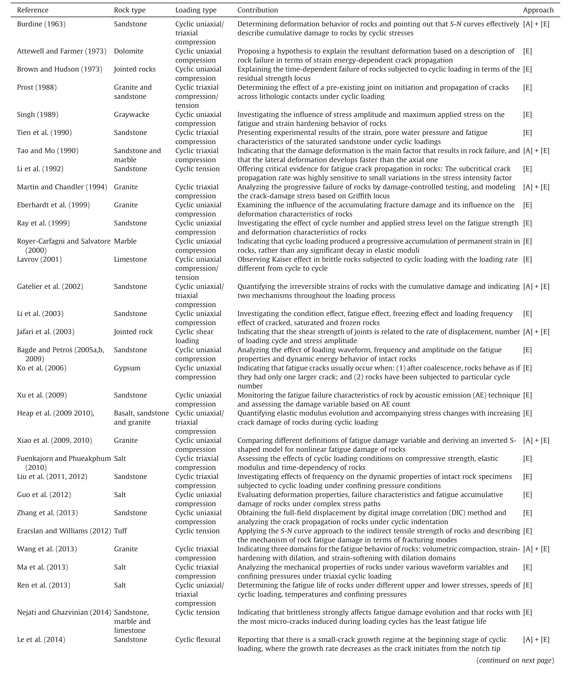
Table 1 Research timeline of the fatigue properties of rocks under various cyclic loading conditions (1960-2020).
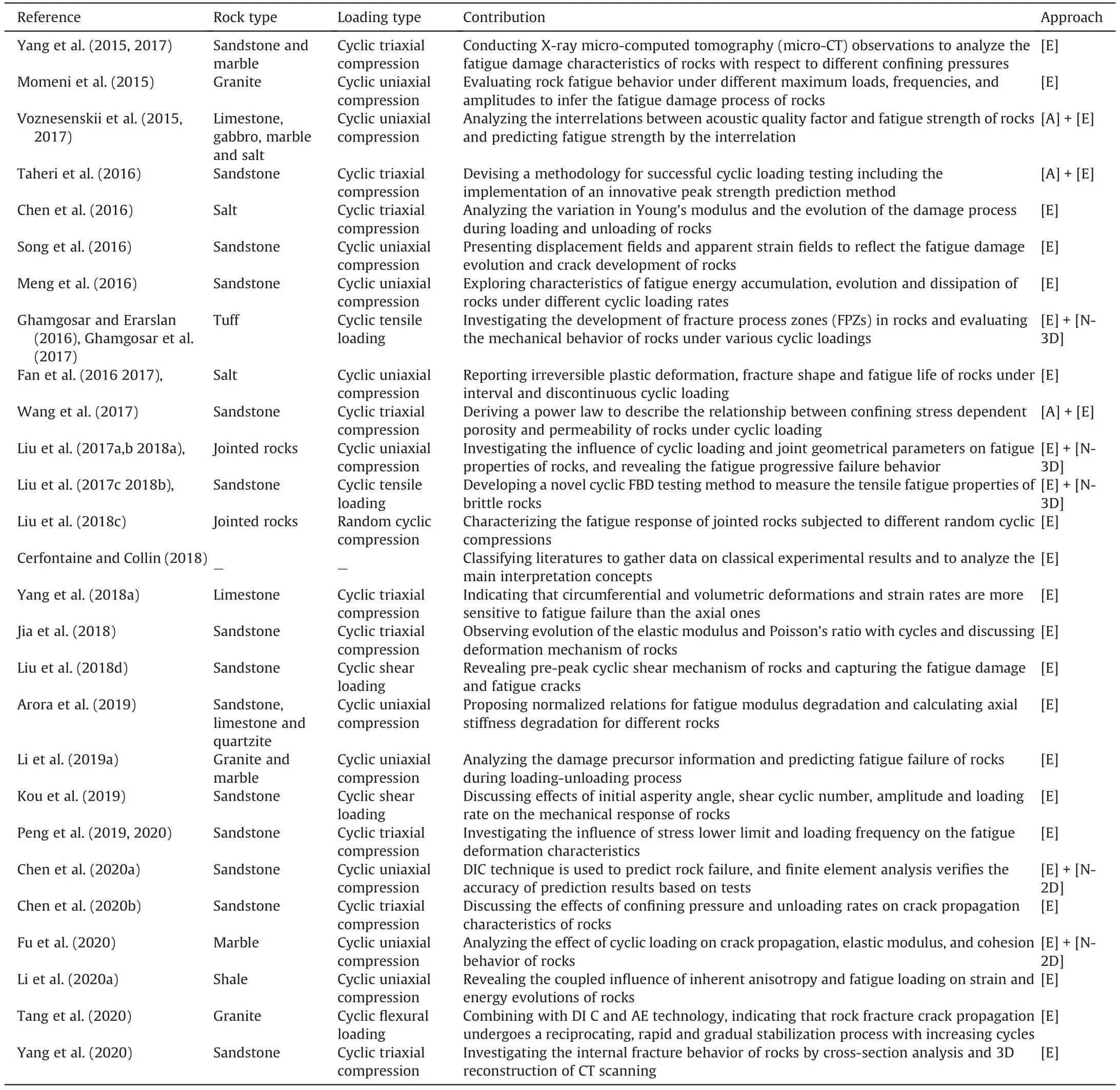
Table 1 (continued)
It is worth illustrating that the fatigue stress-strain curve of rocks subjected to cyclic uniaxial compression is closely associated with the static monotonic stress-strain curve.Brown and Hudson(1973)first illustrated the residual failure locus (Fig. 6a), and researchers further pointed out that there is a fatigue failure law for rocks under uniaxial cyclic loading (Fig. 6b). The terminal fatigue strain (i.e. the axial strain at the fatigue failure point in the cyclic stress-strain curve) of rocks is approximately equal to the post-peak monotonic strain (i.e. the axial strain at the point with the maximum cyclic stress in the post-peak portion of the static monotonic stress-strain curve) (Zhang et al., 2008; Guo et al., 2012; Liu et al., 2018c).Certainly, there are few deviations between the terminal fatigue strain of rocks and their post-peak monotonic strain due to the dispersion and microstructure of rock specimens, while the deviations between them are usually less than 10%. However, such fatigue failure law has not been observed for rocks under cyclic triaxail compression,cyclic tensile loading,or cyclic shear loading.
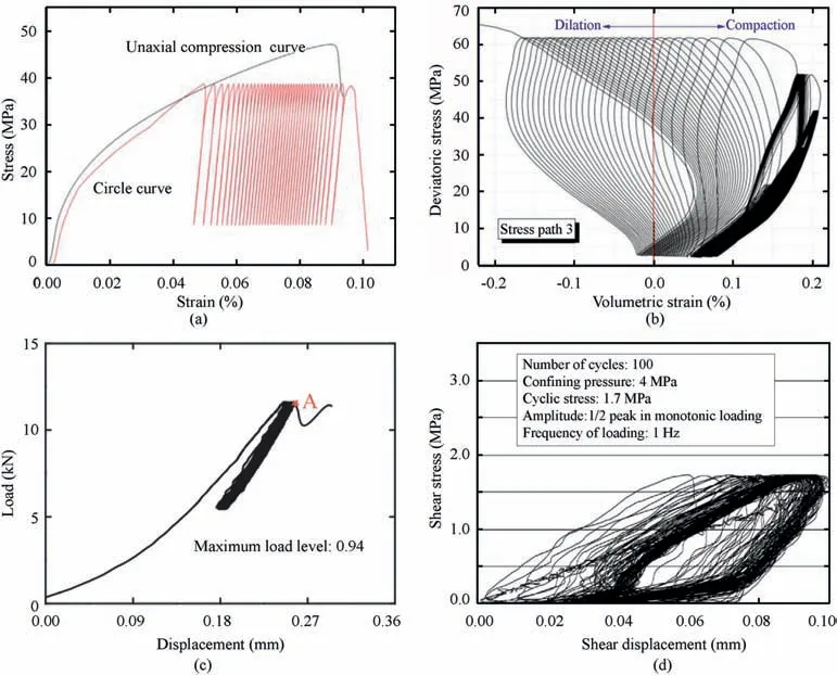
Fig.5. Representative stress-strain curves of rock suffering from cyclic loads:(a)Cyclic uniaxial compression(Ren et al.,2013);(b)Cyclic triaxial compression(Peng et al.,2019);(c)Cyclic tension (Liu et al., 2018b); and (d) Cyclic shear loading (Jafari et al., 2003).
Researchers also analyzed the axial irreversible plastic strain of rocks.As illustrated in Fig.7a,the development of axial irreversible strain of rocks under various cyclic loading conditions can be classified into three types. In most experiments, the irreversible strain develops like curve b featuring an obvious three-stage mode,namely, the initial, steady, and accelerated stages (Fig. 7a). In the initial stage, the axial strain rapidly develops owing to the closure of pre-existing voids or cracks in rocks,and then remains steady in stage II. This steady stage takes up most of the time of the whole cycle process,while corresponding accumulated irreversible strain only accounts for about 1/5 of the total strain. Eventually, the irreversible strain sharply increases in the accelerated stage and final fatigue failure of rocks.For brittle rocks under high maximum cyclic stress and amplitude, its irreversible strain usually develops like curve a; thereinto, the fatigue strain grows very quickly, and the three-stage development law can hardly be observed. Rocks under higher maximum cyclic stress and amplitude usually undergo fatigue failure after only a few cycles, characterized by low fatigue life.For rocks under lower maximum cyclic stress less than their fatigue failure threshold value, the development curve of irreversible strain is like curve c, featuring obvious initial and steady stages;after the initial stage,the fatigue strain keeps stable for a long cycling time. There is no accelerated stage during an entire cyclic loading and unloading process.
In addition, scholars also illustrated the deformation moduli of rocks suffering from cyclic loads in terms of Young’s modulus,secant modulus and tangent modulus. According to existing literatures, all these moduli usually exhibit similar three-stage evolution law like the development of irreversible strain, namely, the initial, steady, and accelerated stages. The deformation modulus increases or decreases rapidly during the first few cycles and then remains stable in stage II, eventually it decreases again in the accelerated phase. The steady stage takes up most of the cycling time during an entire loading-unloading process, and only the deformation modulus slightly degrades at this stage.Based on rock types,the evolution curves of fatigue deformation modulus can be systematized into four types (Fig. 7b). For hard rocks under high maximum cyclic stress and amplitude, its deformation modulus generally develops like curve a, featuring an obvious three-stage decrease trend. While for soft rocks or rocks containing many voids, the deformation modulus increases during the first few cycles due to closure of voids and hardening of specimens.When the maximum cyclic stress applied on rocks is below the fatigue failure threshold value, the evolution of deformation modulus is like curves c and d, in which only the initial and steady stages can be observed.
For cyclic triaxial compression tests,the irreversible volumetric strain is one of the key quantities related to the dilatancy effects of rocks. Fig. 8a shows the development curves of irreversible volumetric strain of rocks suffering from cyclic loads with different confining pressures(Liu and He,2012).The irreversible volumetric strain is positive in first few cycles and then becomes negative,indicating that the rock specimen is first contracted and then dilated until fatigue failure.The irreversible volumetric strain at the dilatancy point increases with increasing confining pressure.Fig.8b depicts the evolution of fatigue deformation modulus of rocks under different triaxial cyclic loads (Ma et al., 2013). Rocks under higher confining pressures are characterized by higher initial fatigue modulus, and the fatigue deformation modulus degenerates more slowly than that under lower confining pressures.
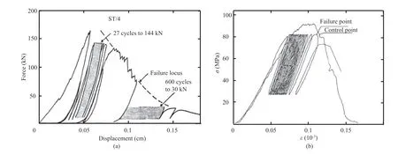
Fig. 6. Stress-strain curves of rocks measured from monotonic and cyclic load tests, reproduced from (a) Brown and Hudson (1974) and (b) Xiao et al. (2009).
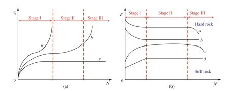
Fig. 7. Schematics of classification in development curves of axial irreversible deformation (εi) and fatigue deformation modulus (E).
3.2. Fatigue energy parameters
Recently,the energy characteristics of rocks under cyclic loading were analyzed,in which energy density parameters are determined by the integration of relevant cyclic stress-strain curves (Solecki and Conant, 2003; Meng et al., 2016; Zhang et al., 2017a; Liu et al., 2017b, 2018c).
Bagde and Petroˇs (2009) pointed out that the dynamic energy accumulated in rocks under cyclic loading conditions can be considered as an important indicator significantly influencing the fatigue failure mechanism of rocks. Some researchers further investigated the fatigue energy characteristics of rocks. The evolution of total, elastic and hysteresis energies of rock is illustrated in Fig. 9a. Corresponding to the development of irreversible strain of rocks, the evolution of fatigue energy parameters in each cycle can be divided into three stages. In the first few cycles, most of stored energy converts to the released elastic energy, and the hysteresis energy is dissipated for the closure of micro-cracks or voids in rocks and hardening of rocks. Afterwards, the total energy absorbed slightly decreases and fluctuates within a small range for a long cycling time, during which the released elastic energy remains nearly constant, and only a little bit of hysteresis energy is dissipated for the initiation, propagation and coalescence of micro-cracks. Eventually, the stored total energy in each cycle increases again, and the proportion of dissipated hysteresis energy increases for the structural failure of rock. The development of accumulated energy characteristics of rocks during an entire cyclic loading test is illustrated in Fig. 9b (Meng et al.,2016), in which all the energy parameters increase nonlinearly before the fatigue failure occurs. The elastic energy reaches the peak at the fatigue failure point, and then dramatically decreases.The instantly released elastic energy mainly transforms into surface energy related to crack coalescence and kinetic energy for structural fatigue failure of rocks, resulting in a sharp increase of dissipated hysteresis energy. It can thus be concluded that the energy release is the inherent motivation of the structural failure of rocks, and that there is a certain storage limitation of elastic energy for a given rock. Rocks are cyclically failed once the stored elastic energy exceeds its limitation.
For rocks under cyclic triaxial compression, the evolution of energy characteristics is similar to that under cyclic uniaxial compression, as shown in Fig.10a (Zhang et al., 2017a). Before fatigue failure, the stored total energy mainly convers to the elastic energy, and both elastic and hysteresis energies increase with increasing fatigue deformation.
As the elastic energy reaches its maximum,the fatigue failure of rocks occurs,resulting in a remarkable decline of elastic energy and a drastic increase of hysteresis energy.The dissipated and released energies mostly convert to kinetic energy, surface energy and frictional energy for the extension and connection of cracks and the formation of fracture surfaces.Ultimately,the elastic and hysteresis energies decrease to residual values as the fatigue deformation develops to the residual stage.Additionally,the energy magnitudes are dependent on the confining pressure. Rocks under higher confining pressure are featured by higher energy storage limitation,residual elastic energy and maximum dissipated energy (Fig.10b).
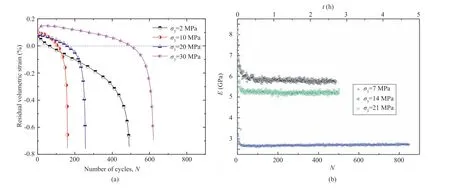
Fig. 8. Development of irreversible volumetric strain and fatigue deformation modulus of rocks subjected to different triaxial cyclic loads, reproduced from (a) Liu and He (2012)and (b) Ma et al. (2013).
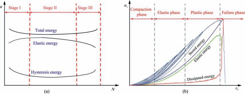
Fig.9. (a)Schematics of the evolution of total energy,elastic energy and dissipated hysteresis energy in each cycle;and(b)Development of accumulated energy characteristics of rocks during an entire cyclic loading test (Meng et al., 2016).
3.3. Fatigue damage evolution
Under external loading,micro-cracks or micro-voids are usually generated in rocks before the emergence of macro-fractures, and the initiation and growth of micro-cracks and micro-voids are defined as damage(Martin and Chandler,1994).For rocks suffering from cyclic loading, the fatigue damage is induced by the accumulation of tiny irreversible damage in each cycle. The physical quantity used to characterize such irreversible damage is called fatigue damage variable(Lemaitre,1996).Since the fatigue damage induces the degeneration of many mechanical properties of rocks involving the strength,stiffness,hardness,wave velocity,electrical resistance and so on,the fatigue damage variable can be defined by various methods.Several typical definition methods were reported in previous literatures,including definitions with acoustic emission(AE) accumulative counts, ultrasonic wave velocity, energy dissipation, maximum strain and elastic modulus (Li et al., 2019a; Sun and Zhang, 2019; Xiao et al., 2010; Xu et al., 2009), and corresponding calculation formulae are summarized in Table 2. No matter which definition method is adopted,the evolution of fatigue damage should accord with the initiation, propagation and coalescence of micro-cracks (Eberhardt et al.,1999).A rational fatigue damage variable should not only have an explicit physical meaning,but also reflect the real degradation behavior of mechanical characteristics of rock.
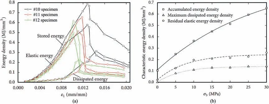
Fig.10. (a)The evolution of energy density characteristics for rocks under cyclic triaxial compression;and(b)The effect of confining pressure on energy characteristics(reproduced from Zhang et al., 2017a).
Xiao et al. (2010) calculated the damage variable of granite under cyclic uniaxial compression.The merit and demerit of several typical definition methods are compared,as depicted in Fig.11.For elastic modulus approach,the elastic moduli of rocks suffering from static monotonic loading are generally regarded as the initial modulus since it is difficult to determine the initial dynamic modulus.However,the static modulus of rocks is not always larger than the dynamic one during whole cycle process,and thus fatigue damage variable may be negative, which violates the damage theory. In addition, although the elastic modulus method has evident physical significance, the determination of deformation modulus is subjective,and thus the calculation of damage may not be precise.Similarly,although the ultrasonic wave velocity of rocks under cyclic loading exhibits an evident three-stage attenuation characteristic(Fig.11a),consisting with the degradation behavior of irreversible strain and fatigue deformation modulus, the original ultrasonic wave velocity is complicated to be obtained in laboratory tests. Additionally, the ultrasonic wave velocity is unequal to 0 when the fatigue failure occurs, and thus the final damage variable is not equal to 1, but varies with rock types. Therefore, the virtues of ultrasonic wave velocity method are masked by its defects.The evolution curve of fatigue damage variable defined with maximum and residual strain methods are depicted in Fig.11b. It seems reasonable to divide the development of damage variable into three phases,and that the final damage is equal to 1 when the fatigue failure occurs. However, it is worth noting that the initial damage variables calculated by these two methods are 0.82 and 0.67, respectively, which are fairly large. Both the maximum and residual strain methods magnify the premier value of damage while underestimate the damage accumulated in the whole cycle process. Since the internal damage of rocks is induced by the dissipated hysteresis energy, calculating fatigue damage variable from the perspective of energy dissipation offers a new insight,and the corresponding results are also depicted in Fig.11b. An evident three-stage evolution of fatigue damage variable can be observed,which reflects degradation of fatigue deformation characteristics,and the final damage variable is equal to 1 when the rock cyclically fails. Accordingly, the energy dissipation method is reasonable to describe the evolution of damage variable. In addition, since AE connects with the quick release of strain energy of rocks induced by plastic deformation and crack propagation, the AE cumulative counts method is also employed for illustrating the fatigue damage.Similar to the evolution of damage variable calculated by dissipated hysteresis energy, the fatigue damage based on AE cumulative counts accumulates from 0 to 1 following the three-stage manner.Nevertheless, the AE signals are highly susceptible to environmental noises,which may not be accurate enough to calculate the fatigue damage variable.
According to the above analysis, although these definition methods are capable of elucidating the degradation resonse of rocks suffering from cyclic loads, it may be more appropriate to define the fatigue damage variable by the energy dissipation method. The damage evolution of rocks defined with different methods was further investigated(Xiao et al.,2009;Xu et al.,2009;Guo et al., 2011; Liu et al., 2012; Yang et al., 2018b; Gao and Feng,2019). Fig. 12 displays the process of fatigue damage variable for different rocks, in which an inverted-S shaped curve with three phases is observed. According with the development of fatigue deformation characteristic, fatigue damage quickly accumulates in the first few cycles because of the closure of pre-existing void in rocks;afterwards it uniformly develops for a long cycling time and sharply accumulates again when the fatigue failure occurs. In addition,the magnitude of fatigue damage variables is affected by a few factors such as cyclic loading parameters, rock types, and environmental aspects, which are discussed in the next section.
One by one, in the early morning darkness, my eighth-graders and I boarded the bus. When Robbie Brown got on, he was holding a four-inch pot with a white hyacinth. The delicate flowers were in full bloom. There was a small American flag stuck in the soil. Everyone asked Robbie what the flower was for. All he d say was that he was on a mission.
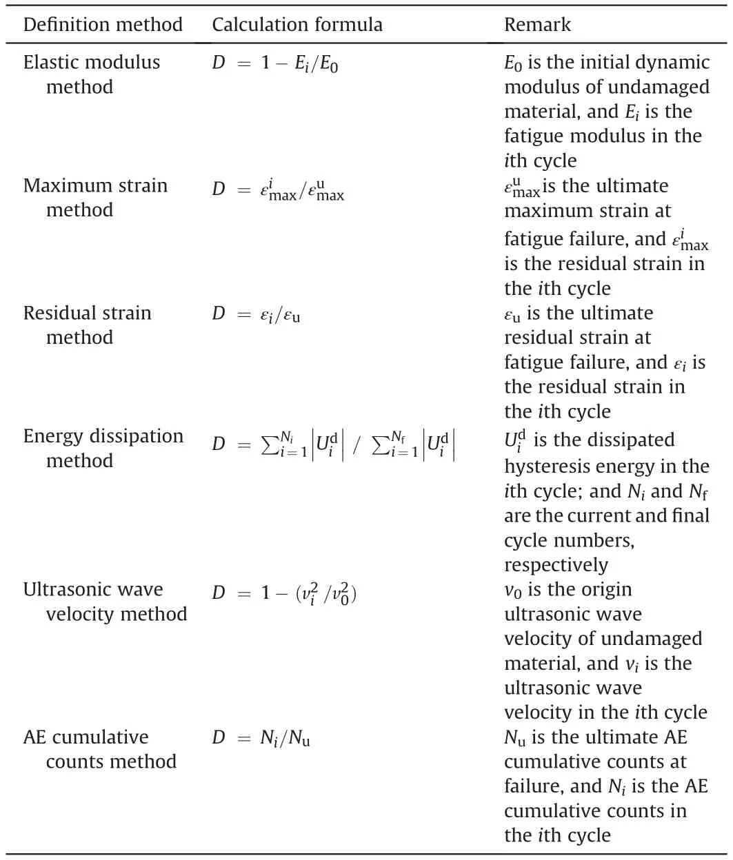
Table 2 Calculation method of fatigue damage variable of rocks under cyclic loading.
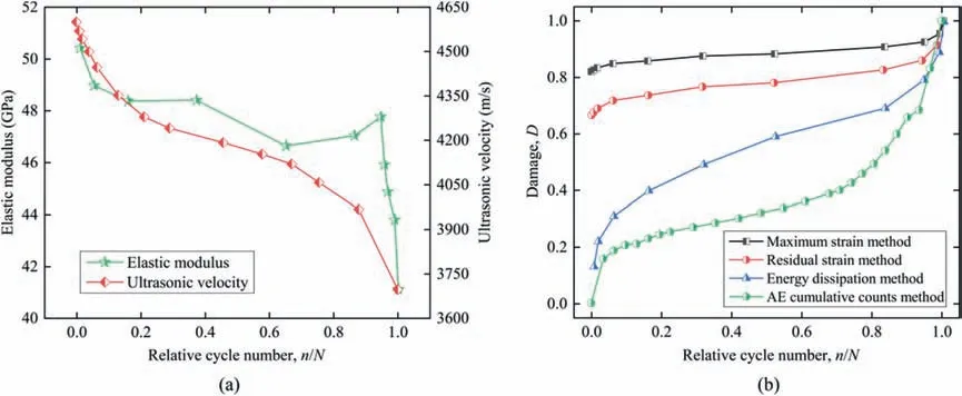
Fig.11. (a) The development of elastic modulus and ultrasonic wave velocity of rocks during an entire cyclic loading test; and (b) The evolution of accumulated fatigue damage variable defined with different methods, reproduced from Xiao et al. (2010).
3.4. Fatigue failure behavior and indicator
Because the mechanical responses of rocks under dynamic loading are distinct with that under static loading(Du et al.,2020;Li et al.,2020b,2021;Pei et al.,2020;Jiang et al.,2021a),the fatigue failure characteristics of rocks under cyclic loading has been analyzed. Compared with the static failure modes of rocks under monotonic loading, fatigue failure of rocks under cyclic loading usually occurs more shortly.More squashed rock flinders and wider crack bands are generated in the cyclically failed rock specimens,as shown in Fig. 13 (Liu et al., 2012, 2018c; Ghamgosar et al., 2017;Yang et al.,2017).The fragmentation degree is related to the cyclic loading parameters, which are analyzed in detail in Section 4.Specially,the localized shear fracture bands exist in the failed rocks under cyclic triaxial compression, and the shear fracture angle reduces as the confining pressure increases. Employing the X-ray micro-computed tomography (micro-CT) apparatus, Yang et al.(2015) further demonstrated that rock specimens under cyclic loading are featured by more complex crack flats compared with that under monotonic loading, and both the crack region and aperture range in cyclically failed rocks surpass those in monotonically failed rocks (Fig.14).
As an effective approach for nondestructive examination,the AE technology is diffusely applied for investigating the failure behavior of rocks under various loading conditions including compression,tension, shearing and fracture (Zhang et al., 2015, 2019; Moradian et al., 2016; Ren et al., 2020; Jiang et al., 2021b). The AE characteristics of rocks are barely studied in cyclic tests with constant amplitude and large cycle number, but generally monitored under cyclic loads with increasing maximum stress(Meng et al.,2018;Li et al., 2019a; Tang et al., 2020; Yang et al., 2020). Researchers pointed out that for a single loading-unloading cycle,the AE counts always increase gradually in the loading stage while decrease in the unloading process(Fig.15a).The most active AE events occur near the maximum cyclic stress in each cycle.It is worth noting that the AE events are monitored almost from the beginning of the loading stage in the first cycle,while only a few AE events are captured at a subsequent cycle stage as the axial stress is below the last maximum stress; after the cyclic stress surpasses the maximum stress in previous cycle, the AE counts rapidly increase until the stress reaches a new maximum value.This phenomenon is known as the Kaiser effect(Kramadibrata et al.,2011;Lehtonen et al.,2012;Hsieh et al., 2015; Singh et al., 2018). As cycle number rises, the maximum AE counts in each cycle increase, and the frequency at which violent AE events in a single cycle appears becomes higher,indicating that more cracks form and more damages accumulate in rocks.Therefore,more and more AE events appear before the stress reaches the previous maximum cyclic stress,which is known as the Felicity effect (Zhang et al., 2017b, 2018; Tian et al., 2020). Meng et al. (2018) also compared AE features of rocks under static loading.They demonstrated that the static failure behavior of rocks differs from that under cyclic loading condition, as shown in Fig.15b.
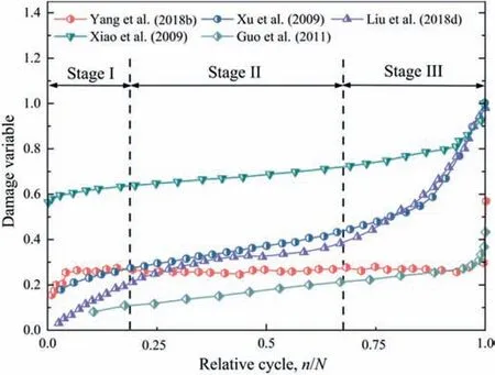
Fig. 12. Evolution curves of accumulated fatigue damage variable for different rocks under cyclic loading (data from Xiao et al., 2009; Xu et al., 2009; Guo et al., 2011; Liu et al., 2012; Yang et al., 2018b).
As another effective experimental method, digital image correlation (DIC) technique is resoundingly implemented for investigating progressive failure of rocks under different loading conditions by recording offset fields of rock surface (Field et al.,2004; Pan et al., 2009; Lin and Labuz, 2013; Yan et al., 2020). This approach owns some obvious merits(Gao et al.,2015;Munoz et al.,2016; Xing et al., 2018; Chen et al., 2020a) and thus has also been employed to study the progressive failure of rocks under cyclic loading (Song et al., 2013b, 2016; Tang et al., 2019). Fig.16 depicts the displacement fields of sandstone under cyclic uniaxial compression at some crucial loading points obtained by DIC.It can be observed from horizontal displacement fields that the crack between blue and red zones occurs at point D21,and soon becomes more and more apparent near the fatigue failure point. However,the variation of vertical displacement fields is not noticeable from points D21 to D23.
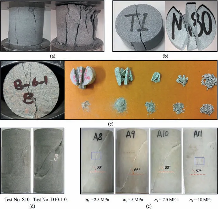
Fig. 13. Failure modes of different rocks suffering from static monotonic loading and cyclic loads (a) from our laboratory tests, and (b-e) reproduced from Liu et al. (2018b),Ghamgosar et al. (2017), Liu et al. (2012), and Yang et al. (2017), respectively.
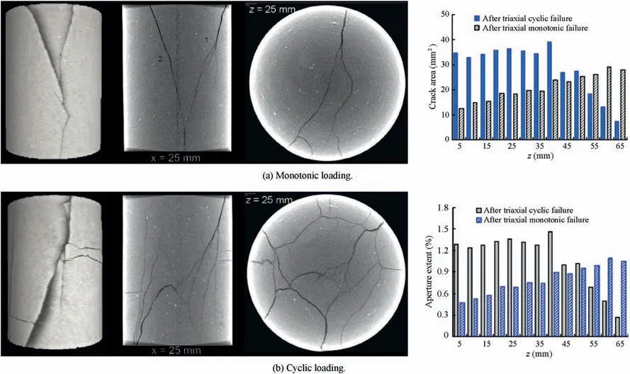
Fig.14. Comparison of X-ray CT scanning surface images and evolution of crack area and aperture extent of rocks under monotonic and cyclic loading(reproduced from Yang et al.,2015).
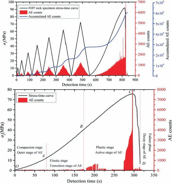
Fig.15. Comparison of stress,AE counts,accumulated AE counts during the monitoring duration of rocks suffering from cyclic and monotonic loads(reproduced from Meng et al.,2018).
For providing further insight in progressive failure behavior of rocks, some numerical simulation methods are applied, such as finite element method(FEM)(Haeria et al.,2014;Wang et al.,2014;Wei et al., 2016a,b), finite difference method (FDM) (Yan and Fu,2014; Itasca, 2016; Chang and Konietzky, 2018), and discrete element method (DEM) (Hazzard et al., 2000; Abe et al., 2004;Potyondy and Cundall,2004;Invernizzi et al.,2013;Xu et al.,2016).The robustness of these numerical methods has been validated for modeling crack propagation and failure patterns, as well as for simulating AEs generated during rock fracture under various loading conditions (Bahaaddini et al., 2015; Dai et al., 2016; Du et al., 2017). Differing from the numerical monotonic loading tests, the simulation of cyclic loading tests is more complicated since the degradation behavior of strength and stiffness of rocks during the loading and unloading processes should be considered(Sadd et al., 1993; Peng, 2014; Wang et al., 2020). So far, the simulation of the progressive fatigue process of rocks is rather limited(Liu et al.,2017c,2018b;Fu et al.,2020).Recently,Liu et al.(2018b)numerically studied the cyclic tension tests by secondarily developing a DEM open source code.A micro-stiffness and strength reduction calculating approach for DEM relationship is proposed to simulate irreversible plastic deformation and hysteresis loops of rocks accumulated during whole cycle process; and then the progressive fatigue failure behaviors of rocks are numerically observed by recording the spatio-temporal evolution of micro-cracks. They pointed out that compared to failure process of rocks under static loading,fatigue progressive fracture takes place more abruptly with unobvious precursor signs.Fig.17 depicts the inner failure features of sandstone subjected to cyclic tension in the view of central crosssection of DEM model and the spatial distribution of micro-cracks in the stereo insight, and Fig.18 quantitatively describes the evolution of micro-cracks represented by the number of broken bonds in DEM model.It is evident that fatigue fracture process of rocks is featured by a three-stage mode,namely,initial stage(i.e.before 20%fatigue life),steady stage(i.e.20%-80%fatigue life)and accelerated stage(i.e.after 80%fatigue life).The initiation of micro-crack inside the DEM model is mainly concentrated at the accelerated phase,during which new cracks initiate and propagate sharply, and then quickly integrate with previous micro-cracks,forming macroscopic failure zone or surface. The micro-cracks enter the unsteady propagation stage,and eventually trigger the sudden fatigue failure of DEM model.Note that the micro-cracks inside rocks always occur during the loading process, rather than the unloading process.
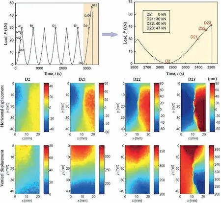
Fig.16. Apparent strain fields of rock specimen at specified points during the final cyclic loading stage (reproduced from Song et al., 2016).
Note that although the failure behavior of rocks under cyclic loading has been revealed from both macro and micro insights,an appropriate indicator is still vital for predicting the fatigue failure of rocks. However, it is difficult to define a failure indicator with distinct physical significance and threshold value. Recently, Song et al. (2018) proposed dimensionless hysteresis energy-based failure indicators for concrete and brittle rocks under fatigue loading,and a two-step approach to predict the failure of concrete was introduced. Different multi-level cyclic loading strategies were designed to verify their approach, and results depicted that the hysteresis occurrence ratio(HOR)and hysteresis energy ratio(HER)considering the hysteresis characteristics and dissipated energy are reliable failure indicators.Since the critical values of HOR and HER are material specific parameters, different cyclic loading tests are required for different rocks to obtain the specific values.
3.5. Influence of cyclic loading on the fatigue mechanism of rocks
Cyclic loading waveform, maximum cyclic stress, frequency and amplitude significantly influence the fatigue mechanism of rocks.Bagde and Petroˇs (2005b) conducted cyclic uniaxial compression tests with sinusoidal,ramp and square waveforms on rocks,and they evaluated the influence of cyclic loading waveforms on fatigue deformation and energy characteristics (Fig.19). Rocks under cyclic loading with a square waveform are featured by lower fatigue strength and stiffness and higher fatigue energy compared with that under cyclic loading with a sine or ramp waveform.Fig.20 depicts the influence of cyclic loading frequency on the mechanical characteristics of rocks,including the axial irreversible strain,fatigue deformation modulus, development of energy and damage, fatigue life and failure behavior. The accelerated stage of irreversible strain curves is more obvious for rocks under a lower loading frequency,and the irreversible strain increases with an increasing frequency,while thefatiguedeformation modulusdecreases.Sincethe loading time on rocks is less under a higher frequency,the total energy absorbed from external loads decreases,and the hysteresis energy is less dissipated,and thus fatigue damage declines while fatigue life rises.
Fig.21 depicts the influence of maximum cyclic stress on fatigue response and fracture behavior of rocks. Rocks under higher maximum cyclic stress are characterized by lower irreversible axial strain and higher fatigue deformation modulus. The area of hysteresis loop rises with growing maximum cyclic stress,and thus the total energy absorbed from external load increases, and elastic energy and hysteresis energy increase; as a result, fatigue damage increases while fatigue life declines. Besides, the average cyclic stress applied on rock specimen becomes higher with increasing maximum cyclic stress, and thus it is easier for cracks to develop and coalesce; in result, fatigue failure of rock specimen under higher maximum stress becomes more intense, and more broken rock debris is generated.
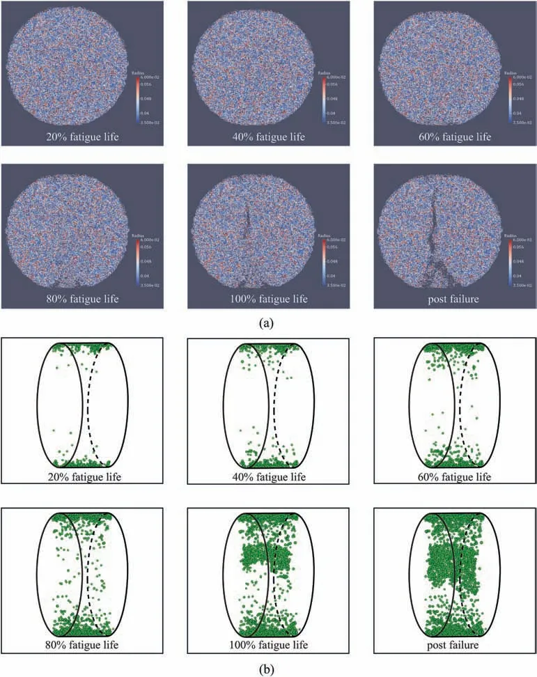
Fig.17. (a)The internal failure behavior of sandstone subjected to cyclic tensile loads in the view of central cross-section of DEM model;and(b)The spatial development of microcracks from a stereo viewpoint (reproduced from Liu et al., 2018b). Unit of radius in mm.
Fig.22 depicts the influence of cyclic load amplitude on fatigue response and fracture characteristics of rocks. With increasing loading amplitude, the minimum stress decreases since the maximum cyclic stress is fixed,and thus the duration of high stress causing the plastic deformation decreases, leading to the decrease in the irreversible strain and the increase in fatigue deformation modulus.Besides,an increase in the maximum load also induces an increase in hysteresis loop;hence, there is an upward trend in the total energy absorbed from external load and dissipated hysteresis energy. In this case, rocks under higher loading amplitude are featured by higher fatigue damage and shorter fatigue life. Since there is more dissipated energy in the whole cycle process,fatigue fracture of rocks under higher loading amplitude is more thorough with more rock fragments. It is noted that the fatigue life of different rocks increases with increasing loading frequency or decreasing maximum cyclic stress and cyclic loading amplitude in an exponential way, and many equations for lifetime prediction of different rocks have been obtained. In general, there are two approaches used to predict lifetime of rocks: the phenomenological method and the damage theory.
4. Constitutive relationship for rocks under cyclic loading
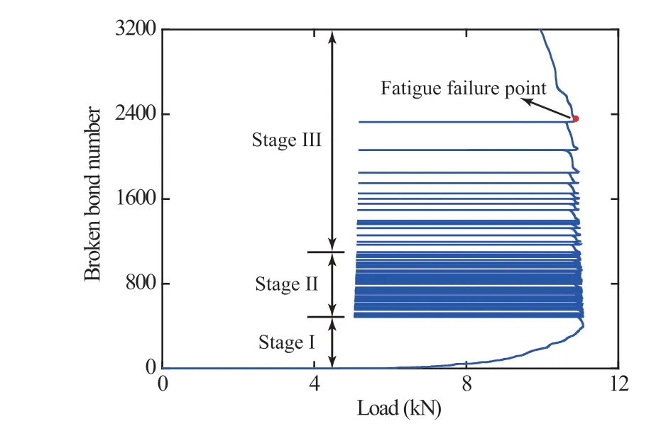
Fig. 18. Relationship between micro-crack number and axial load gained from numerical cyclic FBD test, reproduced from Liu et al. (2018b).
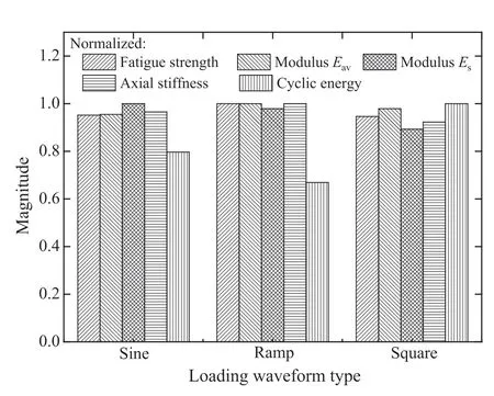
Fig.19. Influence of load waveform on fatigue response of sandstone, in terms of fatigue strength,axial strain and stiffness,and cyclic energy(reproduced from Bagde and Petroˇs, 2005b).
According to available literatures, the qualitative dependence of fatigue response of rocks on cyclic loads was well analyzed,while investigation on the quantitative relation between cyclic stress and strain of rocks is still rather limited.This relation is the so-called constitutive relationship. Because the constitutive model of rock sets the background for reasonable layout and stability analysis of rock structures (Sloan et al., 2013; Taheri and Tatsuoka, 2013; Pourhosseini and Shabanimashcool, 2014), some progress in the fatigue constitutive model has been made for describing the nonlinear mechanical characteristics of rocks under cyclic loading. Representative fatigue constitutive models of rocks are discussed in this section, and the main progress is summarized in Table 3.
4.1. Elastoplastic models
Constructing a constitutive framework based on the classical elastoplastic theory is a primary approach for reproducing fatigue properties of plastic materials subjected to cyclic loading(Simo and Ju,1987;Runesson and Mroz,1989;Lee and Fenves,1998;Tsutsumi and Hashiguchi, 2005). Cerfontaine et al. (2017) presented an elastoplastic constitutive relationship on the basis of a bounding surface concept dedicated to reproduce the internal fatigue behavior of rocks under low confinement. Thereinto, kinematic hardening of yield surface is used to simulate the cycles, and the isotropic emollescence on cohesion variable induces strength degradation of rocks, and they introduced a limit surface with a lower opening than the bounding surface to describe the peak strength of rocks. Fig. 23a shows a comparison of stress-strain curves of rock from laboratory test and calculated by this elastoplastic model. It can be observed that this model can reflect the cyclic behavior of rocks, while independently distinguishing the influence of each cycle is rather difficult. Zhou et al. (2019a) proposed a sub-loading surface model (SBSM) for rocks under cyclic loading based on a modified Drucker-Prager yield criterion, in which a corner model considering the strength characteristics of rock under triaxial tension or compression is introduced.Hashiguchi (2005) and Tsutsumi and Hashiguchi (2005) originally employed the SBSM to account for soils or metals subjected to cyclic loads; therewith, this concept is extended to concrete and soft rocks (Khosroshahi and Sadrnejad, 2008; Fu et al., 2012). The basic assumption of the SBSM is that a sub-loading surface exists inside normal yielding plane,and the nearest stress point is located in sub-loading surface. Different from traditional elastoplastic models, the change in the elastoplastic stage of SBSM is smooth.The stress-strain curves obtained from experiments and calculated by this SBSM are compared in Fig.23c.It can be concluded that this model is effective to reflect hysteresis loops and plastic deformation of rocks under cyclic loading.
4.2. Internal variable model
Since an existing yield surface is the precondition of conventional plasticity theory,employing this theory in various rock engineering issues may beinadequate,of which theyield surfacemayshrinkinto a point immediately once loading begins(Taoand Mo,1990).Therefore,endochronic theory with an internal state variable is employed to describe the fatigue properties in the framework of irreversible thermo-dynamics without complicated yield surface and loading functions (Rice, 1971; Collins and Houlsby, 1997). Taking the irreversible axial strain as an internal variable, Wang et al. (2013) first proposed an equation to illustrate the evolution of fatigue deformation modulus of rocks in cycle process,in which the deviatoric stress and confining pressure are taken into consideration. Fig.24a shows the relationship between cycle number and calculated deformation modulus of rocks,and a logical agreement between theoretical and testing results is obtained. By introducing the internal variable into the statistical damage theory,Zhou et al.(2017)proposed the statistical damage constitutive model with Weibull distribution for rocks suffering from cyclic loading. In this model, the non-uniformity of mesoscopic structures of rocks is considered,and only rock parameters that are readily acquired in laboratory tests are required.Stressstrain curves of rocks gained from laboratory tests and calculated by thisinternalvariablemodelarecomparedinFig.24b,andareasonable consistency can be observed.Note that although the internal variable theory is available for illustrating the degradation behavior of fatigue deformation of rocks, the loading and unloading stages must be separatelyconsidered,andhysteresisloopcannotbewellreflected.By defining a novel initial value of the axial strain, Liu and Dai (2018)further improved the internal variable equation and presented a fatigue damage constitutive relationship for reproducing the entire hysteretic loops and cumulative fatigue plastic deformation of rocks suffering from cyclic loading. Their model synthetically considered the coupled damage from macro-joints and micro-flaws in rocks,and the mechanical properties and geometric coefficient of joints are synchronously reflected. Moreover, a compaction coefficient is introduced in this model for describing the impaction phase in the first cycle.Fig.24c-f compares the experimental and theoretical results,and a rational consistency is observed in the light of the cyclic stress-strain curves and fatigue deformation.
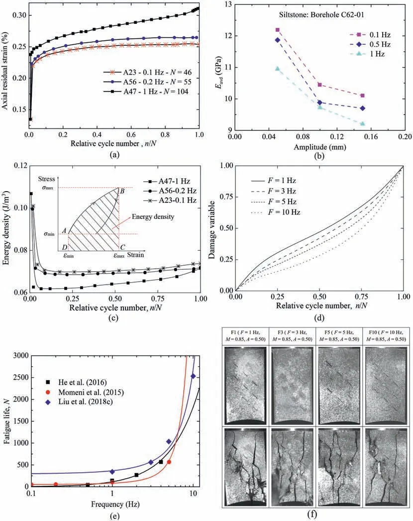
Fig. 20. Influence of cyclic load frequency on fatigue response of sandstone, in terms of axial irreversible strain, fatigue deformation modulus, elastic energy, damage variable,fatigue life and failure behavior(data from Bagde and Petroˇs,2009;Momeni et al.,2015;He et al.,2016;Liu et al.,2018c),in which A and M are the amplitude level and maximum stress level, respectively.
4.3. Energy-based damage model
Since the deformation and failure of rocks are generally accompanied with energy dissipation, establishing a constitutive model from the perspective of energy is a new insight that combines the energy dissipation and damage evolution with the mechanical properties of rocks(Ye and Wang,2001;Song et al.,2012;Zhou et al., 2019b). By introducing the fatigue damage variable calculated with energy dissipation method into the Lemaitre strain equivalence hypothesis(Lemaitre,1985),Liu et al.(2016)presented a fatigue damage constitutive relationship for cyclically loaded rocks,and a compaction parameter was introduced to quantify the compaction degree of rocks, which is less than 1 during the first loading stage, and afterwards equals 1. Fig. 25 compares the cyclic stress-strain curves obtained from experiments and that calculated by this model.It can be concluded that the modified damage constitutive relationship can accurately reflect the compaction of rocks, and hysteretic loops of rocks can be reproduced.
4.4. Discrete element-based model
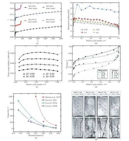
Fig.21. Influence of maximum cyclic stress on fatigue response of sandstone,in terms of axial irreversible strain,fatigue deformation,elastic energy,damage variable, fatigue life and failure behavior (data from Xiao et al., 2010; Guo et al., 2011; Song et al., 2013b; Momeni et al., 2015; Fan et al., 2016; Liu et al., 2018a,b; Yang et al., 2018b).
The above constitutive relationships belong to continuumbased approaches. Since DEM has distinctive merits in more realistically reproducing the grain shapes and interactions (Potyondy and Cundall, 2004), the DEM-based constitutive model has been proposed for brittle materials including rock and concrete.Considering the time-dependent behavior, Potyondy (2007) first proposed a parallel-bonded stress corrosion (PSC) model to simulate creep and static fatigue behavior of rock-like materials by adding a damage-rate law into the bonded-particle model (BPM)under the framework of DEM.Recently,Liu et al.(2017c)developed a DEM-based reduction model of stiffness and strength, and effectively reproduced the hysteresis loops and the accumulative plastic deformation of jointed rocks in the cyclic loading and unloading process. Sinaie et al. (2018) proposed a micromechanical damage model based on DEM for concrete under cyclic loading, in which the stress-reversal was formulated for interparticle bonds and the residual strength in terms of damage can be reliably predicted. Furthermore, a nonlinear parallel-bonded stress corrosion (NPSC) model and a multi-level stress corrosion model (MSC) model were established by Song et al. (2019a, b) for brittle geomaterials under fixed and multi-level cyclic loads,respectively. Fig. 26 compares the stress-strain curves measured by experiments and simulations by the two models.
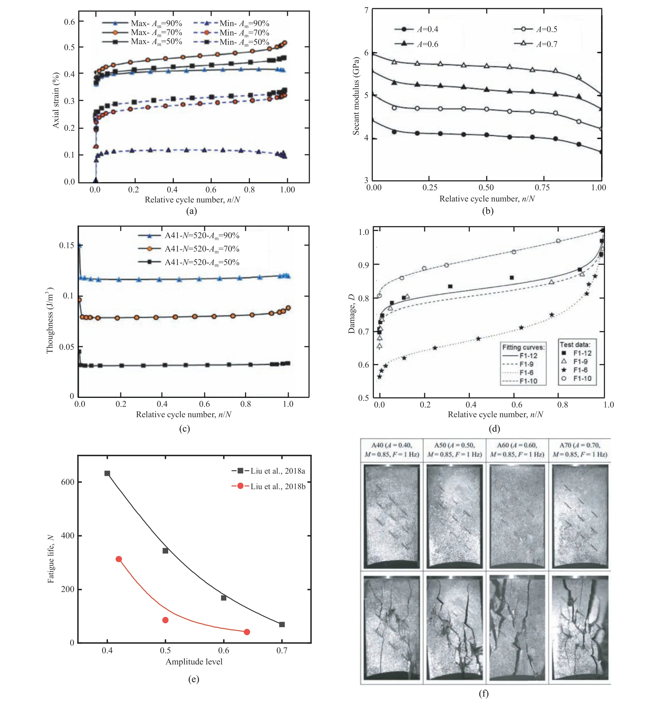
Fig.22. Influence of cyclic loading amplitude on fatigue response of sandstone,in terms of axial irreversible strain,fatigue deformation,elastic energy,damage variable,fatigue life and failure behavior (data from Xiao et al., 2010; Momeni et al., 2015; He et al., 2016; Liu et al., 2018a,b).
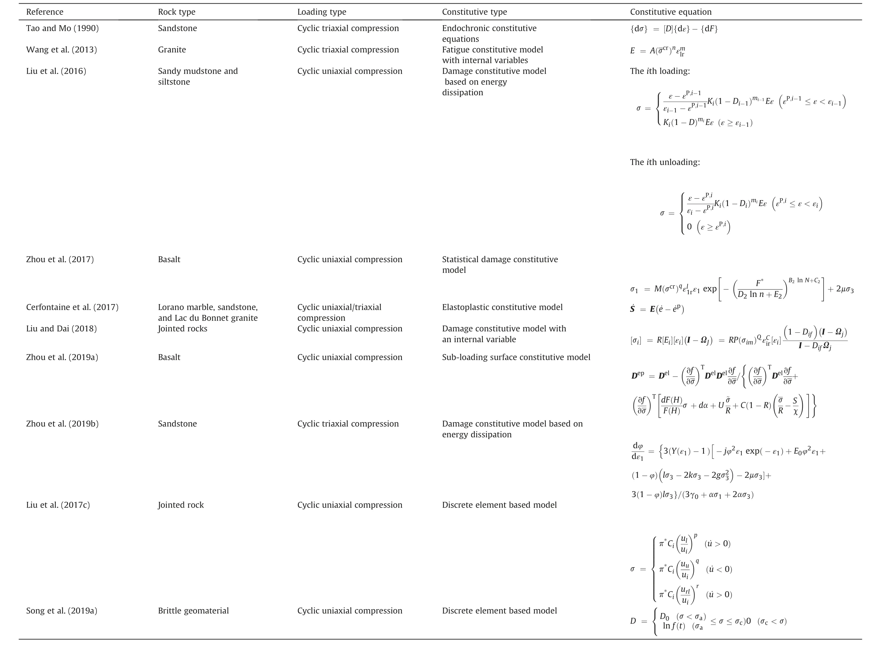
Table 3 Research timeline of constitutive relationship of rocks under cyclic loading conditions (1960-2020).
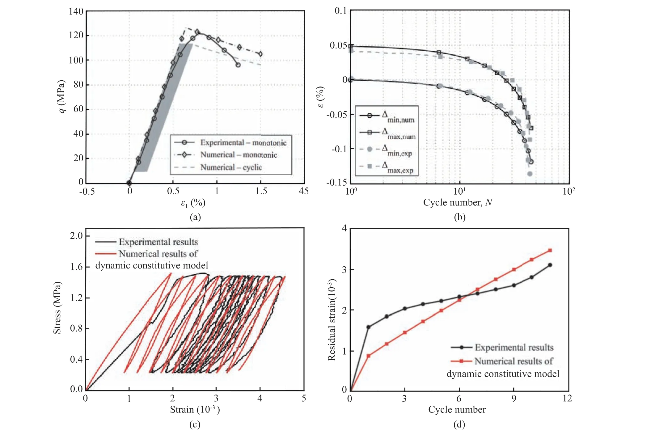
Fig. 23. Comparisons between theoretical and laboratory testing results of rocks under cyclic loads in terms of stress-strain curves and development of residual strain: (a)Elastoplastic constitutive model (data from Cerfontaine et al., 2017); and (b) Sub-loading surface model in terms of residual strain (data from Zhou et al., 2019a).
5. Discussion
According to previous literatures, the evolution of irreversible plastic strain, fatigue deformation modulus and accumulated damage variable of rocks subjected to cyclic loading can be divided into three phases,in which steady phase takes up most of the time of the whole cycle process. The reason why the steady stage keeps for a long cycling time may be interpreted from the micro-cracking mechanism of rocks. For instance, Chen et al.(2011) revealed the micro-crack development of granite under cyclic loads employing the fluorescent mean (Nishiyama and Kusuda,1996; Nishiyama et al., 2002), and the length and direction of micro-cracks were quantified by defining a parameter“crack population”; corresponding results are reproduced in Figs. 27 and 28. It can be observed that most of the newly developed cracks are short intra-granular cracks with length less than 0.2 mm in the initial and steady stages, which extend from the interfaces between different minerals and partly deviate from the loading direction. These cracks barely grow into macro-cracks,and thus the development of macroscopic behavior such as deformation and damage is steady without sharp variation.However,long cracks which could not be identified in steady stage are observed in the accelerated stage,and these cracks are beyond one grain and cut through several grain boundaries forming intergranular cracks with the preferential orientation of cracks parallel to loading direction.It is long inter-granular cracks that trigger the sudden fatigue fracture of rocks,and thus there is a sharp increase in macro-mechanical properties involving fatigue deformation and damage variable.
The reasons why the fatigue fracture of rocks under cyclic loading generally takes place more suddenly than the static failure under monotonic loading, and why there are more crushed rock fragments and wider crack bands in these cyclically failed rock specimens can also be interpreted from the micro-cracking mechanism of rocks.The length and orientation of cracks in failed rocks under monotonic compressive loading are depicted in Fig. 28f(Chen et al.,2011),in which the long inter-granular cracks observed in cyclically failed rocks are not identified, and the preferred orientation of cracks deviate from the loading direction.In addition,using the scanning electron microscope (SEM) imaging, Erarslan(2016) further confirmed that the inter-granular cracks causing grain debonding are the primary failure mechanism for rocks under cyclic loading. Fig. 29 depicts the SEM micrographs of surface of failed rocks subjected to monotonic and cyclic loading. Different from the monotonic loading cases,numerous small grains and dust were generated in the cyclically failed specimen.There are obvious intra-granular cracks along grain and cleavage cracks on the failure surfaces of rocks under monotonic loading,while the typical intergranular cracks around grains can be observed on the fracture surfaces of rocks under cyclic loading.
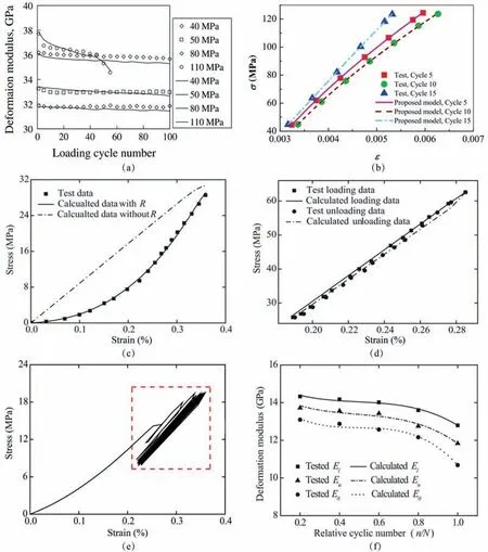
Fig.24. Comparisons of results obtained from laboratory tests and that calculated by internal variable model in terms of stress-strain curves and fatigue deformation moduli,data from (a) Wang et al. (2013), (b) Zhou et al. (2017), and (c-f) Liu and Dai (2018).
For fatigue constitutive relationship of rocks subjected to cyclic loading, although previous constitutive models mentioned in Section 4 are available for describing hysteresis loops and the accumulated deformation of rocks during the cycle process, there are still several aspects that can be improved:
(1) These models generally have too many material and model parameters, and the physical meaning of some model parameters is not clear. They are obtained simply by curve fitting.
(2) There are no explicit parameters controlling the size and shape of the hysteresis loop in these models, and the transitions of loading and unloading is not smooth enough.
(3) Some constitutive equations are derived based on laboratory tests,which are only applicable to a given loading condition,but not universal.Moreover,many influencing factors are not taken into account such as cyclic load waveform, loading parameters and water saturation.
(4) Existing fatigue constitutive models mainly concentrate on cyclic uniaxial/triaxial compression. The investigation of constitutive relationship for rocks under cyclic tensile or shear loading is rather limited.
These problems should be further investigated in future research to better apply the fatigue constitutive models in rock engineering practice.
6. Conclusions
In this study, literatures published over the last 60 years concerning on fatigue properties of rocks subjected to cyclic loads are reviewed. Representative results and main characteristics of deformation and failure mechanism and constitutive relationship of rocks are classified and illustrated in detail,and some ambiguous questions and prospective research are discussed. The following concluding remarks can be drawn.
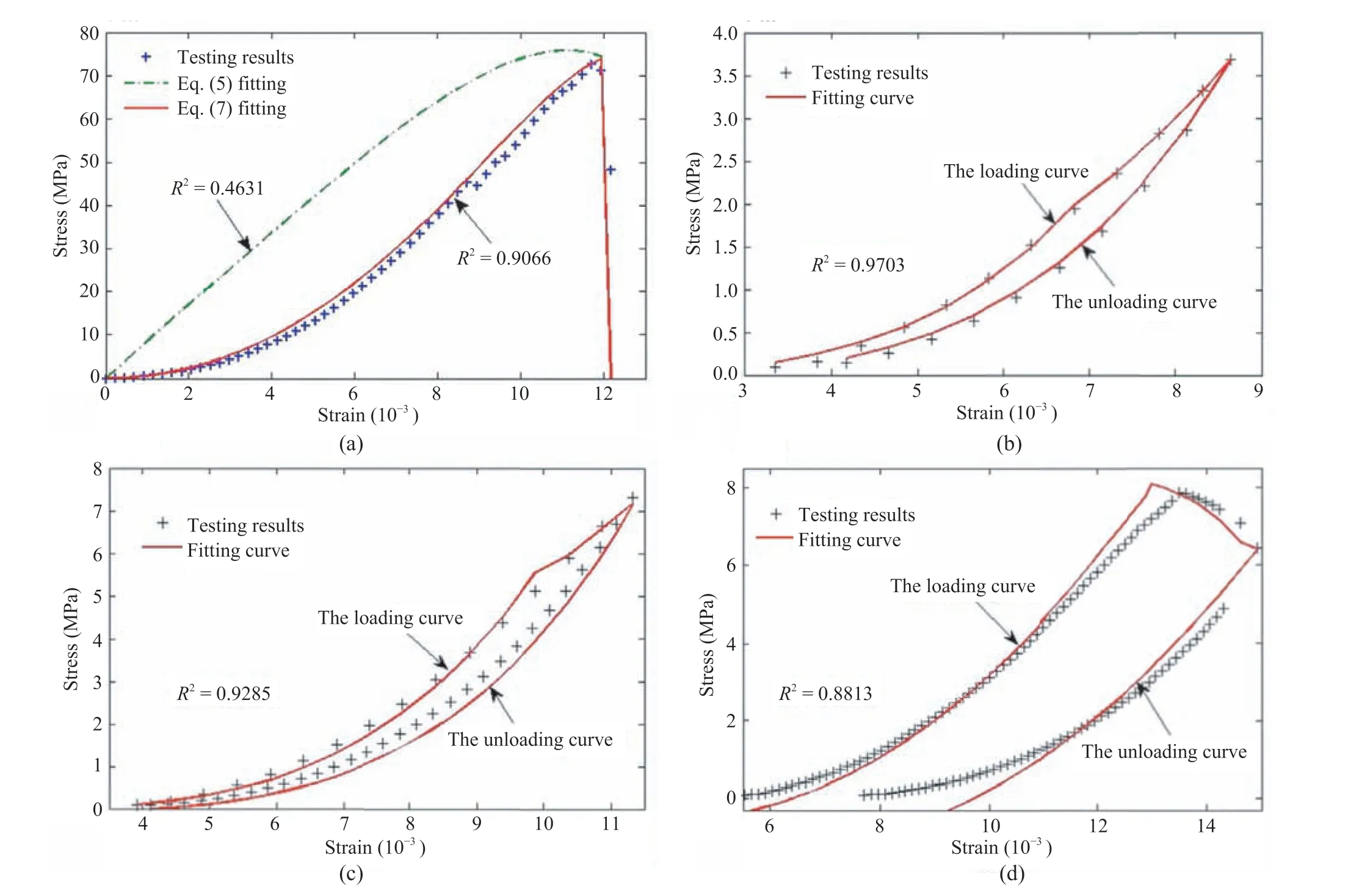
Fig. 25. Comparisons between theoretical and laboratory obtained stress-strain curves of rocks in distinct loading-unloading cycles (data from Liu et al., 2016).
For rocks under uniaxial cyclic compression,the terminal fatigue strain of rocks is approximately equal to the post-peak monotonic strain.However,such a fatigue failure law has not been observed for rocks under cyclic triaxial compression, cyclic tensile or shear loading. The evolution of irreversible plastic strain, fatigue deformation modulus, energy dissipation and damage variable of rocks under cyclic loads can be divided into three phases. In the initial stage, these mechanical properties vary rapidly, and then remain steady for a long cycling time until they vary again in the accelerated stage.Specially,the development of fatigue damage of rocks defined with different methods exhibits a similar inverted-S shape. Fatigue response of rocks is greatly affected by various factors.Under lower loading frequency or higher maximum stress and amplitude, rocks are generally featured by higher fatigue deformation moduli and higher dissipated hysteresis energy, leading to higher cumulative damage and lower fatigue life. Damage accumulates most quickly under square waveforms with higher cyclic energy requirement,while the damage induced by a ramp waveform is less.
Compared with monotonic loading cases, fatigue fracture of rocks subjected to cyclic loads usually occurs more suddenly, and there are more broken rock fragments and wider crack bands in cyclically failed rock specimens. Such phenomenon may be interpreted from the micro-cracking mechanism of rocks. From SEM imaging, it can be observed that numerous small grains and dust are generated in the cyclically failed specimen, but not under monotonic loading. Long inter-granular cracks beyond one grain and cutting through several grain boundaries can be observed on fracture surfaces of rocks subjected to cyclic loading, and preferentially oriented cracks are generally parallel to the loading direction.However,for rocks under monotonic loading,only short intragranular cracks along grain and cleavage cracks can be observed,and the preferred orientation of cracks deviate from the loading direction.
Several representative constitutive models for rocks under cyclic loading are compared, involving the elastoplastic model, the internal variable model, the energy-based damage model and the discrete element-based model. It can be observed that these models are effective to reproduce the nonlinear degradation of strength and stiffness, the hysteresis stress-strain curves and the accumulated plastic deformation. However, these models are still not widely used due to the multiple and complex material and model parameters. A fatigue constitutive model with explicit and simplified parameters should be further developed in future research that can be applied to rock engineering structures under various cyclic loading conditions.
Declaration of competing interest
The authors confirm that there are no known conflicts of interest associated with this publication, and there has been no significant financial support for this work that could have influenced its outcome.
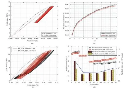
Fig.26. Comparisons between stress-strain curves obtained from laboratory tests and that simulated by the parallel-bonded stress corrosion(NPSC)model and a multi-level stress corrosion (MSC) model in terms of stress-strain curves (data from Song et al. 2019a,b). PFC: Particle flow code.
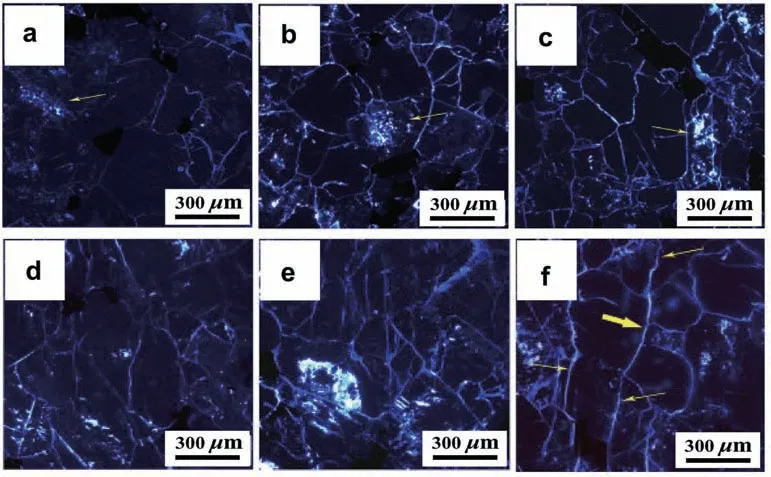
Fig. 27. Micro-crack development of granite during the whole cycle process (reproduced from Chen et al., 2011).
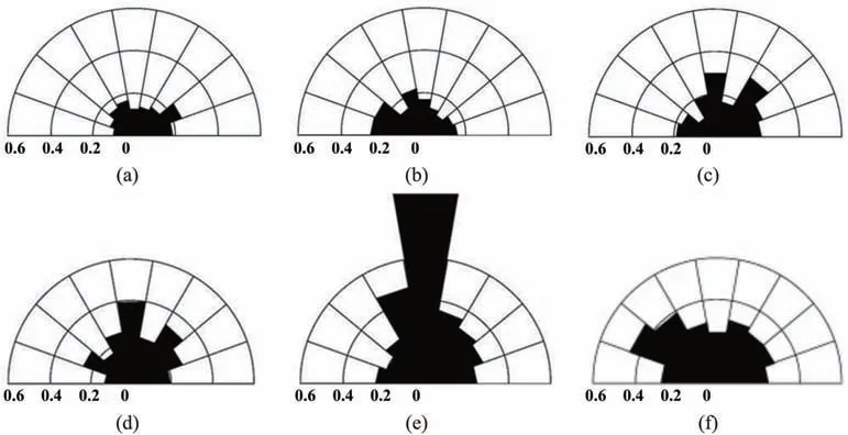
Fig. 28. The length and orientation of cracks in rocks during the cyclic loading and unloading process (reproduced from Chen et al., 2011).
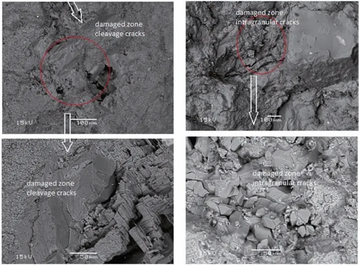
Fig. 29. SEM micrographs of fracture surfaces of failed rocks subjected to static (left) and cyclic (right) loads (reproduced from Erarslan, 2016).
Acknowledgements
The authors are grateful for the financial support from the National Natural Science Foundation of China (Grant Nos.52039007 and 52009086), and the Sichuan Province Youth Science and Technology Innovation Team, China (Grant No.2020JDTD0001).

 Journal of Rock Mechanics and Geotechnical Engineering2021年5期
- Journal of Rock Mechanics and Geotechnical Engineering的其它文章
- Surface characteristics analysis of fractures induced by supercritical CO2 and water through three-dimensional scanning and scanning electron micrography
- Prediction of fracture and dilatancy in granite using acoustic emission signal cloud
- Hysteresis in the ultrasonic parameters of saturated sandstone during freezing and thawing and correlations with unfrozen water content
- Coupled Eulerian-Lagrangian simulation of a modified direct shear apparatus for the measurement of residual shear strengths
- A novel true triaxial test system for microwave-induced fracturing of hard rocks
- Hydromechanical behavior of unsaturated expansive clay under repetitive loading
