A novel true triaxial test system for microwave-induced fracturing of hard rocks
Xia-Ting Feng, Jiuyu Zhang, Chengxiang Yang, Jun Tian, Feng Lin, Shiping Li, Xiangxin Su
Key Laboratory of Ministry of Education on Safe Mining of Deep Metal Mines, Northeastern University, Shenyang,110819, China
Keywords:Deep hard rock engineering True triaxial apparatus Microwave-induced fracturing of hard rocks Electromagnetic compatibility Dynamic monitoring Evolution of rock fracturing
ABSTRACT
1. Introduction
In excavation of deep hard rock engineering, the mechanical rock breakage often encounters the problems of an inability to cut,cutter wear(Liu and Liang,2000;Zheng et al.,2016)and rockburst induced by high in situ stress(Feng,2017).Mechanical breakage of hard rocks after microwave irradiation is considered as a promising technique for alleviating cutter wear (Santamarina,1989; Hassani,2010). Microwave as a high-frequency electromagnetic wave shows the advantages of selective heating, volumetric heating,rapid heating, and instantaneous control. Its irradiation has been proven to reduce the mechanical properties of hard rocks in laboratory experimental studies. The used microwave system can be divided into three subsystems depending on the type of microwave applicator: a resonant subsystem (e.g. single and multimode resonators), an open-ended subsystem (e.g. antennae and waveguide), and a traveling-wave subsystem(Makul et al., 2014).
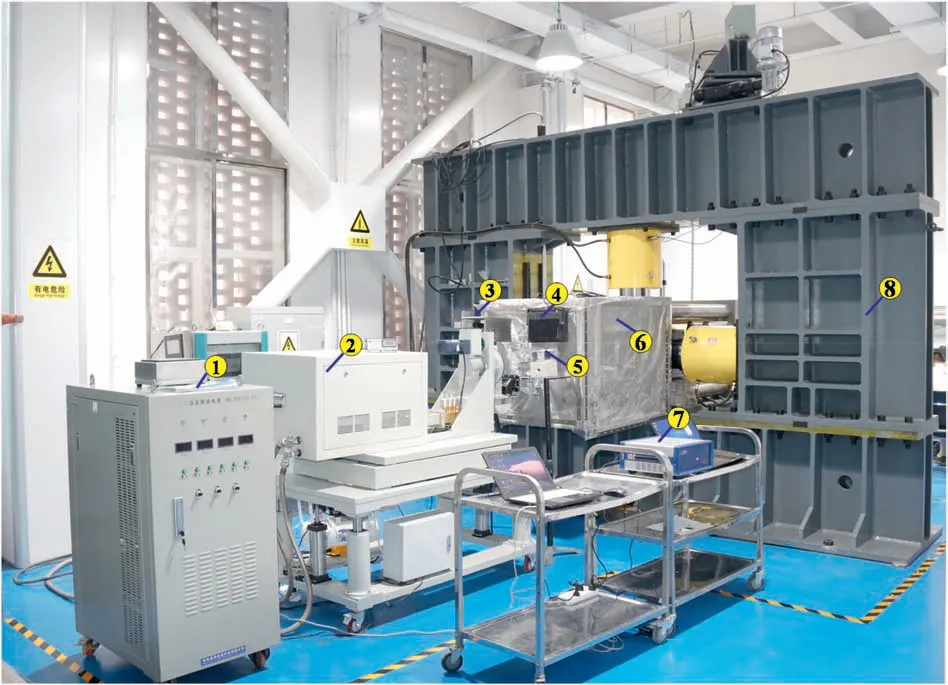
Fig.1. True triaxial system for microwave-induced fracturing of hard rocks.1 - High voltage supply; 2 - Microwave source; 3 - Thermal imager; 4 - Fill-in light; 5 - Industrial camera; 6 - Shield cavity; 7 - Demodulator; 8 - True triaxial apparatus.
In most studies, the responses of various hard rocks to microwave in resonant cavity system are revealed by conducting a series of physico-mechanical tests before and after microwave irradiation.These tests included point load tests(Satish et al.,2006),ultrasonic wave tests (Zheng et al., 2017; Hartlieb et al., 2018), tension tests(Hassani et al., 2016), uniaxial compression tests (Lu et al., 2019a),fracture toughness tests (Nekoovaght, 2015), scanning electron microscopy (SEM) tests (Nicco et al., 2020), and computed tomography(CT)tests(Li et al.,2020).However,the distribution and intensity of electric field in the resonant cavity were quite different from that of the open-ended type, which could yield different test results. Peinsitt et al. (2010) processed basalt, granite and sandstone samples in a microwave oven, and the results showed that their internal temperature was higher than that in the surface.This is quite different from that of the open-end type, where the temperature decreases exponentially with the depth of the rock(Hassani et al.,2016).In deep hard rock engineering,only the rock mass of the excavation face is directly exposed to microwave irradiation,and most of the microwave energy radiated will be directly dissipated in the air near the rock mass. Thus, an open-ended microwave system was supposed to be more suitable for field application (Mehdizadeh, 2015). Some researchers have tried to treat larger hard rock blocks using an open-ended system by comparing the physico-mechanical properties before and after microwave irradiation, including rock fracture characteristics and the distribution of thermal cracks (e.g. Koiwa et al., 1975), the ultrasonic wave velocity and uniaxial compressive strength at different positions(e.g.Takahashi et al.,1979),and the required cutting force(e.g.Hartlieb and Grafe, 2017). The characteristics and mechanisms of microwave-assisted mechanical rock breaking in microwave ovens and open-end microwave systems have been explored, however the thermal response and fracture evolution characteristics of hard rocks are not acquired during microwave irradiation.
More importantly,the effect of true triaxial stress on microwave weakening of hard rocks is neglected.Rock masses in underground hard rock engineering are in a state of true triaxial stress.Feng et al.(2016) developed a true triaxial testing apparatus to ascertain the deformation and strength of hard rocks under complex stress conditions.Lu et al.(2019b)conducted microwave-induced surface fracturing tests, and found that unidirectional stress changed the propagation and distribution of thermal cracks and fracture patterns.Therefore,the microwave-induced deformation and fracture of hard rocks are more complex under true triaxial stress.So far,the existing test apparatus and methods fail to satisfy the above requirements, therefore it is necessary to develop an apparatus for microwave-induced fracturing of hard rocks and monitoring technology under true triaxial stress.
The test system for microwave-induced fracturing of hard rocks under true triaxial stress was designed and manufactured at Northeastern University, China. The maximum output force of the true triaxial apparatus in the directions of three principal stresses is 5000 kN and the apparatus can accommodate specimens with the maximum dimensions of 400 mm × 400 mm × 400 mm. The test system can realize microwave-induced surface and borehole fracturing of hard rocks under the true triaxial high stress,and dynamic monitoring of the thermal response and rock fracture evolution during microwave loading.
2. Configuration of the test system
The test system (see Fig. 1) is an electromagnetic-thermalmechanical multi-field coupled test apparatus, which comprises a true triaxial stress loading system, an open-ended microwaveinduced fracturing system, a data acquisition system, an acoustic emission (AE) monitoring system, and an auxiliary specimen loading system. The test system can be used for investigating the behaviors of rock fracture induced by microwave under true triaxial stress, including microwave-induced surface fracturing for auxiliary mechanical rock breakage and borehole fracturing for destressing to reduce the risk of rockburst.
2.1. The true triaxial stress loading system
The true triaxial stress loading system consists of a rigid loading frame, triaxial stress loading subsystem, and the servocontrol subsystem (Fig. 2). In between the loading frames (in the x-direction), there is a rigid briquette allowed to move up and down freely, facilitating loading of large specimens and other components.
The rigid loading frame includes two horizontal frames, two vertical frames and one transverse frame,which produces reaction in the direction of three principal stresses. The transverse frame is composed of two loading plates and four rigid rods, and the front loading plate is connected to the shield cavity using gaskets.To meet the conditions of excavation face whereby five faces are compressed and one face is irradiated by microwave,the rock specimens have to be completely free from the front loading plate.Thus,the horizontal and vertical loading frames (in the x- and y-direction, respectively)can apply the major principal stress σ1,while the transverse frame(in the z-direction)can exert the other principal stresses provided that they are less than the sum of the frictional forces between the specimen and pressure plates in the other two directions (Fig. 2b)(see Section 4.2).In this case,the shear stress between the surface of the specimen and pressure plates will be generated.This‘‘end effect’’should be reduced in a conventional true triaxial apparatus. The object of the system is to simulate true triaxial conditions of the field and study rock fracture induced by microwave rather than mechanically-applied stress, and a certain shear stress on the rock surface is allowable(Su et al.,2017).
The triaxial stress loading subsystem includes a hydraulic station, three hydraulic cylinders, pressing plates, three pressure sensors,and three displacement sensors.The hydraulic station uses three hydraulic pumps with a working pressure of 70 MPa, which can generate 5000 kN in each of the three principal stress directions and produce a maximum stress of 125 MPa(σxand σy)on specimens measuring 200 mm × 200 mm × 200 mm. The displacement sensors are installed to monitor the movement of piston and rock specimen displacement. The pressure sensors are installed on the hydraulic cylinder barrel to monitor the oil pressure and the load of the rock. The testing machine can adapt to cubic rock specimens with a maximum size of 400 mm by adjusting the rigid pressure plates.To avoid mutual interference during true triaxial stress loading, there are two pressure plates of the same size as specimens(i.e.200 mm×200 mm and 400 mm×400 mm),and the other two are slightly smaller than specimens (i.e.190 mm × 190 mm and 390 mm × 390 mm), which results in the presence of loading gaps during true triaxial stress testing.
During loading, the specimens are placed at the geometric center of the pressure chamber.The three principal stresses can be controlled independently by the servo-control subsystem,including servo-motors, servo-controllers, and control software.Servo-controllers are used to process instructions from control software and feedback information from pressure and displacement sensors, and then adjust the speed of servo-motor. The loading system can be used for uniaxial, biaxial, and true triaxial tests under high in situ stress conditions.
2.2. The open-ended microwave-induced fracturing system of hard rocks
The radiation source in the test system is an open-ended microwave system with the maximum output power of 15 kW and a frequency of 2.45 GHz, which can be used for microwave-induced surface and borehole fracturing of hard rocks. The system can be divided into four subsystems: microwave generation subsystem,protection subsystem, transmission subsystem and rotation subsystem (Fig. 3). The microwave generation subsystem is used for converting alternating current into continuous high-frequency electromagnetic wave, including a magnetron, high-voltage power supply, and excitation cavity. The transmission subsystem is utilized to transmit high-frequency electromagnetic wave to the rock surface without any loss, including a rectangular waveguide,coaxial line, U-shaped waveguide, and microwave applicator. The protection subsystem is the key to the stable operation of the microwave system, and it includes cold-water circulation apparatus,circulator,coupler,tuner,power meter,and shield cavity.The coldwater circulation apparatus is adopted to decrease the magnetron temperature during microwave irradiation, avoiding thermal overload. The tuner is used for adjusting the impedance of the microwave system to match the rock load. The circulator is designed for isolating the microwave energy that has been reflected to the system. The rotation subsystem is used for simulating the microwave applicator rotating with tunnel boring machines(TBMs), including a motor, rotating joint and brackets.

Fig. 2. Schematic diagram of true triaxial stress loading system: (a) Three principal stress loading views; and (b) Sectional view of A-A.1 - Front loading plate; 2 - Forklift; 3 -Loading route; 4 - Unloading route; 5 - Loading jack; 6 - Movable briquette; 7 - Rock specimen; 8 - Pressure plates; 9 - Friction.
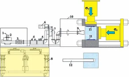
Fig.3. The open-ended microwave-induced fracturing system of hard rocks.1-Cold-water cycle;2-Magnetron;3-Circulator;4-Coupler;5-Tuner;6-Electric motor;7-Rotating joint; 8 - Lifting platform; 9 - Pyramid horn applicator; 10 - Shield cavity; 11 - Friction; 12 - Coaxial applicator.
According to the application of auxiliary mechanical rock breakage and rockburst prevention, there are two types of microwave applicators designed for fracturing of hard rocks, i.e.microwave-induced surface and borehole fracturing applicators. A waveguide is regarded as the simplest surface applicator, while it shows the disadvantages of small aperture,weak directionality,and poor matching with free space. An E-plane horn (open surface:109 mm×109 mm)applicator and a horn applicator(open surface:200 mm×200 mm)are designed by gradually enlarging the open surface of rectangular waveguide,which can improve the matching with free space and increase the power density applied to the rock surface. A circular applicator with high power for long-distance lossless transmission should be selected when conducting microwave-induced borehole fracturing test. Compared with a circular waveguide applicator,the coaxial type is not limited by cutoff wavelength, and can be used for different sizes of boreholes,thus hard coaxial type with diameters of 48 mm and 75 mm and soft coaxial type with diameters of 40 mm are made for microwaveinduced borehole fracturing.
Body tissue, when directly exposed to microwave radiation,suffers thermal and biological effects.Biological effects refer to the fact that microwave energy can change the living environment and physiological activities of organisms (Michaelson, 1980).Suppressing microwave leakage is essential for the safe operation of such microwave system. The shield cavity, measuring 860 mm × 860 mm × 1200 mm, was designed to confine the electromagnetic wave within a limited space, therefore, the microwave intensity of leakage is lower than the requirements of electromagnetic radiation protection specifications (leakage microwave power density < 5 mW/cm2) (IRPA, 1998; GB 5959.6-2008, 2008).
2.3. The auxiliary specimen loading system
The specimen loading system is specially used for loading and unloading large-size specimens and other loading components,including a mobile jib crane,loading platform,telescopic hydraulic jack and forklift.The mobile jib crane with the maximum capacity of 1000 kg is used for lifting specimens, including the rotary drive motor,electric hoist,and cantilever.There is a telescopic hydraulic jack with the maximum working stroke of 750 mm installed in the loading platform and vertical loading frame, respectively, which can be used for moving the specimens to the triaxial pressure chamber. The loading and unloading routes are demonstrated in Fig. 2b.
2.4. The data acquisition system
The data acquisition system is mainly composed of an infrared thermal imager, demodulator, optical fiber, charge coupled device (CCD) industrial camera, computer, pressure and displacement sensors, and data acquisition software (Fig. 4). The infrared thermal imager is employed to monitor the surface temperature of rock, and the maximum temperature is measured 2000°C with an accuracy of ±0.01°C. The demodulator and distributed optical fiber are used to monitor the temperature in rock borehole,and the maximum temperature is measured 400°C with an accuracy of ±0.1°C. The industrial camera is used to record the characteristics of rock fracture during the test, and then the deformation of the rock surface irradiated is investigated by twodimensional(2D)digital speckle technique.During the loading of true triaxial stress and microwave, the collected data are respectively transmitted to the control software for display and storage, realizing automatic acquisition of test data. In this way,an unmonitored test is possible when high-power microwave is applied.
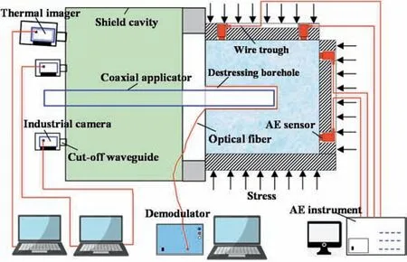
Fig. 4. Diagram of the data acquisition system.
2.5. The AE monitoring system
To study the thermal damage evolution and fracture process during microwave irradiation, a PCI2-Main-34 AE system developed by Physical Acoustics Corporation is used.Twelve AE sensors are installed in the pressure plates with holes and wire troughs and fixed directly onto the surface of the rock using springs under high pressure. Vaseline is smeared between the AE sensors and the surface of the specimens to ensure good contact.
3. Key issues in the developed system
3.1. The coupling loading of true triaxial stress and microwave irradiation
Microwave heating of hard rocks may involve the risk of exposure of personnel to microwave energy and interfere with other electronic equipment in the laboratory if precautions are not taken.To realize the coupling loading of microwave and true triaxial stress,it is necessary to reduce the electromagnetic leakage below the safety threshold.In microwave-induced fracturing by an openended type of microwave system, most of the microwave energy radiated will be dissipated in the air around the rock mass. There are many gaps on the surface of the rock and between the pressure plates, allowing the leakage of electromagnetic wave energy.Additionally,pressure plates can move with the three oil cylinders during three-dimensional (3D) stress loading. In the industrial microwave heating equipment, the box made of metal plate or metal mesh is used to prevent microwave from spreading outward.The local leakage is suppressed by the sealing door, choking apparatus, cut-off waveguide and absorbing material (Decareau,1985); but for equipment comprising complex shapes or discontinuous structures, microwave leakage still occurs, and the sensor will be subjected to interference when installed in a strong microwave field.
According to the above analysis, rock specimens should be isolated from the strong microwave field. Based on the irradiation surface,electromagnetic shielding of the test system can be divided into the front-and back-end shielding(Fig.5).A closed metal cavity is designed for front-end shielding, which is composed of four aluminum frames, wire mesh, a front-loading plate, and gaskets.The wire mesh is fixed on the aluminum frame and front-loading plate. To ensure the effectiveness of the shielding cavity, gaskets are used between metal mesh and frames to eliminate non-contact points. Most of the microwave energy will be confined within the shield cavity,which is helpful when monitoring the process of rock fracturing during microwave irradiation.
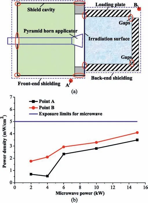
Fig. 5. (a) Schematic diagram of electromagnetic shielding during loading of true triaxial stress and microwave;and(b)Power density of microwave leakage at different powers.
The back-end shielding is mainly used to avoid microwave leakage from both the rock specimens and pressure plates. The microwave has such propagation characteristics that there is no obvious leakage when the length of the gaps is far less than the wavelength. The contact surface between the front-loading plate and the rock is connected by aluminum foil tape forming a whole with the front shield, which is the key position of the back-end shielding. The gaps on the rock surface are sealed by aluminum foil tape, soft metal mesh and magnetic components. Besides,slightly larger notches between loading plates must be filled by soft metal mesh, and then sealed by aluminum foil tape. By this, the leaked microwave is suppressed to below the safe threshold(Fig.5b).In Fig.5a,A and B are electromagnetic leakage monitoring points,which are respectively 600 mm away from the shield cavity and rock specimen, while the test console is further away still.
3.2. Dynamic monitoring of thermal response and fracture evolution for hard rocks
The thermal response and characteristics of fracture evolution are essential to understand the mechanism of microwave-induced fracturing of hard rocks under true triaxial stress. High-intensity microwave irradiation can produce induced current in electronic equipment, causing breakdown or burning of electronic components and distortion of sensor output signals.Therefore,traditional electrical sensors cannot monitor the response characteristics of rock during microwave heating. The sensors with metal shielding layer may suppress the interference of microwave and output the measured data in a stable manner. Chen et al. (2020)explored the heating characteristics of concrete under microwave irradiation using a shielded thermocouple. However, the drawback thereof is that it can only monitor the temperature at one point in the rock.Gao et al.(2020)measured the surface temperature of granite after microwave irradiation by thermal imager but not during microwave irradiation.
By means of a non-contact, non-electrical monitoring method,and cut-off waveguide, a dynamic monitoring system of thermal response and fracture evolution of hard rocks during microwave irradiation is developed, including an infrared thermometry technique, distributed optic fiber sensing technique, AE monitoring technique,and 2D digital speckle correlation technique.The cut-off waveguide does not allow electromagnetic wave below the cut-off frequency to pass through, which can be designed to shield test equipment according to the frequency of interference signals(Stutzman and Thiele,1998).From the perspective of the principle of thermal imager and camera,the acquisition of temperature and image can be completely unaffected by electromagnetic field. The following methods can be adopted. The monitoring equipment is installed outside the shield cavity for isolating the microwave field.Closed metal boxes are employed to reduce the impact of leaked microwave energy on equipment. The cut-off waveguide is respectively connected with the metal box and the shield cavity,which is utilized to observe the surface temperature and failure process of rock.

Fig. 6. The rock surface temperature monitored by two monitoring methods: (a)Temperature field on the rock surface by thermal imager; and (b) The accuracy of surface temperature monitored by distributed optical fiber compared with thermal imager.
The temperature in rock borehole is monitored by the distributed optical fiber,which shows the characteristics of small volume,low cost, flexibility, and a larger monitoring range. The greatest advantage of the optical fiber is that it is completely unaffected by electromagnetic field even in close contact with the rock surface.The thermal imager and distributed optical fibers are used to monitor the rock surface temperature simultaneously, comparing their feasibility and accuracy.Fig.6 displays the temperature of rock surface monitored by the thermal imager and distributed optical fiber at σ1=20 MPa, σ2=10 MPa,σ3= 5 MPa, microwave power P=2 kW,and irradiation time t=20 min.A and B are the start and end points of the distributed optical fiber.It can be seen from Fig.6 that both methods allow stable measurement of the surface temperature of the rock in a strong microwave field,indicating that the shielding methods used has suppressed the interference caused by strong electromagnetic wave. Compared with thermal imager, the average error of temperature measured by the distributed optical fiber is smaller than 5°C,with no anomalous values being recorded throughout the experiment.This shows that the distributed optical fiber can be used for dynamic monitoring of rock surface and borehole temperature under the strong microwave field.

Fig.7. (a)AE activity during microwave irradiation under strong electromagnetic field;and (b) The AE waveform at point A.
The fracture evolution and mechanism of rock can be ascertained by AE activities. In the past, the acquisition of AE data was affected by noise signals, such as mechanical and electromagnetic noises.It is difficult to monitor the evolution of rock fracture by AE technique under strong electromagnetic field and hightemperature conditions. This section will introduce the apparatus and method used to characterize the microwave-induced fracturing of hard rocks under true triaxial stress.The AE sensor is selfdeveloped and packaged with aluminum alloy shell for isolating electromagnetic wave around the rock surface, and its bottom is connected to the waveguide rod which can withstand a temperature of 400°C. The rigid plate is designed with holes and wire troughs.The Polytetrafluoroethylene(PTFE)gaskets and AE sensors are placed in the hole and the wire trough does not contact the rock specimen. In addition, the equipment used in the test should be connected to the earth wire.At σ1=σ2=σ3=5 MPa,P=3 kW,and t=10 min,the AE signal and waveform are collected under strong microwave irradiation(Fig.7).AE sensors can stably record the rock fracture process, and the AE waveform is also similar to that in conventional tests (Katsuyama,1996; Wang et al., 2020), implying that the existing shielding methods can suppress the influences of strong electromagnetic field on AE acquisition.
4. Experimental methods
4.1. Preparation of specimens
The test system could realize microwave-induced surface and borehole fracturing of hard rocks under true triaxial stress.Microwave-induced surface fracturing was used to assist mechanical breaking of hard rocks (e.g. when using a TBM) in mining and civil engineering applications. Microwave-induced borehole fracturing was used to release and transfer energy accumulated in deep hard rock strata to reduce the risk of rockburst.There are two types of rock specimens: complete specimens and specimens with a borehole,whose methods of preparation are similar. The preparation of specimens with a borehole is described as follows.A large rock block was cut into cubes measuring 202 mm×202 mm×202 mm and a hole was then drilled through the center of each specimen.The rock block was then ground into smooth specimens measuring 200 mm × 200 mm × 200 mm. After preparation, the specimens were then air-dried naturally in the laboratory for at least 7 d. In addition,according to the wave velocity of specimens,the anisotropy could be pre-judged to select those specimens with good homogeneity.
4.2. Microwave-induced surface fracturing experiment under true triaxial stress
The test mainly includes electromagnetic shielding,true triaxial stress loading,microwave loading,and dynamic monitoring.Before each test,it is necessary to apply electromagnetic shielding for the gaps and equipment. The electromagnetic leakage must be monitored in real time during the test. Furthermore, the surface applicator needs to be moved to the center of the rock.During loading of true triaxial stress,the time,rate,and magnitude of the z-direction stress (free surface) loading depend on the sum of the frictional forces in the directions of the other two principal stresses. When the friction coefficient of the other two principal stresses is greater than 0.5, three principal stresses can be loaded simultaneously at the same rate. However, the z-direction stress must be unloaded before the other two principal stresses. Microwave energy is applied after true triaxial stress loading is completed. First, the cold-water circulation apparatus must be started for ensuring sufficient water during the test.Then,the magnetron is preheated for at least 5 min, and the reflected power is adjusted to less than 0.05 kW using a tuner when the input power is 2 kW. Finally, the microwave power and time are set to heat the rock till fracture under true triaxial stress.
4.3. Microwave-induced borehole fracturing experiment under true triaxial stress
The process of microwave-induced borehole fracturing experiment is as outlined in Section 4.2, including electromagnetic shielding, true triaxial stress loading, microwave loading, and dynamic monitoring. Some differences include the facts that the coaxial applicator is used in the tests, which needs to be placed in a destressing borehole. After the loading of the three principal stresses is completed,the camera is used to record the rock fracture in the borehole, and then the applicator is moved slowly into the borehole by a certain distance. The temperature in the borehole is measured by the distributed optical fiber, which is fixed along the borehole wall and bottom edge using a high-temperature tape.
5. Results and analysis
5.1. Experimental program
Basalt specimens,which are typical microwave-sensitive,hard,and brittle rocks in the test,were sampled from Chifeng City,Inner Mongolia, China. Intact specimens with the size of 200 mm×200 mm×200 mm are used in the microwave-induced surface fracturing tests. The borehole specimens with the size of 200 mm×200 mm×200 mm are used in the microwave-induced borehole fracturing test, and the borehole has a diameter of 55 mm and depth of 100 mm. Before the test, the wave velocity and mass of the specimens are measured. The wave velocity at room temperature is about 5677 m/s, the average density is 2900 kg/m3, and the average uniaxial compressive strength is 285 MPa. During microwave irradiation, the three principal stresses remain constant. The microwave-induced surface and borehole fracturing experimental programs are displayed in Table 1.In the microwave-induced borehole fracturing test,σxand σyare perpendicular to the borehole axis, and σzis parallel to the borehole axis. In the microwave-induced surface fracturing tests,the basalt specimens I and II are heated by microwave for 5 min and 15 min, respectively.
5.2. Experimental results for microwave-induced surface fracturing of hard rocks
AE activity can reflect the generation, expansion, and penetration of thermal cracks in the rock under the coupled action of stress and temperature fields, and its sudden change directly shows the different stages of the development of cracks in the rock(Katsuyama,1996).Fig.8 illustrates the temperature and AE activity under test conditions.Fig.8b and d demonstrates the data recorded during microwave irradiation.The heating rate of two specimens is gradually reduced because the rate of heat dissipation to the surrounding air is positively related to temperature. During the loading of three principal stresses,a small amount of AE activity is generated,and almost negligible when the three principal stresses are constant. During the test, there is some local flaky spalling in Specimen I,which leads to a significant difference in the AE counts between the two specimens. Without macrocracks observed to penetrate the entire specimens, only a few tensile cracks are generated on the rock surface,showing a slightly closed state.There is a significant difference between the initiation, propagation, and distribution of thermal cracks under unstressed conditions (Lu et al., 2019b), indicating that the 3D stress inhibits the development of thermal cracks and extent of fracturing. In addition, there are marked heating traces in the center of the specimen.Specimen II, after microwave-induced surface fracturing, is shown in Fig. 9.

Table 1 Experimental programs of microwave-induced surface and borehole fracturing of basalt.
According to Specimen I, thermal fracture evolution and key characteristic temperature were investigated during the application of true triaxial stress and microwave irradiation. AE activities show intermittent characteristics (calm-active-calm), which can be divided into a silent period with no AE activity, a quiet period with some AE activity,and an active period with a great amount of continuous AE activity. At 0-100 s, there are a few AE events, and the rock remains at its thermoelastic stage and almost no elastic strain energy is released.From 100 s to 156 s,continuous AE activity begins to appear,indicating that the rock is at the plastic yield stage and new microcracks are continuously produced. From 212 s to 300 s,the AE activity shows a rapid step-jump increase,indicating that macrocracks expand and penetrate rapidly. At 61 s, the AE signal begins to appear corresponding to the temperature of 141.1°C. At 156 s, the AE activity exhibits an instantaneous linear jump for the first time, indicating that the microcracks in the rock merge without macrocracks occurring, corresponding to a temperature of 257.2°C. At 212 s, the AE activity begins to increase rapidly, indicating that macrocracks begin to appear in the rock,corresponding to a temperature of 309.3°C.
During the microwave loading of Specimen II,the cumulative AE counts in the first 300 s account for about 70%of that in the entire test, while that after 600 s is only 30% thereof, showing that thermal cracking is mainly produced at 0-300 s. This is because the rock has been fractured several times and the rate of heating is gradually reduced, resulting in the subsequent accumulation of energy that is insufficient to support the continued growth of the original cracks and the generation of new cracks.Comparing basalt specimens I and II, it is found that AE activity begins to appear at about 60 s, and continues at about 220 s, indicating that the generation of thermal fracture requires a long incubation time.
5.3. Experimental results for microwave-induced borehole fracturing of hard rocks
Fig.10 shows the surface temperature distribution characteristics in the borehole during microwave-induced borehole fracturing of basalt.The microwave irradiation port is about 50 mm from the borehole bottom, and the optical fiber is fixed along both sides of the borehole wall and bottom edge. D and E are the start and end points of the monitoring range, respectively (Fig. 10a). The temperature distribution in the borehole presents a hump-like shape:on both sides of the borehole wall, it first increases and then gradually decreases, while the temperature at the bottom is lower and more uniform. The distance between the peak points on both sides and the borehole bottom is about 40 mm.The temperature is related to the electric field distribution and intensity in the borehole. The microwave propagates to the direction of borehole bottom and the opening,respectively.The closer it is to the irradiation port, the higher the corresponding temperature. Therefore,reducing the distance to the borehole bottom can improve the rate of utilization of microwave energy.In addition,the temperature at points A,B,and C increases approximately linearly with irradiation time.
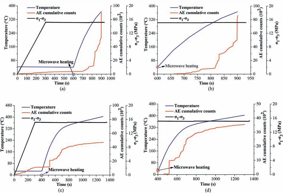
Fig. 8. Temperature and AE activity during microwave-induced surface fracturing of basalt: (a) at P = 6 kW and t = 5 min and (b) partially magnified views of (a); and (c) at P = 6 kW and t = 15 min and (d) partially magnified views of (c).

Fig. 9. Specimen II of basalt after microwave-induced surface fracturing.
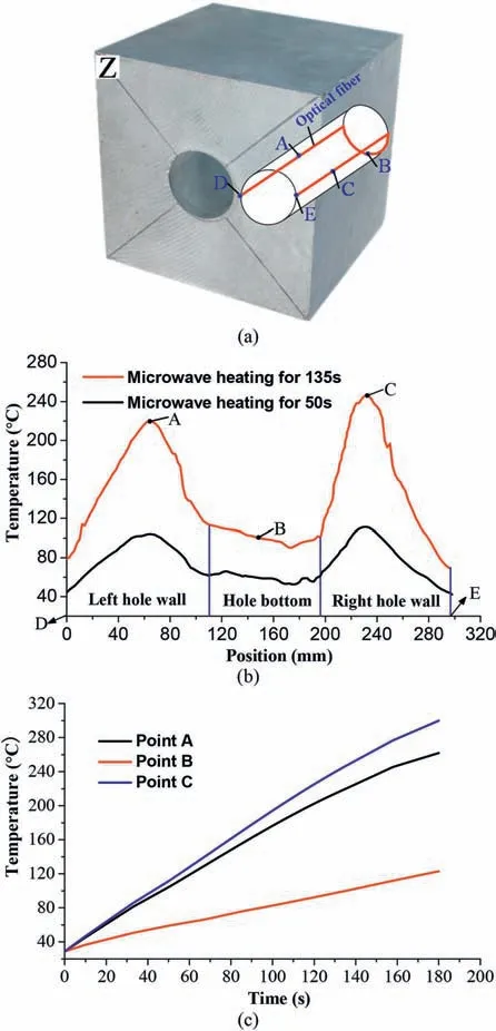
Fig. 10. Temperature distribution in the borehole monitored by distributed optical fiber: (a) Optical fiber fixed in the borehole; (b) Temperature distribution in the borehole at 50 s and 135 s; and (c) Heating characteristics at points A, B and C.
Fig.11 demonstrates the temperature and AE activity under true triaxial stress and microwave irradiation.Under true triaxial stress loading and remaining constant,there is only a small amount of AE activity,indicating that most of the energy in the process of loading is transformed into elastic strain energy in the rock.At 180 s,the AE activity has a sharp increase indicating that many macrocracks are rapidly produced in the rock.Then a violent brittle fracture occurs with the release of a large amount of elastic strain energy.After the test, there are multiple connected macrocracks observed on each surface of the specimen.Four vertical tensile cracks extending into the borehole are generated near the borehole. At the same time,there is a ring syncline crack on the borehole wall, and no macrocracks appear at the bottom of the borehole (Fig. 12). Compared with the results of microwave-induced borehole fracturing under unstressed conditions (Lu et al., 2019b), 3D stress promotes the distribution of thermal cracks in rocks, but inhibits the width of cracks.
The generation and propagation of cracks will dissipate a large amount of elastic strain energy and cause stress relaxation in the rock, which is critical to destressing in a deep rock mass by microwave-induced borehole fracturing. According to the AE activity during the loading of true triaxial stress and microwave, the thermal cracking evolution and the key characteristic temperature were also investigated. At 0-104 s, there is a small amount of AE activity, suggesting that the rock is still at the thermoelastic stage without release of strain energy. At 104-180 s, there are many continuous AE events, indicating that microcracks generate in the rock and converge into macrocracks, then expand and are connected rapidly. At 29 s, the AE signal begins to appear corresponding to a temperature of 50°C at point C. At 116 s, the AE activity shows an instantaneous linear increase for the first time,and the cumulative count jumps from 1428 to 6851,indicating that the microcracks in the rock merge and macrocracks appear at this time(the corresponding temperature at point C is 189.7°C).The AE activity begins to show a continuous and rapid increase at 142 s,indicating that the macrocracks in the rock propagate rapidly and continuously produce new cracks (the temperature at point C was 226.6°C). The cumulative AE event counts before 116 s are only 1418, implying that most of the thermal cracks are generated between 116 s and 180 s. AE activity can identify the characteristic time of different stages of rock fracture during microwave irradiation, which is of great significance for optimization of the parameters related to microwave-induced borehole fracturing in the deep hard rock engineering.
6. Conclusions
To reveal the mechanism of microwave-induced fracturing under true triaxial stress, we developed a novel true triaxial test system for microwave-induced fracturing of hard rocks.This study introduces the advantages of the test system, its configuration,solving key issues, and corresponding test methods. Moreover,microwave-induced surface and borehole fracturing tests were conducted under true triaxial stress to validate the reliability of the test system. The following conclusions can be drawn:
(1) The microwave-induced surface and borehole fracturing tests under true triaxial stress were realized for the first time,which overcomes the problem of electromagnetic leakage in the coupling loading of true triaxial stress and microwave.
(2) By developing a dynamic monitoring system, the thermal response and fracture evolution were obtained when microwave-induced fracturing of hard rocks was realized under true triaxial stress.

Fig.11. Temperature and AE activity during microwave-induced borehole fracturing of basalt: (a) at P = 6 kW and t = 3 min; and (b) Partially magnified view of (a).

Fig.12. Basalt specimen after microwave-induced borehole fracturing at P=6 kW and t = 3 min.
(3) The results showed that the thermal cracking presents the intermittent characteristics(i.e.calm-active-calm)during microwave-induced fracturing of basalt.In addition,The true triaxial stress can inhibit the development and distribution of thermal cracks during microwave-induced surface fracturing. When microwave-induced borehole fracturing occurs, it promotes the distribution of thermal cracks in rock,but inhibits the width of cracks.(4) The reliability of the test system was verified by applying a series of tests. The development of the system provides a method for investigating microwave-assisted rock breakage technique under true triaxial stress.
Declaration of competing interest
The authors declare that they have no known competing financial interests or personal relationships that could have appeared to influence the work reported in this paper.
Acknowledgments
The authors acknowledge the financial support from the National Natural Science Foundation of China (Grant No. 41827806)and the Liaoning Revitalization Talent Program (Grant No.XLYC1801002). The authors thank Dr. Gaoming Lu and Mr. Hanxu Zhao for their valuable help during the development of the test system.The authors also acknowledge Ms.Yuying You for her help in improving the English.
 Journal of Rock Mechanics and Geotechnical Engineering2021年5期
- Journal of Rock Mechanics and Geotechnical Engineering的其它文章
- Surface characteristics analysis of fractures induced by supercritical CO2 and water through three-dimensional scanning and scanning electron micrography
- Prediction of fracture and dilatancy in granite using acoustic emission signal cloud
- Hysteresis in the ultrasonic parameters of saturated sandstone during freezing and thawing and correlations with unfrozen water content
- Coupled Eulerian-Lagrangian simulation of a modified direct shear apparatus for the measurement of residual shear strengths
- Hydromechanical behavior of unsaturated expansive clay under repetitive loading
- Laboratory large-scale pullout investigation of a new reinforcement of composite geosynthetic strip
