Consolidation of soft clay foundation improved by geosyntheticreinforced granular columns: Numerical evaluation
Nima R. Alkhorshid, Gregório L.S. Araujo, Ennio M. Palmeira
a Institute of Integrated Engineering, Federal University of Itajubá - Itabira Campus, Itabira, Minas Gerais, 35903-087, Brazil
b Department of Civil and Environmental Engineering, University of Brasília, Brasília, Distrito Federal, 70910-900, Brazil
Keywords:Geosynthetic Embankment Granular column Consolidation Soft soil
ABSTRACT Soft clays are problematic soils as they present high compressibility and low shear strength. There are several methods for improving in situ conditions of soft clays. Based on the geotechnical problem’s geometry and characteristics,the in situ conditions may require reinforcement to restrain instability and construction settlements. Granular columns reinforced by geosynthetic material are widely used to reduce settlements of embankments on soft clays.They also accelerate the consolidation rate by reducing the drainage path’s length and increasing the foundation soil’s bearing capacity. In this study, the performance of encased and layered granular columns in soft clay is investigated and discussed. The numerical results show the significance of geosynthetic stiffness and the column length on the embankment settlements. Furthermore, the results show that granular columns may play an important role in dissipating the excess pore water pressures and accelerating the consolidation settlements of embankments on soft clays.
1. Introduction
Granular columns are widely used in geotechnical engineering to reduce settlement, increase bearing capacity, accelerate consolidation, and decrease liquefaction potential. Based on the surrounding soil’s lateral confinement,the required granular columns’strength and stiffness may be determined(Zhang et al.,2013).Due to low shear strength presented by very soft soils,granular columns in such soils are not suggested. This issue can be solved by lateral support of the column material using geosynthetic encasement.In the recent past, geotextile has been used for encasing granular columns in very soft soils.Geotextile provides confinement around the columns and behaves as drainage and filter boundary,yielding less contamination of the sand core with soft soil particles (Castro and Sagaseta, 2011; Zhang et al., 2012; Pulko and Logar, 2017;Chen et al.,2020;Li et al.,2020).Geogrid may be a stiffer alternative to geotextile (Araujo et al., 2009; Gniel and Bouazza, 2009;Murugesan and Rajagopal,2010;Gu et al.,2016),but it cannot avoid the sand core contamination.
Recently, various field and laboratory works have been carried out to evaluate geosynthetic-encased granular column’s performance(De Mello et al.,2008;Alexiew and Raithel,2015;Xue et al.,2019; Chen et al., 2020). The granular column’s application has experienced different designs such as partial and full encasement(Ali et al., 2012; Yoo and Lee, 2012; Alkhorshid, 2017; Alkhorshid et al., 2020; Cengiz and Guler, 2020; Zhang et al., 2020), floating conventional and encased columns (Ali et al., 2014; Rathod et al.,2020), and a few laboratory tests on geosynthetic-layered columns (Sharma et al., 2004) which are non-encased columns reinforced by geosynthetic disks within their inner region.
Finite element method (FEM) has been extensively used to evaluate the behavior of encased granular columns (Khabbazian et al., 2010; Alkhorshid, 2012; Alkhorshid et al., 2014;Keykhosropur et al., 2012; Castro and Sagaseta, 2013; Mohapatra et al., 2017; Nagula et al., 2018; Hosseinpour et al., 2019). However, encased granular columns are considered as a new method for supporting embankments and need to be investigated to understand their behavior and to improve design methods. In this numerical study, finite element analyses have been carried out using PLAXIS 2D to study the influence of granular column design approach on its performance. Besides partially encased, fully encased end-bearing, and floating columns, a new approach was taken to reinforce the granular column. In this approach, the column is partly encased and partly layered with geosynthetic.
2. Modeling with PLAXIS 2D
2.1. Proposed model
The displacement method is commonly used as the installation method of granular columns in very soft soils(Alexiew et al.,2005;Gniel and Bouazza, 2009). It is carried out either by a static or jointly by a static and dynamic installation that causes cylindrical soil densification (Fig.1) around the column (smear zone), which changes the value of the coefficient of lateral earth pressure(K).As reported by Priebe(1995)and Gäb et al.(2008),this coefficient can be assumed as K = 1, and Goughnour and Bayuk (1979) took this coefficient as K0< K < Kp, where K0and Kpare the coefficients of earth pressure at rest and the passive earth pressure of the soil,respectively.Walker and Indraratna(2006)stated that the radius of the smear zone (rs) could be estimated as 2-3 times the radius of the column (rc). Weber (2008) assumed rsas twice rc, and Wang(2009) assumed rsto be 1-2 times rcand ks/khequals 0.1, where ksand khare the coefficient of permeability of the smear zone and horizontal coefficient of permeability of the soil, respectively.Alkhorshid (2017) and Alkhorshid et al. (2019) carried out a series of large-scale laboratory tests and measured the smear zone’s radius as 1.8-1.9 times the column diameter.The unit cell concept(Fig.1) was adopted to represent a cylindrical column-soil system with a radius equal to the radius of the column influence zone(re).Several researchers have used the unit cell concept to evaluate soft soil reinforcement with encased columns (e.g. Murugesan and Rajagopal, 2007; Almeida et al., 2013; Rajesh, 2017; Gholaminejad et al., 2020).
2.2. Hardening soil (HS) model
Hardening soil (HS) model is a development on the Mohr-Coulomb (MC) model that associates the nonlinear elastic model to the elastoplastic model.This model can simulate the behavior of both soft and stiff soils. More information on this model is presented in Schanz(1998) and Schanz et al. (1999).
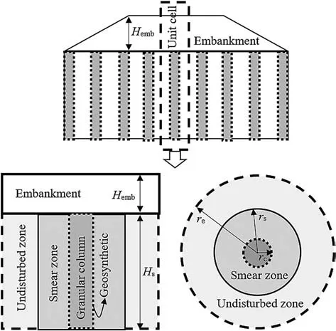
Fig.1. Unit cell idealization. Hs is the thickness of soft soil, and Hemb is the embankment height.
2.3. Axisymmetric model
The performance of geosynthetic-encased end-bearing and floating granular columns and the geosynthetic-layered granular columns was analyzed by the finite element program PLAXIS 2D.The vertical displacements are allowed in the unit cell boundaries(Figs. 2 and 3). The horizontal displacements at the sides (roller boundary condition)and the vertical and horizontal displacements at the base were fixed.
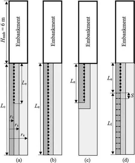
Fig. 2. Axisymmetric modeling: (a) Partial encasement, (b) Full encasement, (c) Fully encased floating column, and (d) Combination of encasement and layering (disks of geogrid).
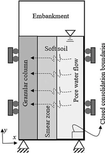
Fig. 3. Boundary conditions of the axisymmetric unit cell.
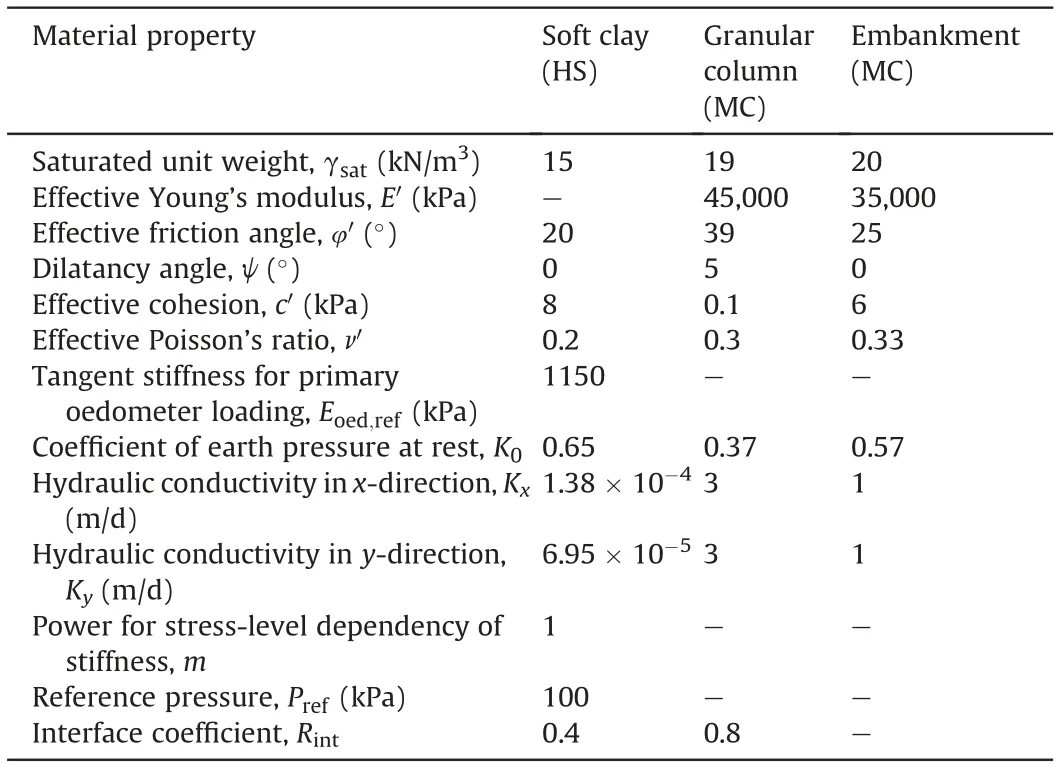
Table 1 Material parameters in finite element model.
As shown in Fig. 2, the encased granular column was studied using full and partial geosynthetic encasement. In the latter case,the length of encasement (Le) is less than the length of the endbearing granular column (Lc). In some cases, the column is partly encased(Le)and partly layered(Ll).The column diameter(dc)in all cases is equal to 0.8 m.For the case of floating columns,the column was assumed fully encased.
In the analyses, the thickness of soft soil (Hs) is 10 m, the embankment height(Hemb)is 6 m,and the smear zone radius(rs)is assumed as 1.9 times the column radius (rc= 0.4 m) (Alkhorshid et al., 2019). The HS and MC models were adopted to model soft soil (Schanz, 1998) and granular column, respectively. The geosynthetics were simulated using a linear elastic model with tensile stiffness (J) equal to 2000 kN/m. The interface elements were introduced on the sides of geosynthetics to consider the interaction with soft soil and column material, and the interface coefficient(Rint) listed in Table 1 was assigned to take into account this interaction. No tensile failure of the geosynthetic encasement was assumed in the analyses carried out and the constraint provided by the geosynthetic is considered by its tensile stiffness. The permeability of the soil within the smear zone in the horizontal and vertical directions was assumed to be identical and equal to 1.38 × 10⁻⁵m/d (Gäb et al., 2008).
In all cases, coupled consolidation analyses were considered to evaluate the excess pore water pressure and primary consolidation settlement of the granular column and surrounding soil within the column influence zone. The water level was assumed at the soilcolumn surface, and impervious boundaries were assigned at the boundaries of the unit cell, as shown in Fig. 3. The consolidation calculations were continued until the minimum pore water pressure(less than 1 kPa)was accomplished.The properties of the soil,column fill and embankment used in the parametric analyses are given in Table 1.
2.4. Model calibration for partially, fully encased and conventional columns
Ali (2014) carried out laboratory tests to evaluate the influence of encasement on granular column performance. The soft soil was prepared at a water content of 40% to reach an undrained shear strength of 6-7 kPa. The end-bearing columns consisted of stone grains with a relative density of 60%,resulting in an internal friction angle of 45°obtained from direct shear tests. The columns were installed with a diameter of 50 mm and a length of 450 mm. The results showed that the full encasement significantly contributed to the maximum column failure stress compared to partially encased and conventional columns(hereafter the granular columns without geosynthetic encasement will be referred to as conventional columns).For model calibration in the present study,an axisymmetric unit cell was considered to model partially, fully encased and conventional columns, as shown in Fig. 4. The geotextile had a normal stiffness of 30 kN/m.The properties of the column and soft soil used in the calibration are given in Table 2. The parameters used for model calibration were obtained from the properties provided by the previous studies (e.g. Oh et al., 2007; Ali, 2014;Alkhorshid et al.,2019)and using the soil test tool in PLAXIS 2D and back analysis. As shown in Fig. 5, the numerical (FEM) analysis results compared well with those of laboratory tests.
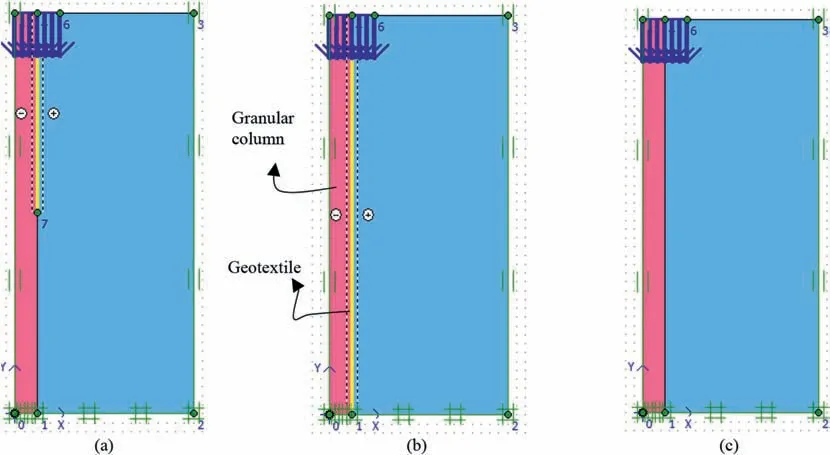
Fig. 4. Model calibration: (a) Partially encased column, (b) Fully encased column, and (c) Conventional column.
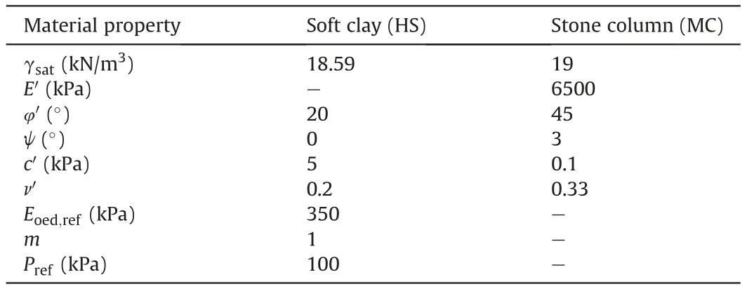
Table 2 Material properties assumed by the present study for model calibration of encased and conventional columns.
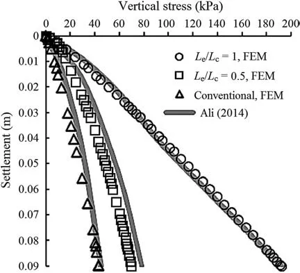
Fig. 5. Model calibration for encased and conventional columns.
2.5. Model calibration for consolidation of soft soil improved by granular column
Oh et al.(2007)presented a study on a trial embankment on soft soil (undrained shear strength Su= 5-20 kPa) improved by granular columns with the spacings of 2 m and 3 m in a square pattern.The results showed that the columns with 2 m spacing underwent less settlement than those of 3 m spacing and those of the embankment with no ground improvement.An axisymmetric unit cell model (Fig. 6) was used to verify the column consolidation settlements.The properties of materials used to model field tests in the present study are presented in Table 3. The results obtained from the numerical analysis are in fair agreement with those of the field tests (Fig. 7).
2.6. Model calibration for dissipation of excess pore water pressure
Alkhorshid et al. (2019) carried out a series of large-scale laboratory tests to evaluate column installation and behavior in a very soft soil (Su= 2 kPa). The study adopted the displacement installation method for column execution. Two piezometers were installed close to the column at the bottom of the test tank to measure the excess pore water pressure due to the column installation in the soft soil. The displacement installation method was modeled by causing a cavity expansion (Castro and Karstunen,2010) using prescribed lateral displacements (Fig. 8). The properties of the soil used in the FEM are given in Table 4. The results obtained from the FEM compared reasonably well with those from the tests,as shown in Fig. 9.
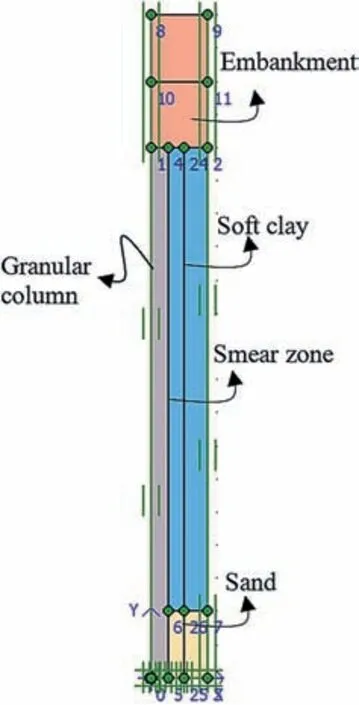
Fig. 6. Model calibration of a trial embankment.
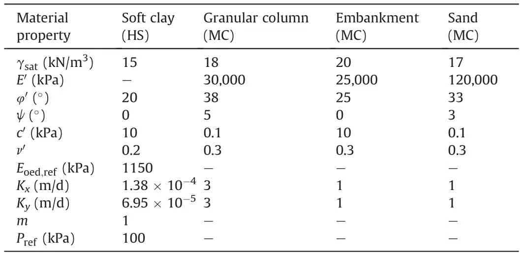
Table 3 Material properties assumed by the present study for model calibration of a trial embankment.
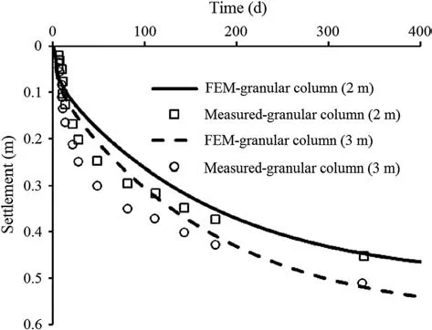
Fig. 7. Model calibration for consolidation settlement.
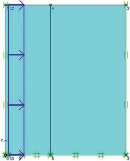
Fig. 8. Model calibration for the displacement installation method.
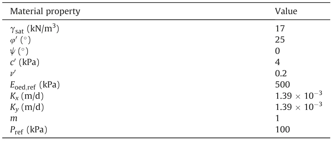
Table 4 Soft soil parameters used in FEM simulation.
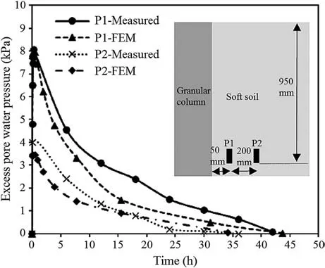
Fig. 9. Model calibration for the dissipation of excess pore water pressure.
3. Parametric study
In parametric study, the results of the fully encased floating column, as well as the results of the partial encasement and the combination of encasement and layering of the end-bearing column, are presented and discussed. In this study, the geotextile stiffness (J) and the diameter ratio (N = de/dc, where deis the column influence zone diameter and dcis the column diameter) are equal to 2000 kN/m and 2.5, respectively, except for the cases in which these values (J and N) are considered as variables.
3.1. Fully encased floating column
Fig.10 shows that the floating ratio(ρ = Le/Hs) has an essential role in the settlements experienced by the column and surrounding soil, since the smallest settlements were obtained for ρ = 1(encased end-bearing column) which showed an improvement of 300% in comparison to the case of ρ = 0.1. On the other hand, as ρ grows, the differential settlements increase so that the smallest differential settlements are obtained for ρ = 0.1 and 0.3.
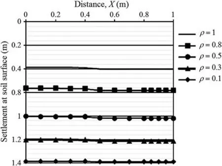
Fig.10. Settlement at the soil surface for different floating ratios (ρ).
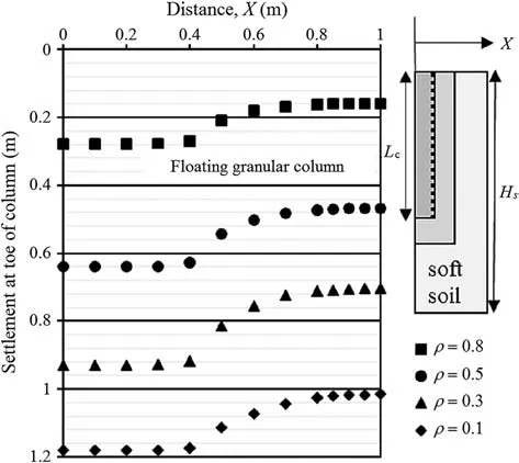
Fig. 11. Settlement (punching settlements) at the column tip for different floating ratios (ρ).
Fig. 11 shows how the floating column can enhance punching settlements of the soft soil when the soil beneath the column tip is not resistant enough to support it or for low values of ρ. By considering the settlements at the soil surface(Fig.10)and of the column tip (Fig. 11), the column with ρ = 0.1 showed higher values of punching settlements than the columns with greater floating ratios.This column(ρ=0.1)exhibited similar settlements at the column top and tip (Figs.10 and 11), but as the floating ratio increased, the tip settlements became smaller than those at the column top.
Fig. 12 shows the shear strain patterns developed above the encased column. Shear bands on the top of the column and surrounding soil increase in size for increasing values of ρ.This figure also shows a triangular plastification zone at the floating column tip as a consequence of punching settlements.The triangular zone(soil wedge)at the floating column tip becomes more significant as ρ is reduced,which implies that lower values of ρ can enhance the punching settlement mechanism at the column tip.
The variation of the normalized column settlement (μ = Sc/Hs,where Scis the settlement on the top of the columns)with time is depicted in Fig. 13. The larger the floating ratio, the smaller the consolidation settlement. This figure illustrates that the conventional column presents a better performance than the columns with ρ = 0.1, 0.3 and 0.5. When ρ reaches 0.8, the column settlements decrease considerably compared to the end-bearing conventional column.The end-bearing encased column shows a better performance, considering the consolidation time and settlements.The column settlements decrease by factors of 3 and 2 compared to that of the column with ρ = 0.1 and the end-bearing conventional column, respectively.
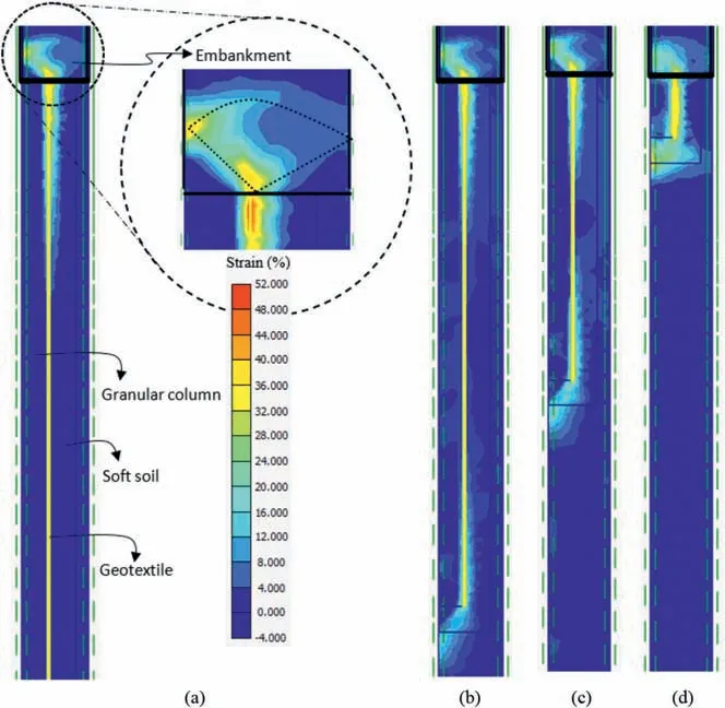
Fig.12. Shear strain patterns: (a) End-bearing column, (b) Column with ρ = 0.8, (c) Column with ρ = 0.5, and (d) Column with ρ = 0.1.
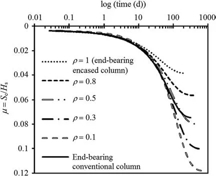
Fig.13. Settlement at the top of column for different floating ratios.
Point A(Fig.14),located close to the bottom of the soft soil layer,was chosen to evaluate the excess pore water pressure dissipation.Thus,it takes much more time for the system to dissipate the pore water pressure produced at this point. The dissipation of excess pore water pressure (at point A) for the column with ρ = 1 was improved significantly by 320%, 240% and 180% compared to the columns with ρ=0.1,0.5 and 0.8,respectively.It shows the effect of the floating factor on radial drainage and, consequently, on reducing drainage paths.
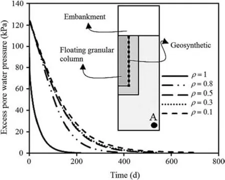
Fig.14. Dissipation of excess pore water pressure for floating columns.
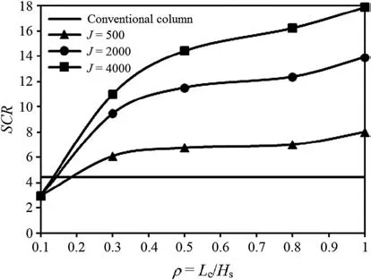
Fig.15. Stress concentration factor versus floating ratio.
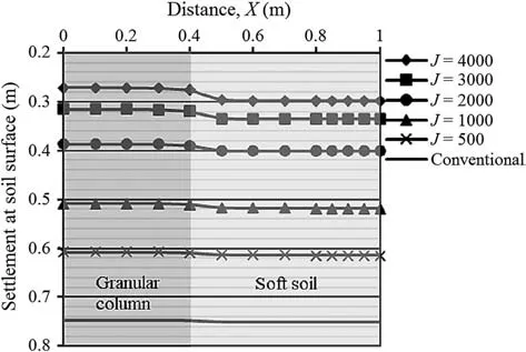
Fig.16. Settlement at the soil surface for different values of geosynthetic stiffness.
Fig.15 shows the effects of the floating ratio and geosynthetic tensile stiffness(J)on the stress concentration ratio(SCR=σv,c/σv,s,where σv,cand σv,sare the vertical stresses supported by the column and surrounding soil,respectively).The stress points considered for the column and surrounding soil were chosen from the points close to the axis of symmetry and the soft soil lateral boundary(at the top of unit cell), respectively. SCR for the column with ρ = 0.1 is less than that of the conventional column, but as ρ increases to values greater than 0.2, the column becomes capable of carrying higher vertical stresses than those carried by the conventional column.Different studies in the literature showed the importance of the geosynthetic stiffness on column performance (Almeida et al.,2013; Hong et al., 2017; Alkhorshid et al., 2018). By increasing J,SCR increases, except for the column with ρ = 0.1, for which no improvement can be noted with increasing values of J.
3.2. Partially and fully encased end-bearing columns
As shown in Fig. 16, the surface settlement decreases with increasing encasement tensile stiffness (J). When J reaches 4000 kN/m, the column settlement decreases by a factor of 2.7 compared to that of the conventional column. On the other hand,the differential settlements in between columns increase as J increases, with the highest value of differential settlements being observed for the encased column with J=4000 and the lowest one for the conventional column.
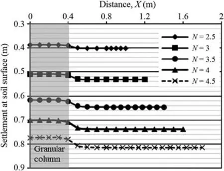
Fig.17. Settlement at the soil surface for different values of N.
The diameter ratio (N = de/dc) directly influences column performance,as shown in Fig.17.When N increases,both consolidation and differential settlements increase. For N = 2.5, both the consolidation and differential settlements are approximately 50%smaller than those for N = 4.5 (Fig.17).
Fig.18 illustrates the influence of N on the normalized column settlement (μ). It can be noted that it will take more time for significant soft soil consolidation to take place as N increases.N values equal to 2.5 and 4.5 yield the lowest and highest times needed for primary consolidation to be completed, respectively. This is also observed for the dissipation of excess pore water pressure at point A(Fig.19).As N increases from 2.5 to 4.5,the time required for the dissipation of excess pore water pressure at that point increases by a factor of 5.7.
Fig. 20 shows the settlement reduction factor (β = reinforced column settlement/conventional column settlement) versus time.The length of encasement influences both the consolidation settlement and time.For a length of encasement(Le)equal to 6 times the diameter of column (dc) and for the fully encased column, the settlement(for 200 d)decreases by 21%and 43%,respectively,with respect to a value of Le= 2dc.
The behavior of partially encased columns can be improved by reinforcing the column’s uncased portion using geosynthetic disks(layered portion, Ll). For the column partially encased (6dc), by adoption of a distance (S) between two consecutive disks equal to 0.3 m(S=0.38dc),the column behaves like the fully encased endbearing one.For this column(6dc),as S reduces to values less than 0.38dc(e.g. S = 0.2 m), it performs better than the fully encased end-bearing column. Hosseinpour et al. (2014) concluded that the fully layered column settles as equal as the fully encased column when S is adopted as 0.25dc.
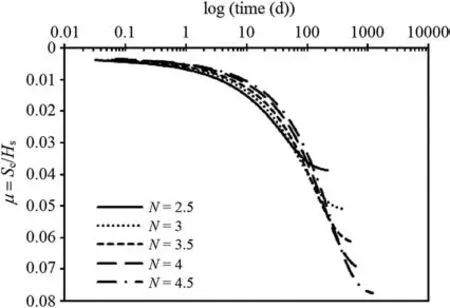
Fig.18. Settlement at the top of the column for different values of N.
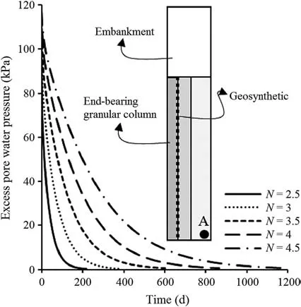
Fig.19. Dissipation of excess pore water pressure at point A for different values of N.
4. Conclusions
In this study, the effects of the floating ratio and the geosynthetic encasement length and type were evaluated using FEM.The conclusions can be drawn as follows:
(1) By increasing the floating ratio(ρ),the differential settlement increases, and consolidation settlement decreases. As the floating ratio increases, the times needed for dissipation of excess pore water pressure and consolidation settlement being accomplished decrease considerably. On the other hand, the reduction of the floating ratio enhances the punching settlements.
(2) In the present study, the column with ρ = 0.5 and J=2000 kN/m settles like the conventional column,but the time for consolidation settlement increases by a factor of 1.72 compared to that of the conventional column. On the other hand, the column with J ≥500 kN/m and ρ > 0.2 presents greater SCR values than the conventional column.
(3) The increases of the tensile stiffness(J)and diameter ratio(N)yield higher values of the differential settlements for the end-bearing encased column. By contrast, the consolidation settlement decreases as J increases and N decreases.
(4) By decreasing N from 4.5 to 2.5 (a difference of 2), the ultimate times needed for dissipation of excess pore water and consolidation settlements of the end-bearing encased column are reduced by factors of 5.7 and 4.6, respectively.
(5) For partially encased columns, as the length of encasement(Le) increases, the settlement decreases. For the partly encased column with Le= 6dcand partly layered (Ll, with S = 0.38dc), the column acts like the fully encased endbearing one and results in a reduction of 18% of geosynthetic used.Besides,when S is reduced to values less than 0.38dc, the column produces smaller settlements than the fully encased end-bearing column.
Declaration of competing interest
The authors wish to confirm that there are no known conflicts of interest associated with this publication, and there has been no significant financial support for this work that could have influenced its outcome.
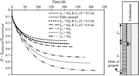
Fig. 20. Settlement reduction factor (β) for different types of column reinforcement.
 Journal of Rock Mechanics and Geotechnical Engineering2021年5期
- Journal of Rock Mechanics and Geotechnical Engineering的其它文章
- Surface characteristics analysis of fractures induced by supercritical CO2 and water through three-dimensional scanning and scanning electron micrography
- Prediction of fracture and dilatancy in granite using acoustic emission signal cloud
- Hysteresis in the ultrasonic parameters of saturated sandstone during freezing and thawing and correlations with unfrozen water content
- Coupled Eulerian-Lagrangian simulation of a modified direct shear apparatus for the measurement of residual shear strengths
- A novel true triaxial test system for microwave-induced fracturing of hard rocks
- Hydromechanical behavior of unsaturated expansive clay under repetitive loading
