Laboratory large-scale pullout investigation of a new reinforcement of composite geosynthetic strip
Mehrdad Tajaadipour, Seyed Hamid Lajevardi
a Department of Civil Engineering, Sirjan University of Technology, Sirjan, Iran
b Department of Civil Engineering, Arak Branch, Islamic Azad University, Arak, Iran
Keywords:Pullout resistance Composite geosynthetic strip (CGS)Soil-geosynthetic interface Scrap tires Large-scale pullout tests
ABSTRACT In this paper, more than 70 large-scale pullout tests were performed to evaluate the performance of an innovative composite geosynthetic strip(CGS)reinforcement in sandy backfill.The CGS reinforcement is composed of a geosynthetic strip (GS) and parts of a scrap truck tire as transverse members. The experimental pullout results for the CGS reinforcement were compared with the suggested theoretical equations and ordinary reinforcements,including the GS,the steel strip(SS),and the steel strip with rib(SSR). The pullout test results show that adding three transverse members to the GS reinforcement(CGS3)with S/H=6.6(where S and H are the space and height of the transverse members,respectively)increases pullout resistance by more than 120%,170%, and 50% compared to the GS, the SS, and the SSR,respectively.This result shows that the CGS3(CGS with three transverse members)reinforcement needs at least 55.5%, 63%, and 33.3% smaller length compared to the GS, the SS, and the SSR, respectively. In general,implementation of mechanically stabilized earth wall(MSEW)with the proposed strip may help geotechnical engineers prevent costly designs and solve the problem of MSEW implementation in cases where there are limitations of space.
1. Introduction
Mechanically stabilized earth wall (MSEW) has been widely used in geotechnical engineering projects because of easier implementation, lower construction cost, and higher flexibility against seismic loads.Various experimental studies have shown the excellent performances of MSEW(Cristelo et al.,2015;Wang et al.,2015; Mirmoradi et al., 2016; Saghebfar et al., 2017; Yazdandoust,2017; Sadat et al., 2018). MSEW consists of three elements, i.e.the backfill, the reinforcement, and the concrete precast panels.Based on Berg et al. (2009), the reinforcements used in MSEW are classified into two groups,i.e.extensible and inextensible.Geogrid and polymeric strips are extensible because of their higher level of deformation at failure compared to the deformability of the soil.The vital parameter in internal stability is the interaction between the soil and the reinforcements.Thus,investigations about various factors that affect the interaction between different reinforcements and the soil can help geotechnical engineers achieve an economical and sustainable design.The pullout force of various reinforcements consists of three sections, i.e. the interaction with the soil in the opening,the frictional resistance,and the bearing resistance of the transverse members (Jewell et al.,1984). Direct shear and pullout tests have been used to determine the interaction between the soil and the reinforcements in many studies(Bergado et al.,1987,1992;Jewell and Wroth,1987; Palmeria and Milligan,1989; Ochiai et al.,1992; Fannin and Raju, 1993; Farrag et al., 1993; Palmeira, 2004,2009;Teixeira et al.,2007).Different researchers have attempted to design an apparatus for measuring the pullout resistance of various reinforcements (Palmeria and Milligan, 1989; Lupo et al., 1990;Bergado et al., 1992; Ochiai et al., 1992; Fannin and Raju, 1993;Farrag et al., 1993; Alfaro et al., 1995; Lopes, 1999). The rate of applying the pullout force is one of the important parameters for pullout tests. The results of various pullout tests revealed that an increase in the speed of applying the pullout force causes a decrease in the pullout resistance (Farrag et al., 1993). Thus, the American Society for Testing and Materials(ASTM)standard(ASTM D6706-01, 2013) suggested a rate of (1 ± 0.1) mm/min for performing pullout tests. The pullout resistance and the interaction between the soil and the reinforcements are influenced by the boundary conditions of the pullout test box.Different studies have attempted to eliminate or decrease the effects of the sidewalls of the box (Bergado et al.,1987; Palmeria and Milligan,1989; Alfaro et al.,1995; Moraci and Recalcati, 2006). Various methods or materials have been suggested for decreasing the effects of the sidewalls of the box,such as lubrication using silicon grease or a rubber member, a latex membrane and polyvinyl chloride (PVC) (Fannin and Raju, 1993; Alfaro et al., 1995; Lo, 1998; Moraci and Gioffrè,2006; Khedkar and Mandal, 2009; Abdi and Zandieh, 2014; Alam et al., 2014). Two sleeves with width of 200 mm and thickness of 10 mm suggested by ASTM D6706-01 (2013) were used to reduce the front wall effects.
Over the last few decades,experimental pullout tests have been conducted on various reinforcements.The results of various pullout tests revealed that the dimensions of geogrid samples (i.e. width and length of geogrid) and the soil’s height above and below the geogrid sample, are important factors that affect the pullout resistance(Lopes and Ladeira,1996a,b;Lopes,1999;Liu et al.,2009;Hatami et al., 2013; Han et al., 2018). Some dimensional parameters,such as the length of the geogrid,are a function of the granular soil density (Lopes and Ladeira,1996a, b). Research involving the soil and geogrid interface revealed that the aperture size and the aggregate’s properties play an important role in the pullout resistance (Lopes,1999; Liu et al., 2009; Han et al., 2018; Hatami et al.,2013). Studies involving clay reinforced with geogrid encapsulated in thin layers of sand can be found in Abdi and Arjomand(2011) and Abdi and Zandieh (2014).
Many efforts have been made to develop analytical and numerical methods to evaluate the performance of reinforcements under the pullout force (Jewell et al.,1984; Palmeria and Milligan,1989; Gurung and Iwao,1999; Moraci and Gioffrè, 2006; Bathurst et al., 2012; Mohan et al., 2016; Cardile et al., 2017; Yu and Bathurst, 2017).
Recently, researchers have attempted to use innovative approaches to increase the bearing resistance and decrease the length of the reinforcements (Esfandiari and Selamat, 2012;Suksiripattanapong et al., 2013; Mosallanezhad et al., 2015, 2016a,b; Sadat-Taghavi and Mosallanezhad, 2017).
In recent years,investigating scrap tires in an attempt to provide a solution for the problem of scrap tires has become an interested topic. Numerous scrap tires have been abandoned in nature,causing air and environmental pollution. To solve this problem, a large number of studies have attempted to propose various ways to utilize scrap tires in different areas of civil engineering, including filler in retaining walls (Lee et al.,1999; Shrestha et al., 2016) and drainage systems (Reddy and Saichek, 1998), dampers and materials to increase the resistance against liquefaction (Tsang, 2008;Bandyopadhyay et al., 2015; Senetakis and Anastasiadis, 2015) in roads, backfill materials for MSEW (Abichou et al., 2004 Balunaini and Prezzi, 2009; Balunaini et al., 2014; Mohan et al., 2016;Tajabadipour and Marandi, 2017; Ghaaowd and McCartney, 2020)in embankments and cut-off walls (Bosscher et al., 1997;Bandyopadhyay et al., 2015; Chegenizadeh et al., 2018) in foundations (Yoon et al., 2004; Edeskär, 2006; Hataf and Rahimi, 2006),and as reinforcements in MSEW (Tajabadipour et al., 2019).
Currently, geosynthetic strip (GS) (or polymeric strip) has become one of the prevalent reinforcements for MSEW. Research involving the interface between the soil and the GS under static or cyclic loading conditions can be found in Razzazan et al. (2018,2019) and Abdelouhab et al. (2010, 2011, 2012).
GS has a smooth surface and a higher pullout resistance due to the frictional force with soil. Therefore, providing a solution to increase the bearing resistance can enable geotechnical engineers to achieve more accurate and economical designs.
This study evaluated the performances of a new composite geosynthetic strip(CGS)reinforcement based on large-scale pullout tests (i.e. 1.4 m × 0.8 m × 0.8 m) under three normal stresses of 25 kPa,50 kPa,and 75 kPa.The CGS reinforcement consists of a GS as a longitudinal member and scrap tire elements as transverse members. The transverse members were extracted from sidewalls of a scrap truck tire(385/80/R22.5).To examine the performance of the CGS,the results of the pullout tests were compared with those obtained for conventional strip reinforcements,including the steel strip (SS), the steel strip with rib (SSR), and the GS. Theoretical equations were proposed for predicting the pullout resistance of the CGS.The proposed reinforcement helps geotechnical designers implement MSEW in urban areas,where the required length of the strip is not available.MSEW projects become more cost-effective by utilizing the CGS.
2. Materials and methods
2.1. Soil samples
In this study,the soil was selected based on Berg et al.(2009)for the filler material in the large-scale pullout tests, and it was classified as poorly-graded sand (SP) according to unified soil classification system (USCS). The particle size distribution (PSD) is depicted in Fig.1. The compaction characteristics of the tested soil(i.e. the maximum unit weight γdmaxand optimum water content wopt) were obtained from the Proctor tests based on the standard Proctor energy (ASTM D698-07, 2007)(Table 1).
The large-scale direct shear box was utilized to decrease the scale effect.In this regard,different parameters for performing the direct shear tests were selected based on the same conditions as in the pullout tests. The results of the direct shear tests (cohesion c and internal friction angle φ) are summarized in Table 1.
2.2. Reinforcements
2.2.1. Geosynthetic strip reinforcement
GS is made of polyester fibers surrounded by a polyethylene sheath, and the different tendons are created through a vacuum die-coating process.The straps are manufactured based on several grades and thicknesses.In this study,the GS with thickness of 2 mm and width of 90 mm was used (Fig. 2). The length of the GS was selected based on the length of the pullout apparatus,i.e.850 mm.Different characteristics of the GS are summarized in Table 2.
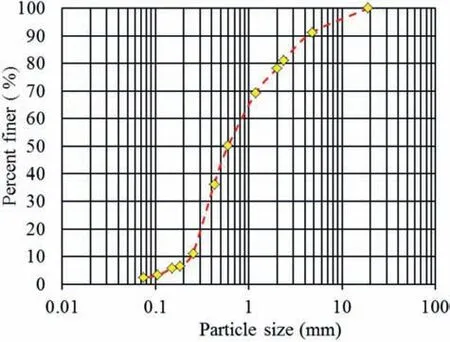
Fig.1. Particle size distribution curve.
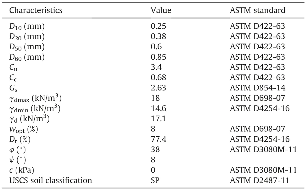
Table 1 Soil characteristics in this study.
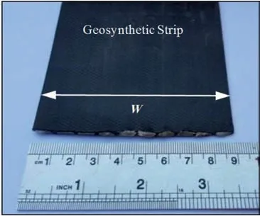
Fig. 2. Geosynthetic strip.
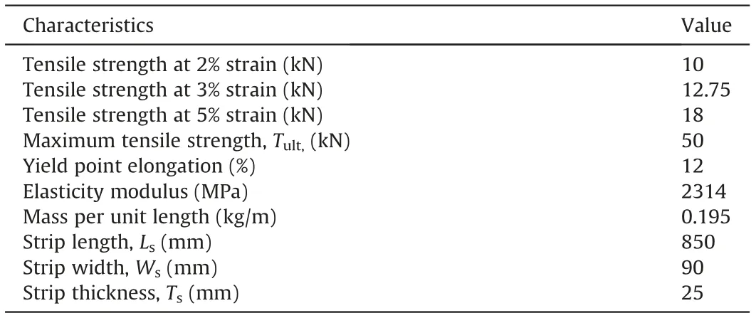
Table 2 Characteristics of geosynthetic strip.
2.2.2. Steel strip reinforcements
Two types of SS reinforcements,i.e.the smooth SS and the SSR,are used to compare the GS reinforcement as conventional strip reinforcements.The galvanized SS with thickness of 4 mm,width of 90 mm,length of 850 mm,and tensile strength of 65 kN was used in the pullout tests(Fig.3a).The dimensions for the SSR are the same as those of the SS.The thickness of the ribs is 2 mm,repeating with an interval of 50 mm along the length of the SS (Fig. 3b).
2.2.3. Composite geosynthetic strip (CGS) reinforcements
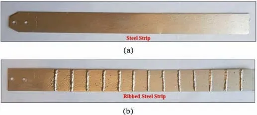
Fig. 3. Conventional strip reinforcements: (a) Steel and (b) ribbed steel strips.
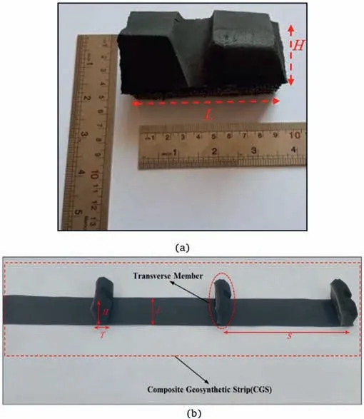
Fig. 4. (a) Transverse member and (b) composite geosynthetic strip.
Transverse members play important roles in the passive resistance of the reinforcement. In this study, elements of scrap tires were used as transverse members on the top surface of the GS. To do so, a scrap truck tire was used and its two sidewalls were separated. In the next step, the embossed strip of scrap tire was divided into elements with the desired dimensions.The dimension of the transverse members is 20 mm in thickness(T)and 90 mm in length(L)(Fig.4).To connect transverse members on the surface of the GS, the surfaces of the transverse and longitudinal members were thoroughly cleaned firstly.Then,using high-strength adhesive and the cold splicing methods, the transverse members were attached to the GS.A normal stress of 120 kPa was applied to ensure the connection performance of the transverse members, and as a result,no displacement or rupture was observed in the connection.
2.3. Methodology
The performances of the new proposed reinforcements were evaluated with large-scale pullout tests. In this study, the pullout device was manufactured based on ASTM D6706-01(2013)(Fig.5).The horizontal and vertical forces were applied by a hydraulic force actuator and a pneumatic airbag. The linear variable differential transformer (LVDT) and the load cell with 150 mm and 100 kN capacity were used to measure the displacement and the pullout force.
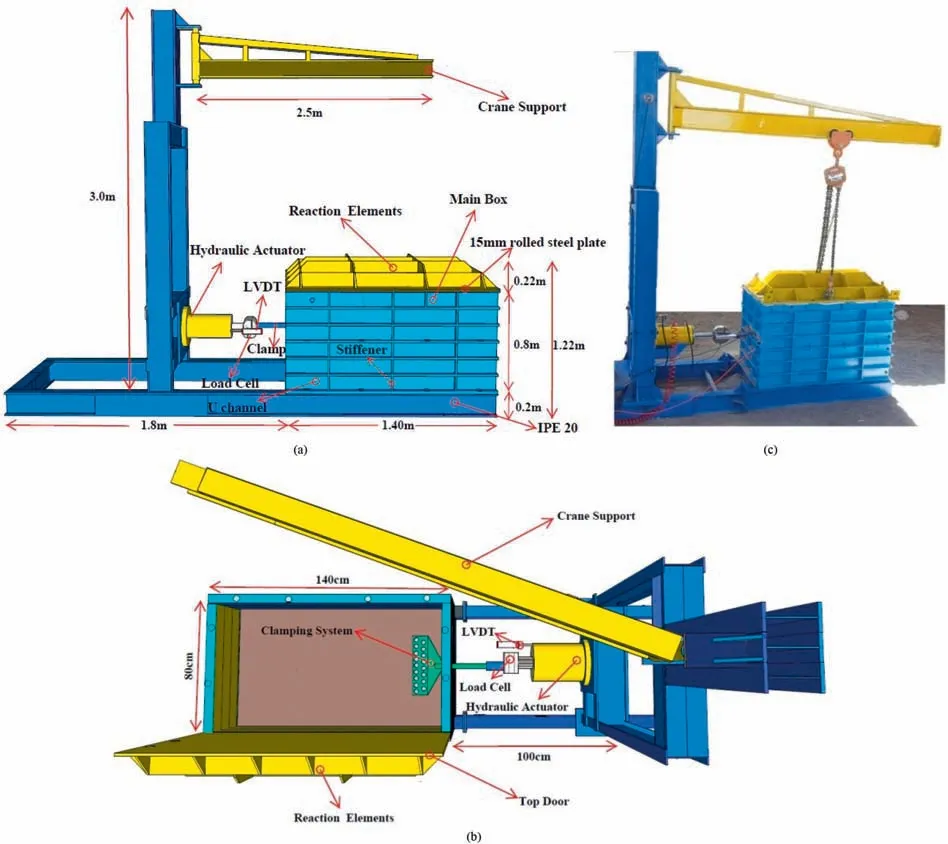
Fig. 5. Large-scale pullout apparatus: (a) Section, (b) plan, and (c) three-dimensional (3D) picture.
When performing pullout tests, decreasing or eliminating the effects of the friction between the soil and various sidewalls of the box will be an important issue.In this study,to decrease the effects of the front wall of the box,two sleeves with width of 200 mm and thickness of 10 mm were utilized.No particular method was used to reduce the friction of the walls,except for using a distance of more than 150 mm between the reinforcement and each wall,according to ASTM D6706-01 (2013).
The clamping system can be placed outside or inside the pullout box. In the external clamping system, the entire reinforcement is not in contact with the soil, and the pullout force is applied to the first node of the reinforcement that is out of the box.In the internal clamping system,the pullout force is applied to the first node of the reinforcement that is confined in the soil, and the entire reinforcement is in contact with the soil. Based on the abovementioned points, the internal clamping system was used in the current study.
To reach a compaction with a relative density of 77.4%, a hammer with size of 0.2 m × 0.2 m and weight of 0.08 kN was utilized. To obtain uniformly-compacted layers, various soil layers were compacted by being tamped down with three blows of the hammer (hammer dropped from height of 250 mm). When the thickness of the soil layers reached 360 mm, the reinforcement elements (i.e. GS, SS, CGS, or SSR) were attached to the clamping system.Then,the end of the clamp was connected to the hydraulic actuator. In the next step, four layers of soil with thickness of 90 mm and similar relative density of the bottom layers were placed on the upper part of the box.
To determine the uniformity of the compacted soil layers, four cans were placed at heights of 180 mm, 360 mm, 540 mm and 720 mm.After measuring the unit weight of the compacted soil in the cans, it was found that the average unit weight was 0.95 ± 0.0058 times the γdmax, showing that different layers were uniformly compacted.
3. Results and discussion
3.1. Pullout resistance of the reinforcements
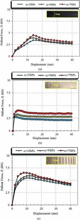
Fig.6. Pullout force versus displacement for different strips:(a)geosynthetic strip,(b)steel strip, and (c) steel strip with rib.
The pullout force for all the reinforcements increases until reaching the peak force (Pf), and with increase in the normal stress, Pfincreases (Fig. 6). Overcoming the interlocking between the particles of the dense sand causes the pullout force to reach a peak value. After the peak, the soil failure results in more displacement, and the pullout resistance decreases (the strainsoftening behavior). The peak force (Pf) for different reinforcements takes place at different displacements. Among different reinforcements, the displacement required to reach the peak force in the GS is the highest, and this value is almost constant (14-16 mm) at different normal stresses. The required displacement for reaching the peak force for the SSR under different normal stresses is 10-12 mm.The displacement to reach the maximum pullout force for the GS and the SSR is higher than the other reinforcements because the GS and the SSR have a rib on the top or the bottom surface. In the SS reinforcement, the displacement required to reach the peak force is the lowest (2-4 mm) (this is due to the smooth surface of the SS).
The pullout resistance ratio of different reinforcements(PRRD)is defined to compare pullout resistances of various reinforcements:

Fig.7 presents the PRRDfor three reinforcements,i.e.GS,SS,and SSR.By increasing the normal stress,the PRRDof the SS and the SSR decreases and increases, respectively. Compared with SS, the pullout resistance of GS increases by an average of 20%.This is due to a small rib at the top and the bottom surface of the GS,while the SS has a perfectly smooth surface. For the SSR, the PRRDdecreases,suggesting that the pullout resistance of SSR is, on average, 33%higher than that of the GS reinforcement.
3.2. Pullout resistance of CGS with one transverse member
As noted in the previous sections, the bearing resistance is an important part of the pullout resistance.Therefore,the sidewalls of the scrap tires are utilized as bearing members(Fig.4).The height and width of the transverse members for the CGS1(CGS with one transverse member, Tn= 1) are 25-100 mm and 90 mm, respectively. For the GS and the CGS1, the pullout resistance at the peak force is high, and then it gradually decreases (Fig. 8). The granularity of the soil and overcoming the interlocking among different particles of the dense sand cause the pullout force to reach the maximum value.
The pullout resistance increases by adding one transverse member.This result is due to the shift in the behavior of the pullout resistance from frictional to frictional-passive.For both the GS and the CGS1,the displacement required for the full mobilization of the pullout force under all normal stresses is 16-22 mm, and the maximum pullout force of the CGS1is obtained at a higher displacement compared to the GS.
Predicting the bearing resistance of the reinforcement is one of the fundamental issues. Various equations and mechanisms have been proposed to evaluate the bearing resistance.The main bearing failure mechanisms include the general shear failure mechanism(Peterson and Anderson, 1980) (Fig. 9a), the punching failure mechanism(Jewell et al.,1984)(Fig.9b),and the modified punching failure mechanism (Bergado et al.,1996) (Fig. 9c).
The pullout resistance, Pr, at every reinforcement level is expressed by

where L and W are the length and width of reinforcement,respectively;α is the scale effect correction factor;F*is the pullout resistance factor;and σ is the normal stress.The maximum bearing resistance σbmaxis determined as follows:

where Ncand Nqare the bearing capacity factors, and σ is the normal stress.
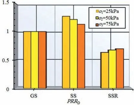
Fig. 7. PRRD of three strips.
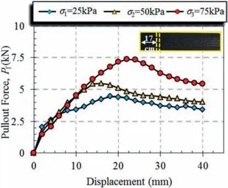
Fig. 8. Pullout test results of composite geosynthetic strip.
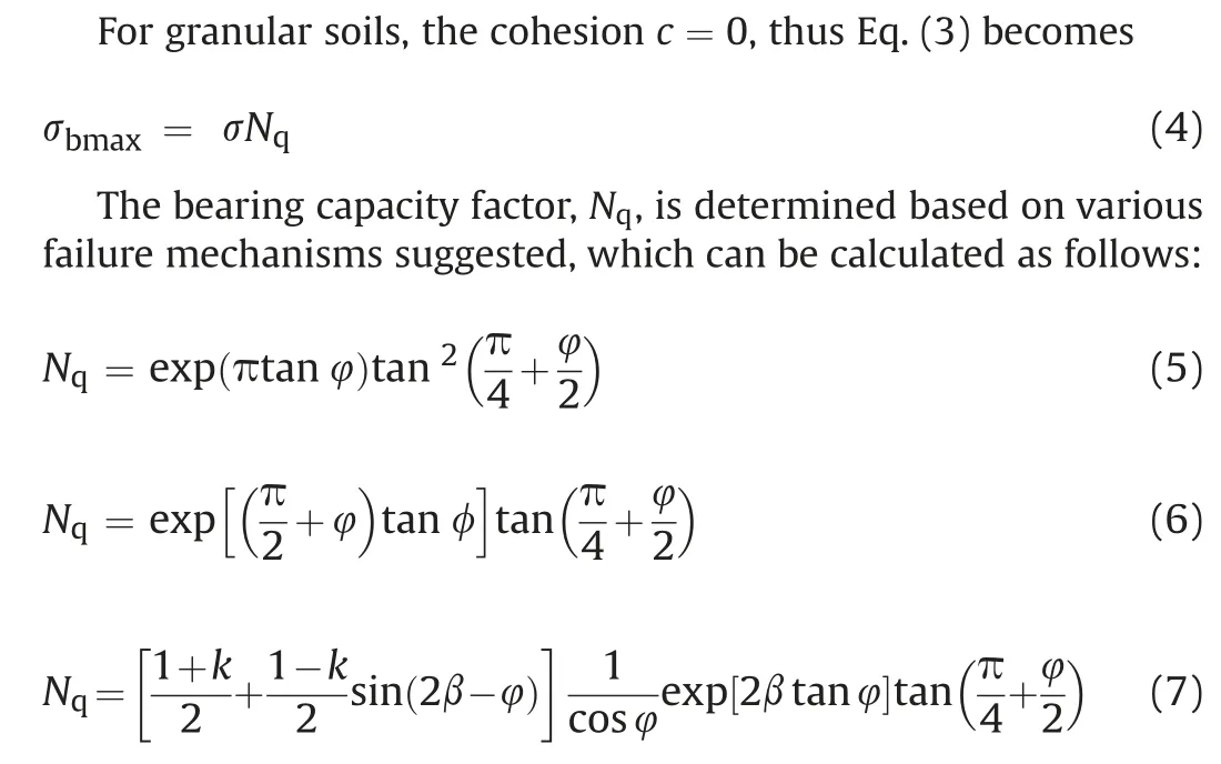
where k and β are the coefficient of the lateral earth pressure and the failure plane angle, respectively. In this study, based on the suggestions in previous studies, the values of k and β are considered as 1 and π/2, respectively (Bergado et al.,1993; Horpibulsuk and Niramitkornburee,2010; Suksiripattanapong et al.,2013).
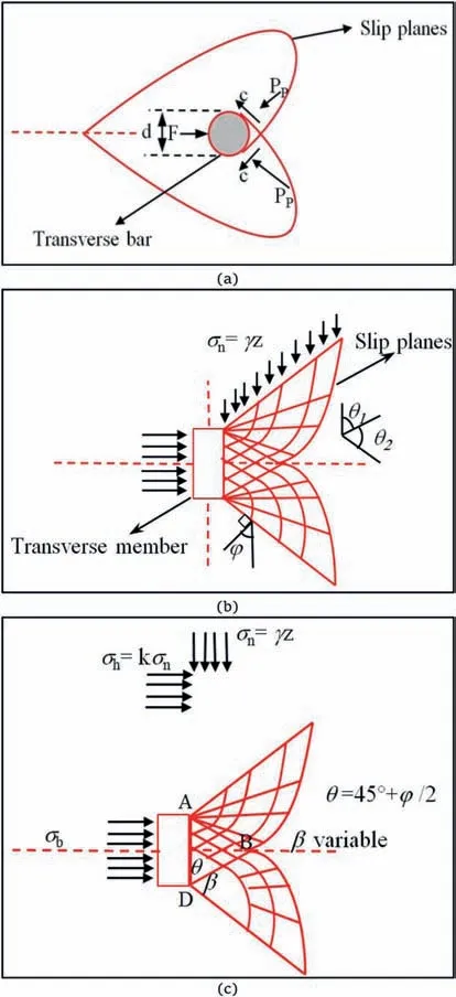
Fig. 9. Failure mechanism of transverse members: (a) General shear failure mode(Peterson and Anderson,1980), (b) Punching shear failure mode (Jewell et al.,1984),and (c) Modified punching failure mode (Bergado et al.,1996).
Fig.10 presents the maximum bearing resistance (σbmax) based on experimental and theoretical results for the CGS1. Under lower normal stress,the punching shear failure mechanism concurs well with the large-scale experimental results. When the height of the transverse member increases, the difference between the theoretical and experimental results decreases. The best agreement is for the height of 50 mm under lower normal stresses. When the normal stress increases, the punching shear failure mechanism predicts higher values compared to the pullout resistance results.To calculate the bearing stress, the bearing factor (Nq) is an important parameter, which can be calculated based on Eqs. (5)-(7) (for the bearing capacity, the internal friction angle of the soil is an important parameter).Therefore,the bearing resistance factor(Nq)based on the failure mechanism,and the friction angle (φ =30°- 45°) is calculated and drawn in Fig.11.
3.3. Pullout resistance of CGS with different transverse members(Tn > 1)
Increasing the pullout resistance becomes possible by increasing the length of the reinforcement. However, in the implementation of some MSEW, there is no possibility to increase the length of reinforcement because of space constraints. In such cases, increasing the pullout resistance by adding transverse members can be one of the best options.
In this paper, a part of the scrap tire is used as a transverse member for the GS reinforcement to increase pullout resistance.Different studies have revealed that the distance between the transverse members is a vital factor for increasing the pullout resistance by adding various transverse members (Palmeria and Milligan,1989; Bergado et al., 1996; Palmeira, 2009; Horpibulsuk and Niramitkornburee, 2010). The distance between two consecutive transverse members is the same,and the number of transverse members changes to achieve the optimal value (Fig.12).
Fig. 13 shows the results of the pullout experiments for CGSn.When there are more than one transverse member, the pullout resistance gradually increases until it reaches the peak force, and then it keeps almost constant with an increase in displacement.
Adding two transverse members to the GS(CGS2)increases the pullout force by more than 80%compared to the GS.
The highest increase in the pullout resistance compared to the GS for all normal stresses was obtained in the CGS3. With an increase in the number of transverse members to more than three(Tn> 3), the pullout resistance decreased because of the interference between various transverse members (Fig.13).
As shown in Fig.13, for the CGS4and CGS5, the increase in the number of transverse members has less impact on the pullout resistance compared to other models. Different studies have investigated the effects of transverse members on the pullout resistance(Esfandiari and Selamat,2012;Suksiripattanapong et al.,2013; Mosallanezhad et al., 2015, 2016a, b). Bergado et al. (1996)determined the effects of the interference of transverse members with various spacing patterns on the pullout resistance in the form of the dimensionless parameter S/D(bearing member spacing ratio,where S and D are the space and diameter of the transverse members, respectively). In this study, in order to evaluate the interference effect and find the optimal number of transverse members,various distances between the transverse members were used.
Fig.14 depicts the relationship between the maximum pullout resistance and the spacing ratio of transverse members, i.e. S/H(where H is the height of the transverse members), under various normal stresses applied. For the S/H values of more than 6.6, the pullout resistance gradually increases, and the maximum pullout resistance is obtained at the ratio of 6.6. With decrease in the S/H ratio, the values of the pullout force decrease. The difference between the pullout results for various normal stresses at the S/H ratio of 6.6 is less than the difference at other values of S/H(Fig.14).
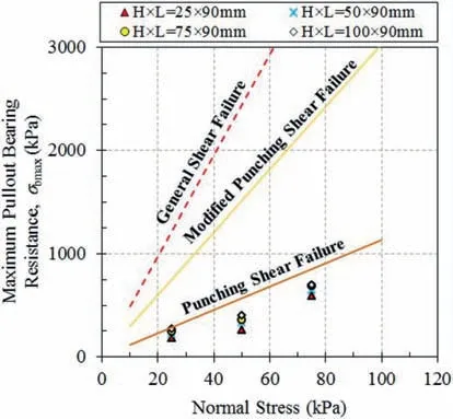
Fig. 10. Maximum bearing resistance (σbmax) based on experimental and theoretical results.
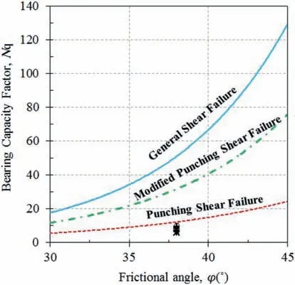
Fig.11. Bearing capacity factors (Nq).
The pullout results illustrated that the space between the transverse members could be a critical parameter for the mobilization of the force in front of the bearing members. Therefore,depending on the choice of the distance between the transverse members, different failure mechanisms (i.e. block failure, interference failure,and individual failure) may occur.
For the S/H ratio of more than 6.6,different transverse members do not interfere with each other, and it seems that the individual failure occurs (Fig. 15a). A decrease in the space between the transverse members increases the interference between various transverse members.
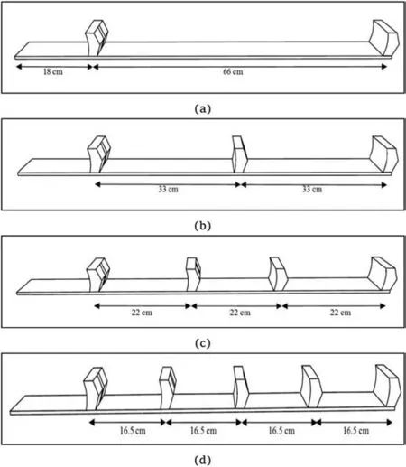
Fig.12. Different transverse members:(a)Tn=2,(b)Tn=3,(c)Tn=4.and(d)Tn=5.
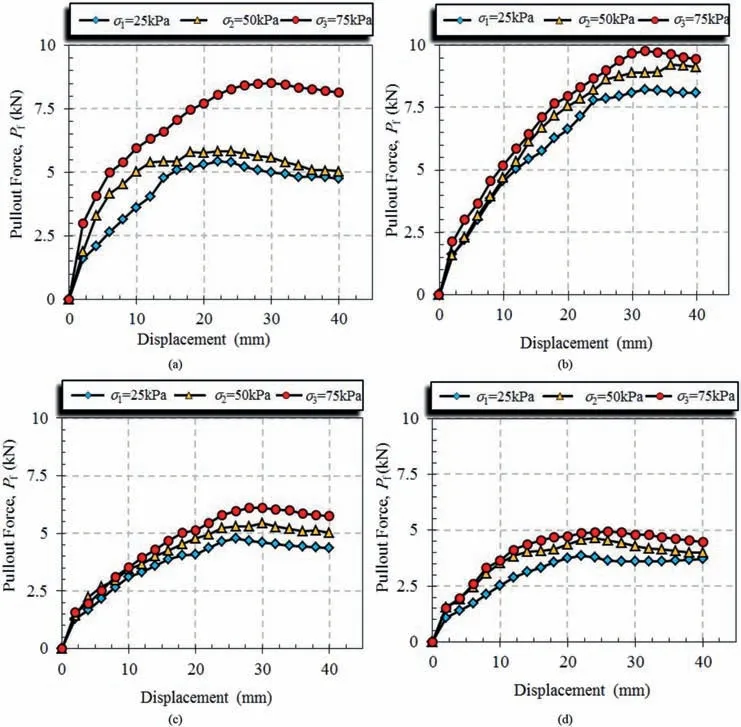
Fig.13. Pullout force versus displacement for different transverse members: (a) CGS2, (b) CGS3, (c) CGS4, and (d) CGS5.
When interference between the transverse members increases,the softening area created behind each transverse member reduced the full mobilization of the force in front of the other members.Accordingly, the pullout force decreases, and the interference(Fig.15b) or block (Fig.15c) failure mechanism occurs.
The transverse members interfere with each other, and decrease the maximum pullout resistance. Among different numbers of transverse members (Tn= 1-5), adding three transverse members results in a higher bearing resistance.To evaluate the effects of the dimensionless ratio of S/H on the pullout resistance and to determine the failure mechanism, one and two transverse members are added at different distances from the first transverse member (the first transverse member is located at a distance of 17 cm from the clamp,and this location is constant in all the tests).
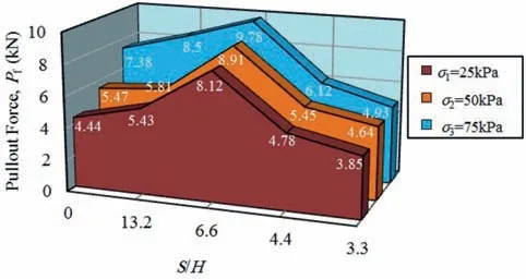
Fig.14. Pullout force versus ratios of S/H.
Fig. 16 shows the maximum bearing resistance (Pbn) for CGSs with two and three transverse members (Tn= 2 and 3) versus the dimensionless ratio of S/H under various normal stresses.As seen in Fig.16 when the spacing ratio (S/H) is more than 10, the interference between the transverse members is insignificant,and various members are free to act.However,when the S/H ratio is less than 4,it is observed that the interference between the transverse members is high,and comparison with the values in Fig.8 revealed that the pullout resistance does not change much compared to the case where a single transverse member is used. Due to the softening area behind the transverse members, this result does not cause force mobilization in front of the other members, and the shear surfaces of various members are joined together.Subsequently,the maximum pullout resistance is obtained from the summation of the frictional resistance of the GS, the block sides,and the bearing resistance of the first transverse member. Based on large-scale pullout test results, depending on the S/H ratio, different mechanisms of bearing failure happened in three zones:(1)Zone I:block failure (when S/H is less than 4); (2) Zone II: interference failure(when S/H is between 4 and 10 for CGS2and between 4 and 6.6 for three CGS3); and (3) Zone III: individual failure (when S/H is more than 6.6 or 10).
The amount of interference between various transverse members can be explained by the interference factor (IF), which is calculated as follows:

Data processing of different results shows that the interference factor (IF) depends on S/H, Tn, and σn. Based on the experimental results of maximum pullout bearing resistance versus the ratio of S/H (Fig.16), the interference factor(IF) can be obtained as follows:

where ζ and λ are the interference factor coefficients,the values of which depend upon the number of transverse members (Tn).
From experimental results, ζ and λ values are -0.415 and -3.69 at Tn= 2, and 0.763 and 2.12 for Tn= 3, respectively.Based on laboratory large-scale pullout test results, the equations for predicting IF are proposed as follows:

where ζ and λ are interference factor coefficients,and Tn,a number of transverse members.
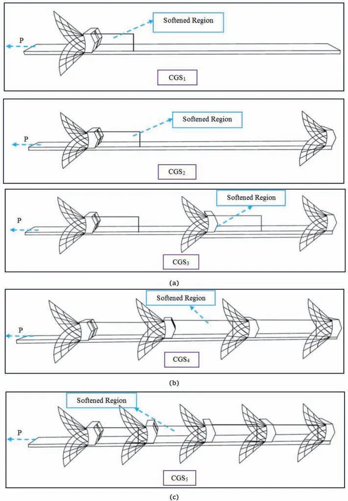
Fig.15. Different bearing failure mechanisms: (a) Individual failure, (b) interference failure, and (c) block failure.
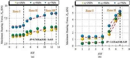
Fig.16. Maximum bearing resistance for different S/H ratios: (a) CGS2, and (b) CGS3.
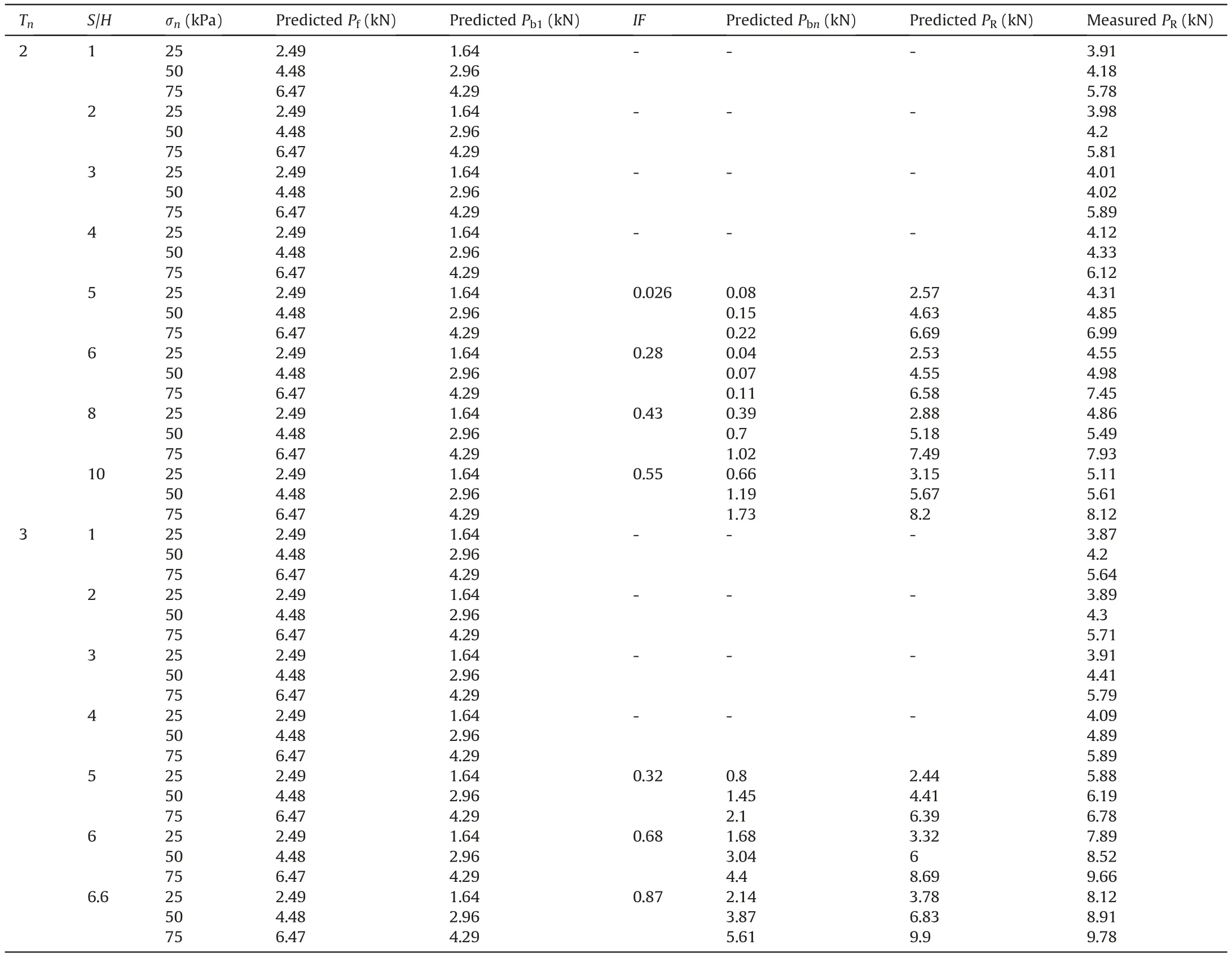
Table 3 Predicted and measured pullout resistances of CGS.
To predict the pullout resistance of the GS(Pf)and the CGS with one transverse member (Pb1), Eqs. (2) and (3)-(7) were used respectively.In the second step,the interference factor(IF)has to be determined. To do so, in the first try, the interference factor coefficient is determined based on the number of transverse members(Tn), the S/H ratio (4-10 for Tn= 2, and 4-6.6 for Tn= 3), and the normal stress(using Eqs.9-11).Furthermore,the predicted Pbnwas assigned based on Eq. (8) for three overburdens and two different numbers of transverse members (Tn= 2 and 3). The predicted pullout resistance PRis obtained from the summation of the maximum pullout resistance of the GS (Pf) and the maximum bearing resistance of the CGS (Pbn).
As seen in Table 3, with an increase in the S/H ratio, the predicted and measured values become closer, and for the normal stress of more than 25 kPa, the predicted values are in good agreement with the experimental results.
To evaluate the performance of the CGS reinforcement compared to the GS reinforcement, the pullout resistance ratio(PRR) is defined as follows:

Fig.17 shows the pullout resistance ratio for the CGSn.For all the normal stresses, the highest values of PRR were obtained for the CGS with three transverse members (Tn= 3). The values of PRR at normal stresses of 25 kPa, 50 kPa, and 75 kPa are 2.35, 2.23, and 2.17,respectively.This result shows that by utilizing the CGS3in the implementation of the MSEW (in comparison to the GS), the pullout resistance can increase by 125%on average.The length of the GS reinforcement will reduce by 55.5%.This result shows that the CGS reinforcement is one of the best options for implementing MSEW in urban areas with limited space.
4. Conclusions
A series of pullout tests was performed to investigate the role of scrap tires as transverse members on the GS reinforcement. The pullout resistance of the GS with different transverse members(i.e.the CGS)was evaluated under different normal stresses(i.e.25 kPa,50 kPa, and 75 kPa). The maximum pullout resistance of the CGS was predicted by the proposed theoretical analysis,and it was then compared with the experimental results.The following conclusions are drawn:
(1) The pullout force of the GS increased sharply before reaching its maximum value. After the maximum value, the pullout force decreased (strain-softening behavior). The resistance behavior of the other strips during the pullout test was the same as that of the GS.
(2) The GS has a small rib at the top and bottom surfaces compared to the SS.This rib caused the pullout resistance of the GS to be 15%more than that of the SS,and when the SSR was utilized,the pullout resistance was 50% higher than that of the GS reinforcement.
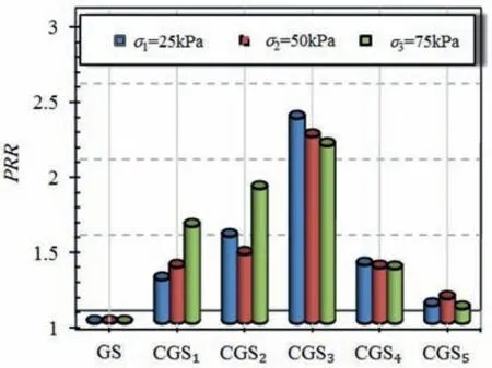
Fig.17. PRR values for different transverse members.
(3) The CGS reinforcement increased the pullout resistance compared to the GS, which was higher for normal stresses.This result is due to the fact that the behavior of the pullout resistance changes from frictional to frictionalpassive when one transverse member is used. For both the GS and the CGS1, the displacement required for the full mobilization of the pullout force under all normal stresses was 16-22 mm. In addition, for the CGS1, the maximum pullout force was obtained at a higher displacement than that of the GS.
(4) The maximum pullout bearing stress(σbmax)calculated from the pullout results concurs well with the punching shear failure mechanism under the lower normal stress.The height of the transverse member and the normal stress play a vital role in predicting the bearing pullout resistance. With an increase in the height of the transverse members and the normal stress, the difference between theoretical and experimental results increased and decreased, respectively.The best agreement was achieved at the height of 50 mm and the normal stress of 25 kPa.
(5) Adding the transverse member is one of the best options for MSEW when there are space constraints. The highest increase in the pullout resistance compared to the GS for all normal stresses(135%,123%,and 117%for normal stresses of 25 kPa,50 kPa and 75 kPa,respectively)was obtained for the CGS3. With an increase in the number of the transverse members to more than three(Tn>3),the pullout resistance decreased because of the interference between various transverse members. In general, using three transverse members increased the maximum pullout resistance by 198.5% and 48.5%, respectively, compared to the SS and the SSR for the normal stress of 25 kPa, and by 158% and 50.8%,respectively, for higher normal stresses on average. This result shows that using the CGS3reinforcement needs at least 55.5%, 63%, and 33.3% smaller length compared to the GS, the SS, and the SSR, respectively.
(6) The experimental results show that the domains of interference between various transverse members can be classified into three zones,i.e.Zone I:block failure(S/H<4),Zone II:interference failure(46.6 or 10).The amount of interference between different transverse members is defined as the interference factor (IF), which depends on the S/H ratio and the interference coefficients ζ and λ. The suggested equation for predicting the bearing resistance in terms of IF,ζ,and λ may help geotechnical engineers in the preliminary assessment of the internal stability of MSEW.
Declaration of competing interest
The authors declare that they have no known competing financial interests or personal relationships that could have appeared to influence the work reported in this paper.
 Journal of Rock Mechanics and Geotechnical Engineering2021年5期
- Journal of Rock Mechanics and Geotechnical Engineering的其它文章
- Surface characteristics analysis of fractures induced by supercritical CO2 and water through three-dimensional scanning and scanning electron micrography
- Prediction of fracture and dilatancy in granite using acoustic emission signal cloud
- Hysteresis in the ultrasonic parameters of saturated sandstone during freezing and thawing and correlations with unfrozen water content
- Coupled Eulerian-Lagrangian simulation of a modified direct shear apparatus for the measurement of residual shear strengths
- A novel true triaxial test system for microwave-induced fracturing of hard rocks
- Hydromechanical behavior of unsaturated expansive clay under repetitive loading
