Better Platooning toward Autonomous Driving: Inter-Vehicle Communications with Directional Antenna
Xiaoyan Wang,Diquan Wang,Nobuhiro Ariyasu,Masahiro Umehira
1 Graduate School of Science and Engineering,Ibaraki University,Hitachi 316-8511,Japan
2 Japan Hi-Think Corporation,Kyoto 600-8815,Japan
3 Hitachi Automotive Systems,Ltd.,Hitachinaka 312-8503,Japan
Abstract: Recently,in the researches on vehicular Internet-of-Things(IoT),platooning have received lots of attentions due to its potential to improve the fuel efficiency and driving experience.Platoon is a group of vehicles that act as smart agents,they travel collaboratively by following the leading human-driven vehicle.A vehicle in the platoon utilizes radar and wireless communication to share important information to other vehicles in the same platoon such as speed and acceleration,to realize the safe and efficient driving.The quality of wireless communication is of great importance to manage and maintain the platoons.However,in a scenario that a large number of vehicles exist,communication delay and packet loss caused by channel congestion may endanger the safe intervehicle distance.In this paper,we introduce intervehicle communication with directional antenna into platooning.By extensive simulations,we evaluate the packet delay and inter-vehicle distance in both normal driving and braking scenarios,and verify the usefulness of directional antenna in platooning for vehicular IoT.
Keywords: vehicular IoT; inter-vehicle communications;directional antenna;platoon safety
I.INTRODUCTION
Vehicular Internet-of-Things (IoT) are indispensable nowadays,and would become an integral part of our lives.Vehicular IoT may bring many benefits to humanity,only if a large amount of vehicles could access and share the communication and computing resources efficiently.Otherwise,it would lead to undesired accidents,traffic congestion,energy waste,pollution and significant economic loss in a society.Obviously,ultra-low latency and reliable Vehicular-to-Vehicular(V2V)communications are the key for most of the future autonomous driving and intelligent transport systems(ITS).
With the help of V2V communications,a great number of vehicular applications have been proposed by the research community for vehicular IoT [1–5].Platooning is a type of collaborative driving system,which is considered as the first practical step of autonomous driving.In platooning,a group of vehicles act as smart agents,they drive together with an extremely small inter-vehicle distance.Specifically,the leading vehicle (i.e.,leader) is driving by human driver,while the other vehicles(i.e.,followers)follow autonomously and collaboratively.Platooning is considered to be applicable and helpful in highway scenarios for logistics.Thanks to the small inter-vehicle distances,platooning is expected to significantly improve the traffic flow and reduce the fuel consumption.In addition,it may potentially improve the safety,since it is assumed that a mechanical fault is less likely to happen compared to human errors.Last but not least,it could reduce the amount of time in driving or enable a less stressful driving experience,since the vehicle is driven by the control system.
The realization of platooning requires various technologies,e.g.,control systems,sensing techniques,wireless communications,etc.In this article,we focus on V2V communications in platooning,whose quality is essential for maintaining close and safe intervehicle distances.As we know,only using the sensorbased information is not possible to reduce the intervehicle distance to a value small enough for platooning.Sharing the dynamics among the vehicles in platoon in real time by exploiting wireless communications,could lead to a significant improvement on system’s reactivity.Two kinds of communication technologies are investigated in platooning,IEEE 802.11p based technology and Cellular Vehicle-to-Everything(C-V2X) based technology,whose details will be introduced in Section 3.2.Realizing low packet loss ratio and latency in platooning are very challenging due to the requirement of highly frequent V2V communications.In a crowded highway scenario,poor communication performance may endanger the safe intervehicle distance,and lead to the car crashes.
In this paper,we focus on the V2V communications in platooning,and investigate if and how the directional antenna would improve its quality.We provide an analysis of the relationship between platoon’s safety and its communication quality,and find that the only factor that affects the platoon’s safety is the beacon delay.Since the beacon delay is closely related to the packet loss rate,we propose to utilize directional antenna to reduce the interference of interplatoon communications.To the best of our knowledge,we are the first to address the intra-platoon communications with directional antenna.To validate its performance,different from the previous work,we consider both the normal driving scenario and braking scenario in the evaluations.The IEEE 802.11p protocol for low layers and IEEE 1609 protocol for high layers are adopted in the simulations.We provide extensive evaluation results on both the communication performance and platoon safety.Specifically,we compare the omnidirectional and directional antennas in terms of packet delay and inter-vehicle distance variance under different traffic loads,and find interestingly that the directional antenna benefits platooning more in small beacon interval and high vehicle density scenarios.
The rest of the paper is organized as follows.In Section II we introduce the related work.In Section III we present the basic and preliminaries for platooning.In Section IV we provide basic evaluation results and analysis for platooning on both normal driving and braking scenarios.In Section V we investigate the possibility and effectiveness by introducing directional antenna in platooning.Finally,we draw the conclusion in Section VI.
II.RELATED WORK
2.1 Intra-platoon Communications
2.1.1 IEEE 802.11p based Approaches
IEEE 802.11p standard has been mainly considered as the communication technology for platooning.In[6],Jonssonet al.proposed a master vehicle based beacon dissemination scheme for platooning,with the purpose of minimizing the collision and maximizing the transmission coverage.In[7],Ucaret al.proposed an IEEE 802.11p and visible light communication based hybrid security protocol for platoon communication,with the goal of ensuring platoon stability and securing platoon maneuvers.In [8],Yuet al.proposed an analytical model to assess the communication property in a single platoon scenario by utilizing Markov process and M/G/1/K queuing theory.Anet al.proposed a cooperative lane change protocol for platooning,by considering the impact of V2V communication delay in[9].In [10],Shenet al.investigated dynamic platoon dispersion models which could capture the variability of traffic flow in a cross-sectional traffic detection environment.In [11],Baladoret al.proposed a media access control protocol for platoons,which is able to transmit beacons within the required time constraints,but with a higher reliability level than IEEE 802.11p.Finally,using directional antenna in platooning have been addressed in the following two works.In [12],Tanket al.discussed the impacts of multipath fading and interference from other vehicles on vehicle-to-vehicle communications.They developed a statistical model for vehicle-to-vehicle radio channel applicable for platooning.And in [13],Leet al.proposed to use an additional antennas for communication between platoon members and a deterministic distributed scheduling scheme together with dynamic switching of antenna beams.
2.1.2 C-V2X based approaches
Recently,C-V2X based V2V communications have also been considered in supporting the delivery of beacon in platooning.Yuet al.evaluated the performance of LTE-Vechicle based V2V platooning communication,and showed that LTE-Vehicle system is unable to support the highest degree of platooning automation under shadowing effects[14].In[15],Meiet al.proposed to jointly optimize the radio resource allocation in LTE-V2V network for the beacon transmission and control parameters of vehicle,in order to minimize the tracking error while guaranteeing the reliability and stability of a platoon.In [16],Campoloet al.investigated the potential of LTE device-to-device (D2D)communications for data dissemination in the platoon.However,due to the requirements of additional signaling,the large latency issue in C-V2X based platooning is still an open research issue.
2.1.3 Field Tests
Besides the theoretical researches,great efforts on platooning experiments have been paid since the last decade.The most famous platooning related project is California PATH (Partners for Advanced Transportation Technology)[17].It worked on the development of CACC system for heavy trucks in collaboration with the Volvo Group since 2015.Some other pioneer work,such as the EU sponsored program ASRTRE[18]and German national project KONVOI [19],deployed platoons by trucks on highway.In these programs,the platoon drove at speed of 90 km/h with the inter-vehicle distance 6~10 m.Another early representative project in Japan called Energy ITS[20]implemented automated truck platooning system and evaluated its CO2 emission reduction performance.Recently,from 2017,EU launched two platoon related projects.One is CONCORDA (Connected Corridor for Driving Automation) project with overall budget 20 million euros [21].It had been working towards the preparation of European motorways for automated driving and high-density truck platooning.The tests were conducted in Netherlands,Belgium,France,Germany,and Spain,with the purpose of analyzing the interoperability of technologies enabling V2X communication under real traffic conditions.Another is ENSEMBLE(ENabling SafE Multi-Brand platooning for Europe)project with overall budget 26.05 million euros [22].It aimed at paving the way for the adoption of multi-brand truck platooning in Europe to improve fuel economy,traffic safety and throughput.The experiments were conducted by driving six differently branded trucks in one(or more)platoon(s)under real world traffic conditions across national borders.
2.2 Inter-platoon Communications
Only limited work investigated the communication performance in scenario with multiple platoons.In[23],Segataet al.proposed a communication strategy with transmit power control for platooning.They developed a communication strategy by explicitly taking into account the requirements of the controller,exploiting synchronized communication slots as well as transmit power adaptation.Penget al[24]provided a probabilistic performance analysis of distributedcoordination-function-based intra- and inter-platoon communications.Their Numerical results showed that the performance of inter-platoon communications is affected by the transmissions of the first and last vehicles.Wuet alproposed a swarming approach [25]to optimize the one-hop delay of inter-platoon communications in a multi-platoon scenario.In [26],the platoon cooperation in the multi-lane cooperative platoon scenario was studied.In [27],Nardiniet alinvestigated the potential of the recently specified CV2X technology to match the latency and reliability demands of platooning application.
All the previous researches focus on the communication performance of platooning in normal driving scenarios.However,in practice,the safety of platoon is of great importance,and whether the platooning can keep a safe inter-vehicle distance in an emergency situation is still unknown.Furthermore,most the previous work do not take antenna pattern into consideration,and whether the directional antenna could improve the performance of platooning in a real world scenario is still an open issue.
III.PLATOONING
3.1 Control System
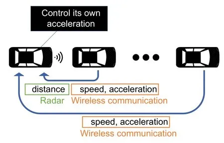
Figure 1.Illustration of CACC system.
In this subsection,we briefly introduce how the followers in the platoon longitudinally control their accelerations to maintain a desired inter-vehicle distance.1Currently,the most widely used control system for vehicles is the Adaptive Cruise Control(ACC).ACC uses a radar to detect the vehicle in front and tries to maintain the speed to a reference speed which is set by the driver.If ACC detects a slower vehicle ahead,it automatically decelerates to maintain a safe inter-vehicle distance.Since ACC requires a large inter-vehicle distance,it cannot be applied in platoon,which needs extremely small spacing between vehicles to reduce the fuel consumption and increase the road throughput.To this end,Cooperative Adaptive Cruise Control(CACC)has been proposed,which utilizes the wireless communication among vehicles to share the information besides radar.The idea of CACC system is illustrated in figure (1).To control the followers in the platoon,the data of the vehicle directly in front,and the data of the leader are both exploited by radar and wireless communications.The control formula of CACC is defined by[28]as

whereui,ui−1andu0are the accelerations of the considered vehicle,the front vehicle and leader respectively,,andare their speeds,xi,xi−1are the positions of the considered vehicle and the front vehicle,li−1is the length of the front vehicle,dis the desired inter-vehicle distance.By Eqn.(1),the acceleration of the follower vehicleiis calculated by using the acceleration,speed of leader vehicle 0,and the acceleration,speed,distance of the vehicle in front,i.e.,i −1.Specifically,the distance information between itself and the vehicle ahead is obtained by radar,and the speed and acceleration information of the vehicle ahead and leader are shared by wireless communications.This control system provides string stability of the platoon with arbitrary inter-vehicle distance.The parametersαiare defined as follows.
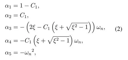
whereC1is a weighting factor for the accelerations between leader and front vehicle,ξis the damping ratio,ωnis the bandwidth of the controller[28].
3.2 IEEE 802.11p Based Vehicular Communications in Platooning
So far,most of the theoretical researches and all the field tests of platooning are based on the IEEE 802.11p standard.Standardization of IEEE 802.11p [29]has been started from 2010,in which the physical layer is OFDM(Orthogonal Frequency Division Multiplexing) based,and the MAC layer is CSMA/CA (Carrier Sense Multiple Access with Collision Avoidance)based.It reserves a dedicated 5.9 GHz band with 7 channels for vehicular communications.To combat the multi-path propagation issue,the OFDM symbol duration is doubled from 4µs to 8µs,and thus the bandwidth decreases from 20 MHz to 10 MHz.Vehicles could communicate directly with other vehicles by using a broadcast MAC address,without the association to an access point.Furthermore,to support higher level vehicular applications,IEEE 1609 standard [30]has been developed,in which higher layer packet format,security primitives,multi-channel operations are defined.Combining lower layers IEEE 802.11p standard with higher layers IEEE 1609 standard,the well-known WAVE(Wireless Access in Vehicular Environments)system is composed.
Next,we explain how the V2V communication works in platooning on top of the WAVE.Recall that to calculate the acceleration of a follower by using CACC,the speed and acceleration of leader and front vehicle are required.This information is shared by V2V beacon transmissions.To reduce the intraplatoon channel contention,the communication inside one platoon is scheduled in a TDMA (Time-Division Multiple Access) fashion.Based on the assumption that each vehicle knows its relative position in the platoon and the number of vehicles in the platoon (i.e.,platoon size),the leader broadcasts the beacon at first,and then-th follower sends the beacon one by one at timing calculated by

whereBIis the desired beacon interval,Trevis the timing of the reception for the beacon from the leader,andNplatoonis the platoon size.nis a number to represent its relative position in the platoon,e.g.,n= 1 for the first follower who is right behind the leader.Note that the last follower in the platoon does not need to send beacon.In the case that the beacon from the leader is missing,each follower except the last one in the platoon sends its beacon automatically at timing by addingBIto its last beacon transmission time.The beacon transmission process repeats for everyBIinterval.Compared with random channel access inside a platoon,this schedule-based process could synchronize the vehicles within a platoon to reduce the channel contention.However,it is obvious that the beacon collisions will still occur among different platoons,since there is no central controller for the beacon transmission scheduling.
3.3 Cellular-V2X Based Vehicular Communications in Platooning
Recently,C-V2X technology [31]has been proposed to optimize the D2D communications in vehicular networks.And utilizing C-V2X in platooning has been presented and discussed in 3GPP Release 15[32].Different from the IEEE 802.11p based approaches,in CV2X based platooning,the spectral resources are allocated by eNodeB(Evolved Node B).In order to transmit,a leader or follower in the platoon must be allocated a number of resource blocks (RBs) which depends on the beacon size and the modulation/coding schemes selected for the transmission.
Specifically,each channel with 10 MHz is divided into subframes with 1 ms,and a group of RBs in the same subframe can be used for both signaling and data transmissions.For each beacon transmission,the leader or follower in the platoon has to request a transmission grant to eNodeB by using random access mechanism.The delay between the request and the reception of the actual data transmission is unavoidable,and in the best case,it lasts 15 ms[27].Therefore,by utilizing the resource allocation by eNodeB,the collision avoidance can be guaranteed but the additional signaling overhead is non-negligible.This overhead might be reduced by SPS ( Semi-Persistent Scheduling),in which eNodeB can reserve subchannels for the periodic transmissions of a vehicle.However,SPS is unable to accommodate the time-varying transmission needs of the vehicles,both from application and resource-allocation perspectives [27].In conclusion,C-V2X based platooning is with great potential,but it still needs substantial improvement.
IV.BASIC EVALUATIONS ON NORMAL DRIVING AND BRAKING SCENARIOS
4.1 Simulation Environment and Engine Model
In this research,we use simulator PLEXE[33]to evaluate the platooning in both normal driving and braking scenarios.PLEXE combines the vehicular network simulator Veins[34]and road traffic simulator SUMO[35].Each vehicle in the PLEXE is associated with an IEEE 802.11p and IEEE 1609 network stack to perform V2V communications.The V2V communications are performed only on CCH (Control Channel),and 6 Mbps bitrate is used which is the optimal one for vehicular safety applications.The beacons with size 200 Byte are transmitted by a static transmit power of 10 mW.In the simulation,we vary the beacon interval at range 20~70 ms,since the maximum beacon interval for CACC is 100 ms[36].Main parameters for the simulations,in terms of V2V communications,CACC controller and platoon scenario,are summarized in Table 1.
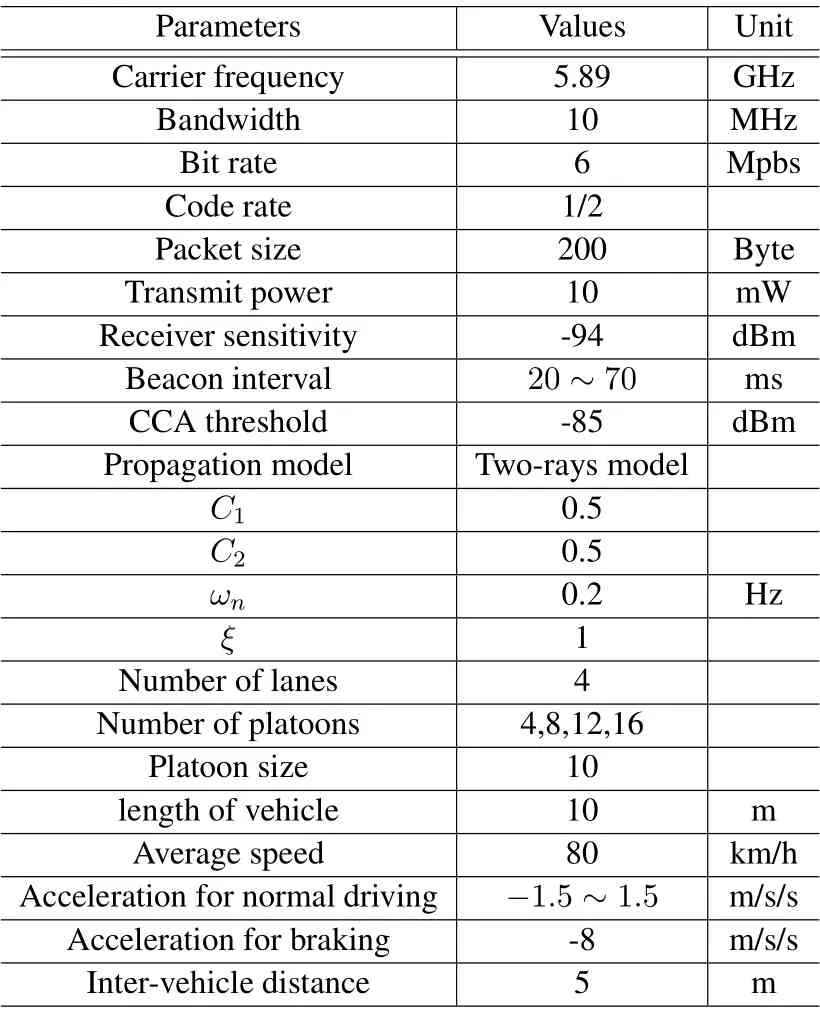
Table 1.Main parameters for simulations.
To accurately evaluate the inter-vehicle distance variance for platooning,we utilize the realistic engine model[33]in the simulations.Different from the widely used first order lag model that assumes symmetric acceleration and braking dynamics,the adopted model takes into account the physical limits of vehicles.Specifically,the acceleration of the vehicle ismodeled as

whereλis an inertia factor,mis the mass of vehicle,τ()is a speeddepend lag time,FuandFFare the effective traction and friction forces respectively.The friction forceFFis defined as[37]

whereFAis the air resistance,FRis the rolling resistance,andFGis the gravitational force.Effective traction forceFuis defined as eitherFengwhen it is a propelling force,or−Fbrakeif it is a braking force.Specifically,Fengis defined as a function of the engine speed[38]as

whereηis the engine efficiency,Peng(Neng)is the engine power which is a function of the engine speedNeng,andis the speed of vehicle.AndFbrakeis defined as

whereµis a friction factor between the tires and road,gis the gravitational acceleration,uis the control input.The lag timeτ() is defined as either the sum of fuel injection time,combustion time and transport delay when it is an actuation lag for the engine,or a constant value (e.g.,200 ms) when it is an actuation lag for the braking system.For the detailed physical meaning and explanation of the realistic engine model,please refer to[33].
We simulate a 4-lane highway scenario with platoon size of 10 vehicles.We consider a dense vehicular network by varying the number of platoons at 4,8,12 and 16,to verify if the platooning could drive safely at congested highways at rush hours.The desired intervehicle distances for the followers are set at typical value 5 m,and the average speeds of vehicles are set at 80 km/h.We consider two types of scenarios in the simulations,i.e.,normal driving scenarioandbraking scenario.In the normal driving scenario,each platoon leader will change its speed in a sinusoidal fashion,continuously accelerating and decelerating,with a small acceleration in range−1.5~1.5 m/s/s.And in the braking scenario,the leader will drive at a constant speed and brake down to a complete stop.The deceleration is set at 8 m/s/s.
Obviously,the traffic volume grows linearly as the number of platoon increases.For instance,the number of beacons reaches 8000 per second when there are 20 platoons drive in the road.It is expected that large number of them will be lost due to collisions,since single CCH is used for V2V communication for platooning.However,the traffic volume could be suppressed significantly when we enlarge the beacon interval.For instance,the traffic volume could decrease from 8000 to 2000 per second,if we enlarge the beacon interval from 20 ms to 80 ms.Unfortunately,the control law of CACC requires high frequency information updating from both the leader and the vehicle in front.Therefore,the generation of high traffic volume for platooning is inevitable in practice,and how to deal with this problem is of great importance.
4.2 V2V Communication Performance in Platooning
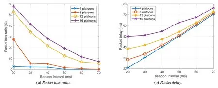
Figure 2.V2V communication performance at different number of platoons.
In this subsection,we evaluate the V2V communication performance of platooning in a normal driving scenario.As discussed in the previous subsection,in a congested highway,the traffic volume due to the platoons’ frequent beacon transmissions is extremely high.Here,we quantitatively evaluate the average packet loss ratio of beacon transmissions at different number of platoons.Notice that the beacons include both the beacons that broadcasted by the leader and the beacons transmitted from the vehicle in front.The simulation results are given in figure (2a).It is obvious that when the density of vehicles is low,the packet loss ratio is under 3%regardless of the values of beacon intervals.When the number of platoon increases to 8,however,the packet loss ratio suddenly grows to nearly 30%for 20 ms beacon interval case.Regarding the scenarios that the numbers of platoons are 12 and 16,the packet loss ratios increase significantly at all the beacon intervals.Specifically,for the case of 20 ms beacon interval,the packet loss is more than 50%.
Next,we show the evaluation result of packet delay by figure (2b).Here,the packet delay is defined as the interval between the current received beacon and the previous received beacon from a particular vehicle.Typically,the packet delay for platooning is required to be lower than 100 ms [11,23,27].Notice that if we neglect the signal propagation delay,the packet delay equals to beacon interval if there is no packet loss.Therefore,the packet delay should be equal to or larger than the beacon interval.We can confirm that the packet delay almost equals the beacon interval,when the density of vehicles is low.This result is expected based on the packet loss result shown in figure(2a).Regarding the result for 8-platoons scenario,the packet delay increases,especially when the beacon interval is set at 20 ms.As the density of vehicle further grows,the packet delay increases significantly.We can observe that the packet delay reaches over 50 ms,when the platoon uses 20 ms beacon intervals.The high packet delay would result in stale input information for the CACC,and thus the safe inter-vehicle distance may no longer be maintained.
4.3 Inter-vehicle Distance Evaluation and Analysis
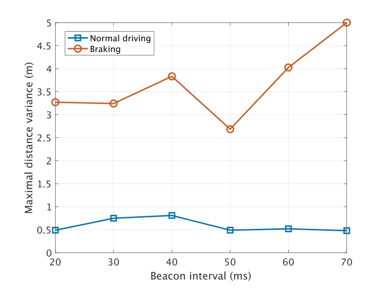
Figure 3.Maximal inter-vehicle distance variance versus beacon interval.
To realize safety platooning,maintaining desired inter-vehicle distance is of great importance.In this subsection,we evaluate the maximum inter-vehicle distance variance of platooning in both normal driving and braking scenarios.The leaders drive in a sinusoidal fashion by continuously changing their speeds in normal driving scenario,and drive at a constant speed and then brake down to a complete stop in braking scenario.To accurately evaluate the variance of inter-vehicle distance,the realistic vehicle model introduced in Section 4.1 is implemented.The evaluation result in terms of maximal inter-vehicle distance variance when the number of platoon is 16 is illustrated in figure(3).We can observe that the maximal distance variance for normal driving scenario is always smaller than 1 m,regardless of the beacon interval.However,in braking scenario,the maximal distance variances increase significantly in all the beacon interval settings.Specifically,when the beacon interval is set to 70 ms,the variance of the inter-vehicle distance reaches 5 m,which means a car crash occurs.
Next,we analyze the main factor that could prevent a collision of vehicles by considering a simple leaderfollower model.We consider the case that two vehicles drive at the same speedv0with distanced.When the leader brakes,to avoid a car crash,the following condition must be satisfied.

whereais the deceleration,τis the packet delay in which the leader informs the follower to brake,tis time andTis time for the leader to completely stop.By replacingt=Tandinto Eqn.(8),we can derive the condition to prevent a car crash as

From Eqn.(9) we can find that when the initial speedv0and inter-vehicle distancedare given,the only factor that affects the collision of vehicles is the packet delayτ.Theoretically,two vehicles will not collide with each other as long as the packet delay satisfies Eqn.(9).For instance,if the inter-vehicle distance is 5 m,the maximum allowable delay is 225 ms when the speed before braking is 80 km/h.And as expected,the allowable delay gradually decreases as the vehicle speed increases.
To verify this analysis result,we perform a simulation with platoon size 16.We show an example of the relationship between relative speed and beacon received timing sequence in figure(4).In this example,the leader brakes at timing 5 s,and the blue line shows the relative speed of a follower.We can find that the only factor that affects the changing of relative speed is the timing of the first received beacon after the braking.Specifically,the relative speed reaches 0.53 m/s at timing 5.5 s when the first beacon is received at timing 5.09 s(figure(4a)),and this value could reduce to 0.24 m/s at timing 5.5 s if the first beacon is received at 5.045 s (figure (4b)).Notice that the missing beacon at timing 5.25 s in figure(4b)does not even affect the relative speed.This result is expected based on our analysis.Therefore,we can conclude that the idea that dynamically adjusting the beacon interval depending on the acceleration of the platoons cannot improve the safety.Since changing the beacon interval after the braking is too late to diminish the variance of relative speed.To guarantee the safe inter-vehicle distance,we have to consider the worst case,i.e.,braking scenario,all the time,and try to reduce the packet delay in the condition of huge traffic volume.
V.PLATOONING WITH DIRECTIONAL ANTENNA
5.1 Antenna Pattern
As we known,the directional antenna has highly directive radiation pattern along a particular direction.It could assist us to control the network traffic in particular areas.We could control the antenna gain in different angles to reduce the interference from the platoons that driving in other lanes.To this end,we adopt array antenna that mounted on a vehicle to realize the desired directivity.The antenna gains of an array antenna with uniformly spaced elements are calculated by the following equations[39].

whereaiis the weight of elementi,dis the element spacing,φis the angle,andkis the wave number which equals.In the simulations,we use omnidirectional antenna shown in figure(5a)and array antenna with 10 elements that illustrated in figure (5b),whose half-power beam-width is 19.2◦.Both types of antennas are set to behave identically for transmitting and receiving.
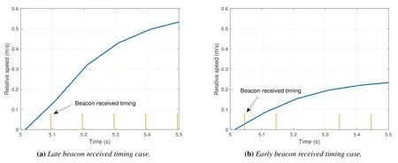
Figure 4.The relationship between relative speed and beacon received timing.
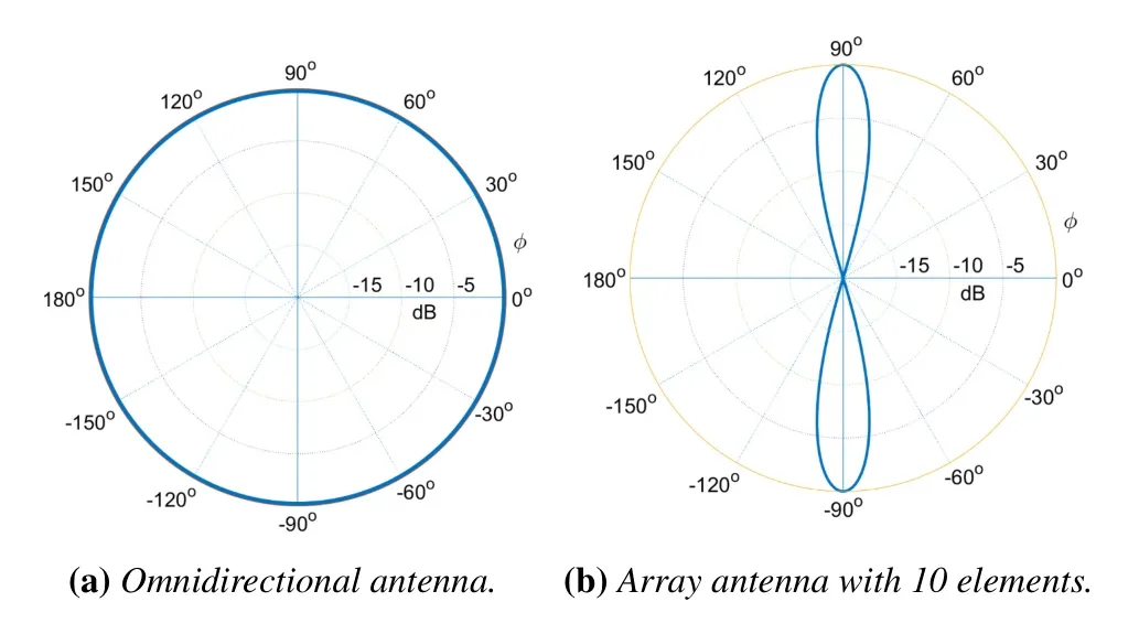
Figure 5.Antenna pattern.
5.2 Evaluations on Packet Delay
Firstly,we compare the omnidirectional antenna and directional antenna in terms of average packet delay.As illustrated in figure (6),in small beacon interval cases,e.g.,20 and 30 ms,the directional antenna outperforms the omnidirectional one in terms of packet delay,especially when the density of vehicles is large.For instance,there is an approximately 24%improvement on packet delay when the number of platoons and beacon interval equal 16 and 20 ms,respectively.However,as the beacon interval increases,the performance gain becomes smaller gradually.And finally,when the beacon interval increases to 70 ms,the packet delay of directional antenna becomes slightly worse than that of omnidirectional one.
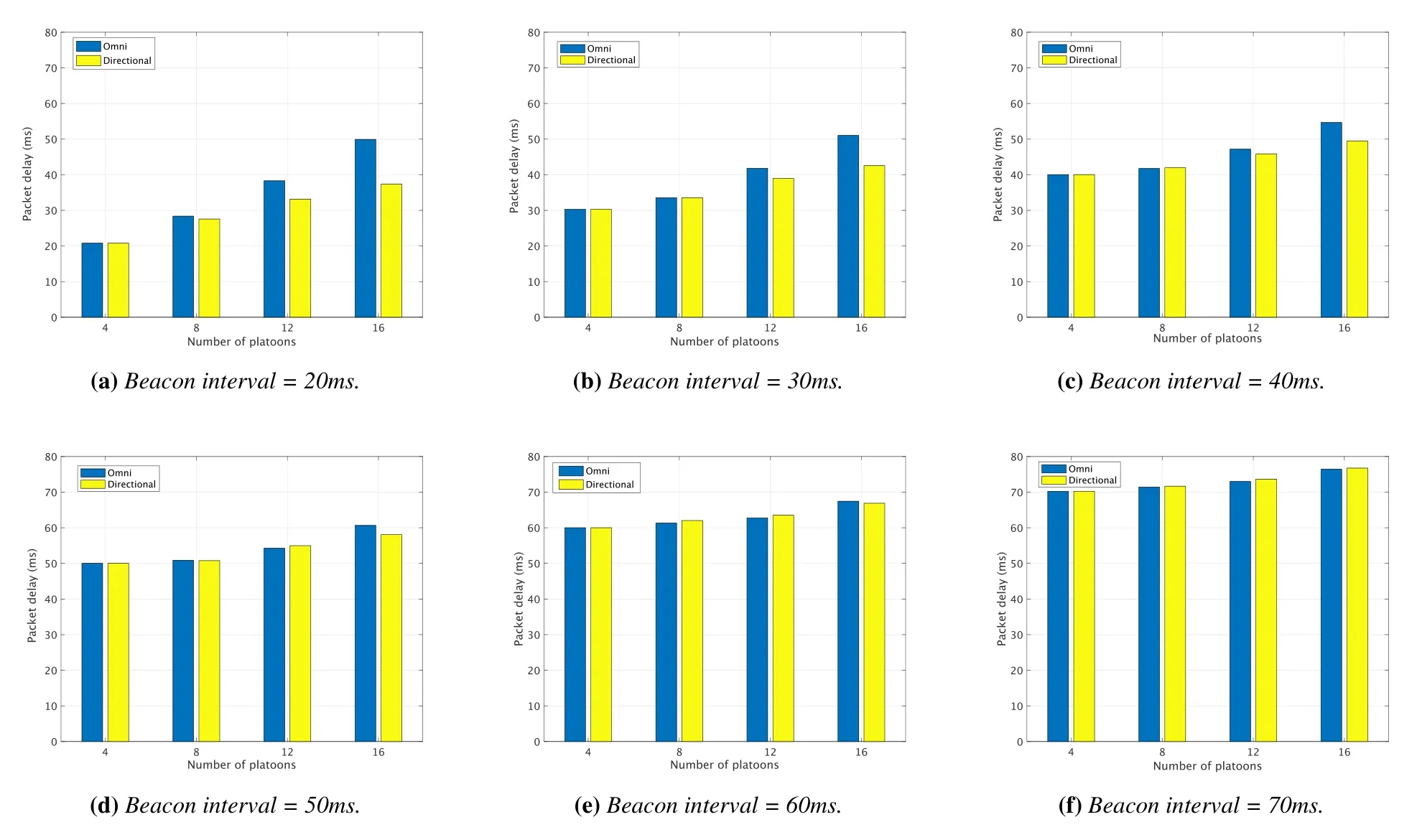
Figure 6.Average packet delay at different beacon intervals.
This results imply that bring directional antenna into platoon has both advantages and disadvantages.Regarding the upside,as mentioned previously,the interference range could be narrowed down.Specifically,the interference of beacons transmitted from other platoons in neighbour lanes is significantly reduced,which leads to the improvement of packet delay.However,for the downside,the probability of the occurrence of hidden terminal problem increases due to the utilization of directional antenna.To facilitate better understanding,we use an example scenario shown in figure (7) to explain this issue.We consider a 2-platoons scenario,the first platoon consists of leader A and follower B,the second platoon consists of leader C and follower D.As shown in figure(7a),leader A is transmitting beacon to follower B.Assume that at the same time,leader C also wants to transmit beacon to follower D.When the omnidirectional antenna is used,leader C is inside the transmission range of leader A,therefore leader C can sense the channel is busy and backoff its transmission to avoid packet collision.However as shown in figure (7b),leader C is outside the transmission range of leader A when the directional antenna is utilized.In this case,leader C senses the channel and finds the channel is idle.Therefore,leaders A and C will transmit their beacons to followers B and D at the same time,respectively.As the results,packet collisions occur at followers B and D since the leaders A and C are hidden with each other.By taking into account both the upside and downside of utilizing directional antenna in platooning,we found that in high traffic volume scenario,the merit of directional antenna,i.e.,the reduction of interference range,dominates.However,when the density of vehicles is low,the negative effect brought from directional antenna,i.e.,hidden terminal problem,is comparatively large and makes the performance even worse compared with omnidirectional antenna.
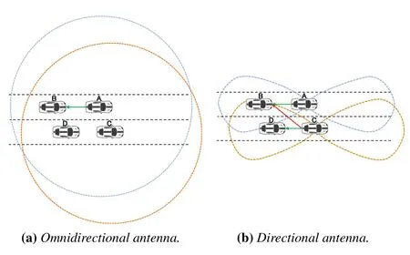
Figure 7.Illustration of hidden terminal problem by using directional antenna.
To further confirm this result,we show the Complementary Cumulative Distribution Function(CCDF)of packet delay in figure(8)when the number of platoon is 16.Similar to the results given in figure (6),when the beacon intervals are 20 and 30 ms,i.e.,traffic volume is large,platooning with directional antenna significantly outperforms the one with omnidirectional antenna.When the beacon interval becomes large,i.e.,the traffic volume decreases,the directional antenna still performs better in terms of the probability of small packet delay.However,there exist some rare cases that the directional antenna will result in extremely large packet delay,which is highly unexpected.
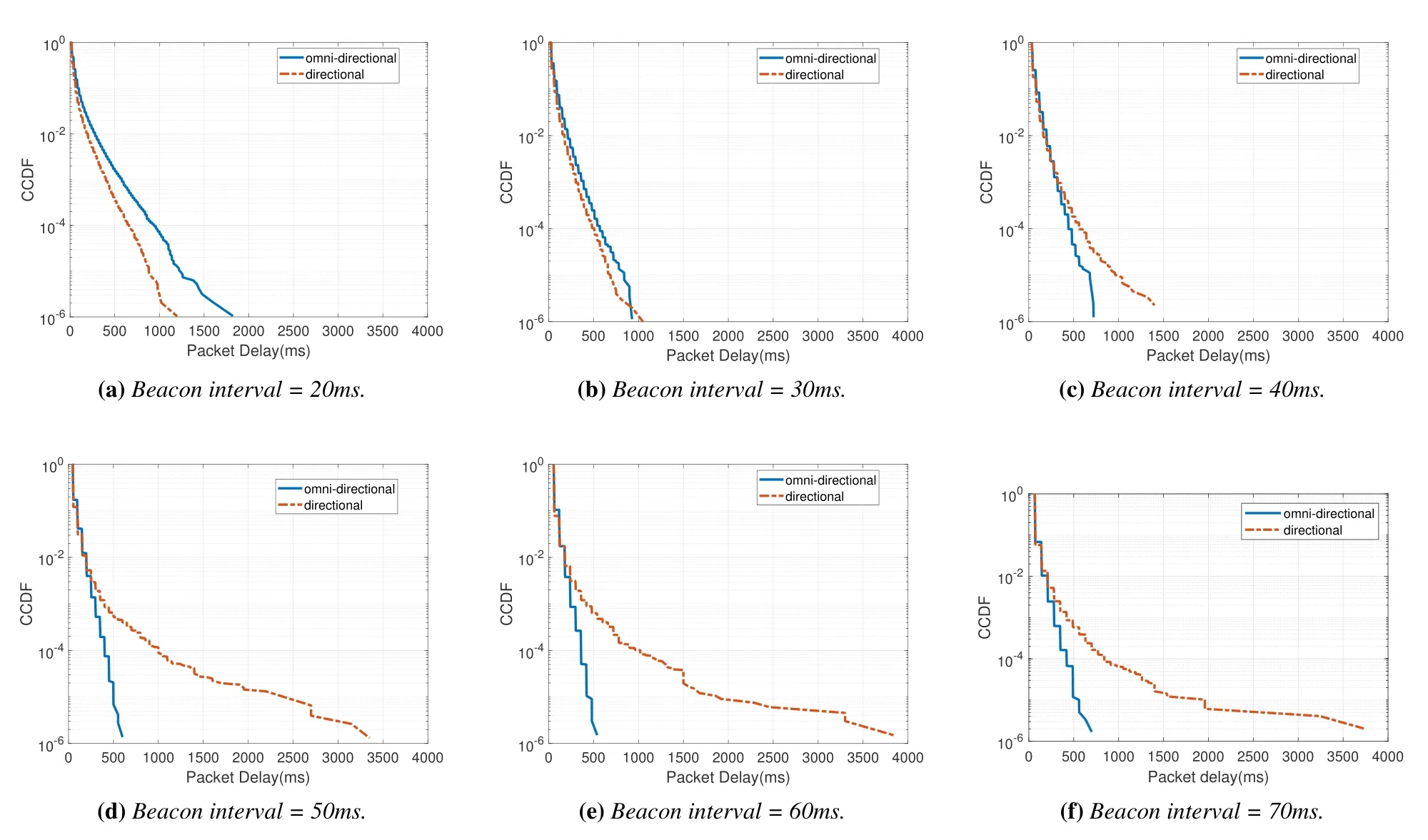
Figure 8.CCDF of packet delay with different beacon intervals(number of platoons=16).
5.3 Evaluations on Inter-Vehicle Distance Variances
Finally,we show the CCDF of inter-vehicle distance variations in figure (9) when the number of platoons is 16.Based on the evaluation results,we can observe that the variations of inter-vehicle distance are in the range of[−2,5]m.Here,the negative value means the distance between two vehicles gets farther,and positive value means the distance gets closer.Since the original inter-vehicle distance is 5 m,the variation of distance with 5 m means the car crash occurs.From figure (9),we can observe that when the beacon intervals are small,i.e.,below 40 ms,platooning with directional antenna outperforms the one with omnidirectional antenna.For instance,in the 20 ms beacon interval case,the probability of inter-vehicle distance variance below 0.5 m increases approximately 12% by using directional antenna.However,as the beacon interval increases,the benefits of directional antenna gradually disappear.The reason is that the benefits of interference range reduction is remarkable only when the traffic volume is large.When the traffic volume is small,this benefit is almost offset by the downside brought from the hidden terminal problem of directional antenna.This results is coincident with the results of packet delay,which proves our analysis in Subsection 4.3.
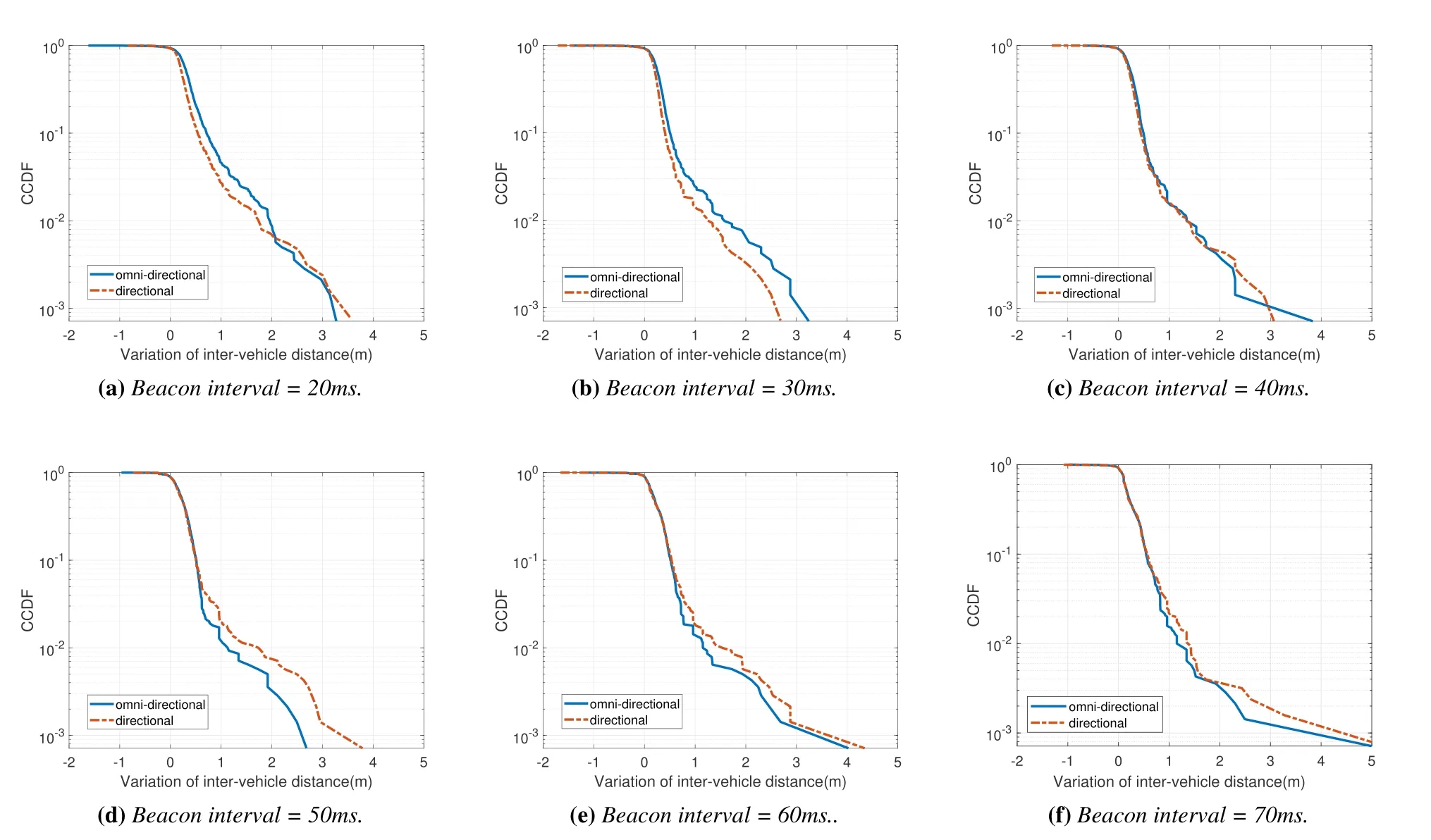
Figure 9.CCDF of inter-vehicle distance variances with different beacon intervals(number of platoons=16).
VI.CONCLUSIONS
In this paper,we introduce directional antenna into platooning for future vehicular IoT systems,and evaluate its V2V communication performance and safety in both normal driving and braking scenarios.Through our analysis,we found that the only factor that affects the safe platoon driving is the packet delay.We perform extensive simulations,by taking consideration of the vehicle following model of CACC and realistic vehicle engine model.The interesting results we found is that the directional antenna benefits platooning more in the short beacon interval and high vehicle density scenarios.
For the future work,firstly,we would consider the scheme that using omnidirectional antenna to sense the channel but directional antenna to transmit.By using different antenna patterns to perform sensing and transmission respectively,it is expected to alleviate the negative impacts of hidden terminals.Secondly,it would be interesting to perform a systematical evaluation of platooning in different patterns of curved roads,and compare with adaptive beam forming.In the current work,we only consider the straight road with different number of lanes.However,the performance of directional antenna might degrade if the platoon is driving in a curved road.In that case,it might be required to perform adaptive beam forming so that the leader and followers in the platoon can keep in contact all the time.Third,it is necessary to optimize the parameters of platooning,such as beacon interval,transmitting power,according to different traffic loads.It would be promising to exploit the recent advancement of reinforcement learning to let the leader of platoon acts as a smart agent,who monitors the surrounding environment and learns the optimal parameters dynamically during the driving.
VII.ACKNOWLEDGEMENT
This research was supported by Grant-in-Aid for Scientific Research(C)(20K11764),the Telecommunications Advancement Foundation and ROIS NII Open Collaborative Research 21FA01.
- China Communications的其它文章
- Joint Topology Construction and Power Adjustment for UAV Networks: A Deep Reinforcement Learning Based Approach
- V2I Based Environment Perception for Autonomous Vehicles at Intersections
- Machine Learning-Based Radio Access Technology Selection in the Internet of Moving Things
- A Joint Power and Bandwidth Allocation Method Based on Deep Reinforcement Learning for V2V Communications in 5G
- CSI Intelligent Feedback for Massive MIMO Systems in V2I Scenarios
- Reinforcement Learning Based Dynamic Spectrum Access in Cognitive Internet of Vehicles

