Joint Topology Construction and Power Adjustment for UAV Networks: A Deep Reinforcement Learning Based Approach
Wenjun,Xu,Huangchun Lei,Jin Shang
1 The Key Laboratory of Universal Wireless Communications,Ministry of Education,Beijing University of Posts and Telecommunications,Beijing,China
2 Frontier Research Center,the Peng Cheng Laboratory,Shenzhen,China
Abstract: In this paper,we investigate a backhaul framework jointly considering topology construction and power adjustment for self-organizing UAV networks.To enhance the backhaul rate with limited information exchange and avoid malicious power competition,we propose a deep reinforcement learning (DRL) based method to construct the backhaul framework where each UAV distributedly makes decisions.First,we decompose the backhaul framework into three submodules,i.e.,transmission target selection(TS),total power control(PC),and multi-channel power allocation (PA).Then,the three submodules are solved by heterogeneous DRL algorithms with tailored rewards to regulate UAVs’behaviors.In particular,TS is solved by deep-Q learning to construct topology with less relay and guarantee the backhaul rate.PC and PA are solved by deep deterministic policy gradient to match the traffic requirement with proper finegrained transmission power.As a result,the malicious power competition is alleviated,and the backhaul rate is further enhanced.Simulation results show that the proposed framework effectively achieves system-level and all-around performance gain compared with DQL and max-min method,i.e.,higher backhaul rate,lower transmission power,and fewer hop.
Keywords: UAV networks; target selection; power control; power allocation; deep reinforcement learning
I.INTRODUCTION
Benefitting from low deployment cost and high flexibility,unmanned aerial vehicle (UAV) networks are promising as a significant reinforcement of 5G wireless communication systems[1–3].In particular,UAV networks serve as collaborative aerial base stations in support of transmission network in various scenarios,such as Internet of Things[4,5],mobile networks[6]and edge computing[7].
An efficient backhaul framework is the cornerstone of UAV networks to enable various transmission tasks.Commonly,two challenges,topology construction[8]and power adjustment [9],are crucial for UAV networks.On the one hand,the fast-changing positions of UAVs require dynamic topology construction.However,the high mobility of UAVs brings difficulties on how to select a transmission target.On the other hand,power adjustment alleviates interference in support of dynamic topologies.But in distributed UAV networks,the lack of timely and global information exchange degrades the performance of interference control.In summary,a well-performed backhaul framework should meet the following two requirements:
Dynamic topology construction:It means UAVs autonomously switch transmission modes between direct and relay transmission to adapt to the fastchanging relative positions.Conversely,in the static topology1[10–14],source UAVs and relay UAVs inactively keep their pre-allocated transmission modes unchanged.The inaction can cause needless relay and congestion.
Distributed and local-information-based (LIB)decision:First,task-driven UAV networks are often self-organizing.Hence,it requires distributed decision[11].Second,LIB decision is usually required since the channel coherence time,which is similar to the lifetime of channel state information(CSI),is usually small2in high mobility scenarios[15–17].In UAV networks,LIB decision means that UAVs immediately make decisions after receiving only local CSI from one-hop neighboring UAVs,and avoids prolonged iteration with multi-UAV feedback.
For overcoming the constraints of the two requirements,it is worthy to construct the backhaul framework by exploiting deep reinforcement learning(DRL)[18],which has blazed a path of solving complex decision-making problem in wireless communication [19–22].DRL is a combination of reinforcement learning (RL) and deep learning (DL).Therein,RL instructs an agent in learning an optimal decision policy by interacting with a dynamic environment,and DL serves as a powerful tool to parametrically model the decision policy.
However,in a distributed and LIB setting,if the backhaul framework is mechanically constructed by DRL,it can cause self-centered behaviors and severe interference.For example,with only local information,each UAV enhances transmission power immoderately to guarantee its own transmission quality.As a result,backhaul rate (BR) is limited by malicious interference.We refer to this phenomenon as malicious power competition(MPC).In summary,the high mobility,two requirements,i.e,distributed and LIB,and MPC form an intricate chain reaction,which constrains the performance of the backhaul framework.
In order to tackle this chain reaction,first,we decompose the backhaul framework into three submodules,i.e.,transmission target selection (TS),power control(PC),and power allocation(PA).Then,we use heterogeneous DRL methods with tailored rewards to tackle them.Specifically,TS is solved by deep Qlearning(DQL)to enhance BR and reduce needless relay.Fine-grained PC and PA are solved by deep deterministic policy gradient (DDPG) to control the interference among UAVs.Therefore,we refer to the proposed framework as decomposed heterogeneous DRL(DHDRL).The advantages of DHDRL are two folds.First,DHDRL enables submodules to meet various requirements.As a result,the synthesis of these submodules achieves system-level and all-around performance gain.Second,this framework decomposes the joint action space into three small action spaces corresponding to the three submodules,which are easy to explore.
1.1 Related Work
We review the researches about TS,PC,and PA as follows:
Non-DRL methods:In[10],the authors use matching method to select relay UAVs and subchannels to improve the satisfaction and fairness for selforganizing UAV networks.They also introduce a class of matching method [11]in similar settings.In [12],the authors optimize relay selection and PC by geometric approach in non-orthogonal multiple access networks.These methods are all based on static topology.However,in dynamic topology,it is difficult for these methods to optimize BR due to the varying transmission mode.In addition,these methods require multi-hop CSI exchange or iteration which makes high demand on the lifetime of CSI.
DRL methods:Since DRL learns optimal decision policy from BR feedback,it bypasses the difficulty of the non-DRL methods in directly solving the optimization problem.Based on deep-Q learning (DQL) [23],some researches [24,13,25]execute multi-function decision to enhance transmission rate.They consider some functions including PC,PA,scheduling,and trajectory optimization.Based on actor-critic learning [26],the authors in [14]execute routing and PC to enhance the goodput for delaysensitive applications.In summary,these researches use a single DRL model to jointly select action combinations of all functions aiming at a sole goal.However,in a distributed and LIB setting,this common usage cannot effectively alleviate MPC.Although in[27],the authors use two DQL models to tackle TS and PC separately,it avoids MPC by centralized and global-information-based setting.
Multi-agent DRL methods:UAV networks are typical multi-agent systems.In[28],to enhance transmission rate by optimizing trajectory and PC,each UAV trains its own model assisted by the information from other UAVs.On the contrary,in [29],the authors train a shared DQL model for dynamic power allocation to enhance a weighted sum-rate.Similarly,a shared model is trained by multiple parallel learners[30].If regarding a learner as an agent,the demonstration in[30]is still valuable that multiple learners can explore the different parts of the environment.Meanwhile,since all UAVs have identical status in our settings,a powerful shared model is preferred in the context of large-scale industrial deployment.
1.2 Contribution
In this paper,we research a backhaul framework jointly considering topology construction and power adjustment for UAV networks.Further,we propose a solution framework,namely DHDRL.The main contributions are as follows:
• Considering dynamic topology and traffic,transmission priority,and congestion,we propose DHDRL to construct a distributed and LIB backhaul framework for UAV networks jointly considering topology construction and power adjustment.First,DHDRL decomposes the backhaul framework into three submodules,i.e.,TS,PC,and PA.Then,it tackles the three submodules by leveraging heterogeneous DRL methods and tailored rewards.The results show that DHDRL achieves better system-level and all-around performance than DQL,i.e.,higher BR,lower transmission power and fewer hops.
• In DHDRL,we propose a TS method based on deep Q-learning (DQL).First,we put forward a heuristic approach to refine the relay UAV set.Then,considering BR,transmission power,and transmission mode,we design a tailored reward to guarantee BR and avoid needless relay.
• In DHDRL,we propose fine-grained PC and PA methods based on DDPG.For alleviating MPC,we design tailored rewards to adjust transmission power to the traffic requirement.As a result,the potential of BR is further released.
The rest of this paper is organized as follows.Section II establishes the system model and formulates the optimization problem.Section III presents DQLbased TS and DDPG-based PC and PA first,and then the joint DHDRL framework.Section IV presents the simulation results.Finally,Section V concludes the paper.
Notations: Vectors (Matrices) are defined as boldface lower case letters(capital letters).E(·)is the expectation operator.(·)Tis the transpose operator.|·|is the 2-norm of a vector.The notations of environment variables are summarized in Table 1.
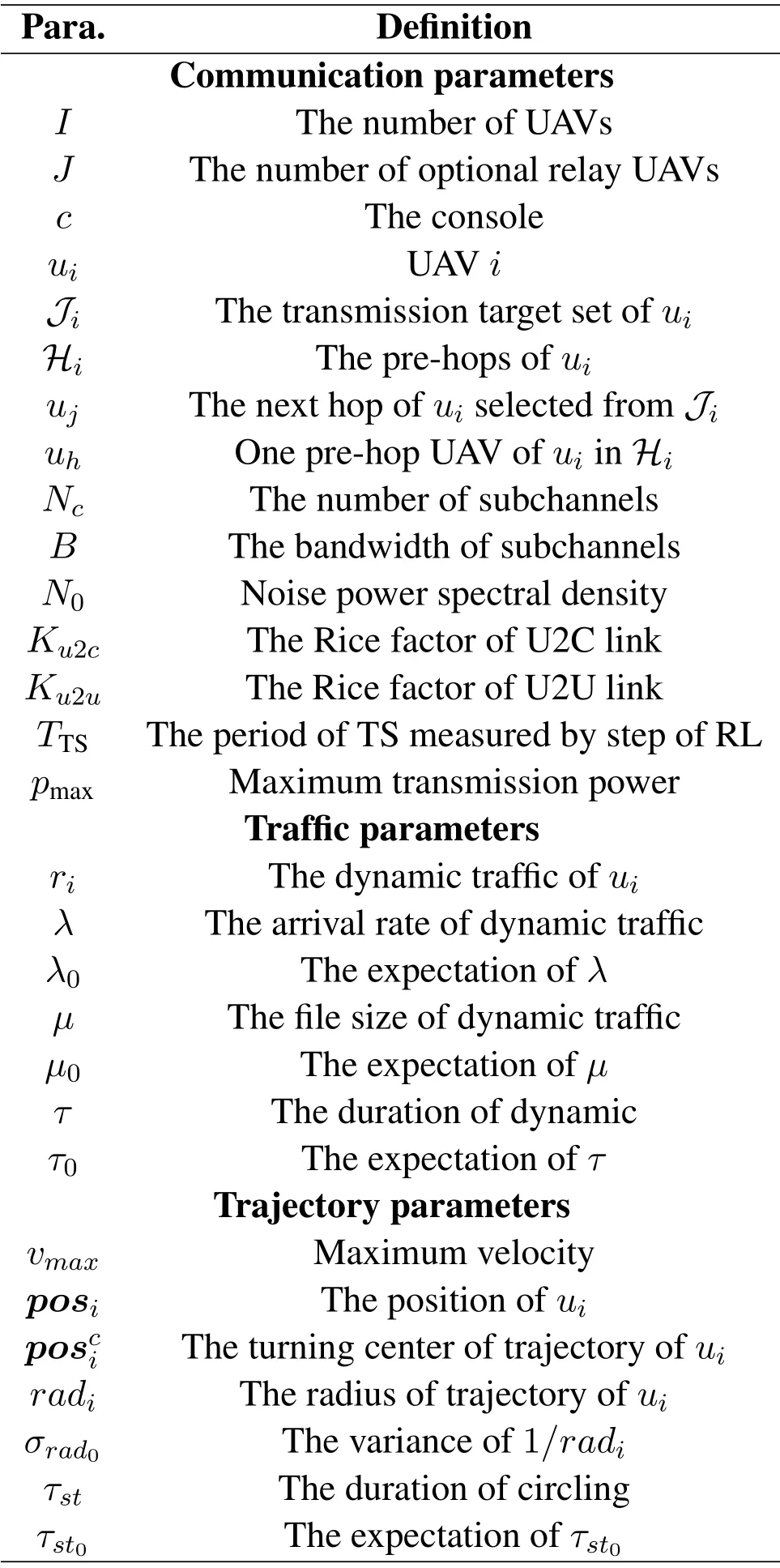
Table 1.The definitions of environment parameters.
II.SYSTEM MODEL
We consider the scenario as shown in figure 1.The UAV network executes regional monitoring or emergency response with a certain kind of trajectories,where each UAV transmits dynamic traffic to a console.Aiming at enhancing BR without dedicated relay UAVs,we propose a collaborative backhaul framework.First,each UAV autonomously executes TS,i.e.,selecting the console for direct connection or selecting another UAV for a relay.Then,each UAV executes PC and PA to transmit its own traffic first and then the relay traffic.Based on DHDRL introduced hereafter,each UAV distributedly executes the three submodules after receiving the local information from one-hop neighboring UAVs.We refer to one transmission round as one step in the context of RL,and the interval between two steps isT.Since TS is less frequent than PC and PA,we assume all UAVs asynchronously execute TS everyTTSsteps and execute PA and PC every step.The relay mode is considered as decode-and-forward.
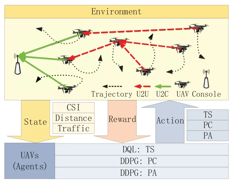
Figure 1.Scenario model.
2.1 Traffic Model
We assume the traffic of UAVs is independent and identically distributed(i.i.d).The arrival rateλobeys poisson distributionλ ~P(λ0) with expectationλ0,and the file sizeµobeys uniform distributionµ ~U(0.5µ0,1.5µ0) with expectationµ0.Therefore,the traffic load of UAViis ˆri=λµ.The duration of ˆrisubjects to exponential distributionτ ~Exp(1/τ0),and turns into steps quantified withTin RL.τ0is the expectation ofτ.ˆriwill be updated in the next step when its duration ends.
2.2 Transmission Model
The backhaul link,transmission priority and variable definition are shown in figure 2.The UAV set is defined asU={u1,...,ui,...,uI}.Iis the number of UAVs.The console is defined asc.The unique selected transmission target,i.e.,the next hop ofui,isujorc.It is selected by DHDRL from the transmission target setis an optional relay UAV selected fromUi−,which meansUexceptui.Jis the cardinality of the relay UAV set.The elements ofJiare selected by a heuristic approach described in Section III.The prehops ofuican be multiple and are defined asHi={u1h,...,uhh,...,uHh|uhhis the pre-hop ofui}.His the number of pre-hops ofui.When a certainuhhis referred,it is simplified asuh.Variables with subscriptj,iandhare corresponding to next hopuj,decision makeruiand pre-hopuh,respectively.SinceJiandHidirectly connect toui,we refer to them as one-hop neighboring UAVs ofui.Hence,the local information exchanges betweenuiand them is within the lifetime of CSI.
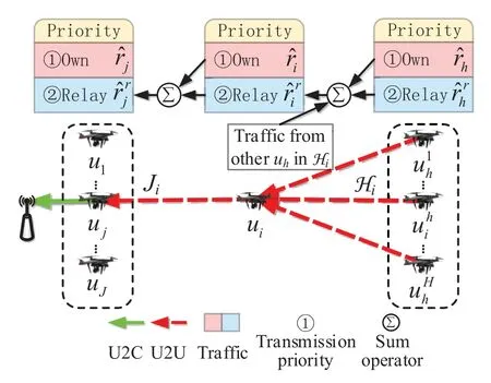
Figure 2.Illustration of backhaul link and transmission priority.In this illustration,ui has multiple pre-hops.For conciseness,ui is the unique pre-hop of uj.
2.2.1 Channel model
We assume all UAVs shareNcsubchannels.The UAV-to-console (U2C) and the UAV-to-UAV (U2U)links [31]are considered as the free-space path loss model[32]with Rician fading [33].The subchannel set is defined asNc={1,...,n,...,Nc},whereNcis the number of subchannels.The channel gains of subchannelnfromuitoc(fromuitouj)is defined as


respectively,wheredui,c(dui,uj)is the Euclidean distance betweenuiandc(uj),fis carrier frequency,andξu2c(ξu2u)is the small scale effect of U2C(U2U)link with the Rice fatorKu2c= 3(Ku2u= 10).hui,c(hui,uj) is the channel gain vector consisting ofhnui,c(hnui,uj)of all subchannels.We assume that CSI is perfectly estimated and Doppler effect is well compensated[10].The signal-to-interference-plus-noise ratio(SINR)of each subchannel of U2C(U2U)link is defined as
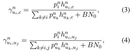
wherepniis the transmission power of subchannelnofui,Bis the bandwidth,andN0is the noise power spectral density.The total transmission power ofuiis defined asThe maximum power is defined aspmax.The total capacityCui,c(Cui,uj) of U2C(U2U)link is defined as
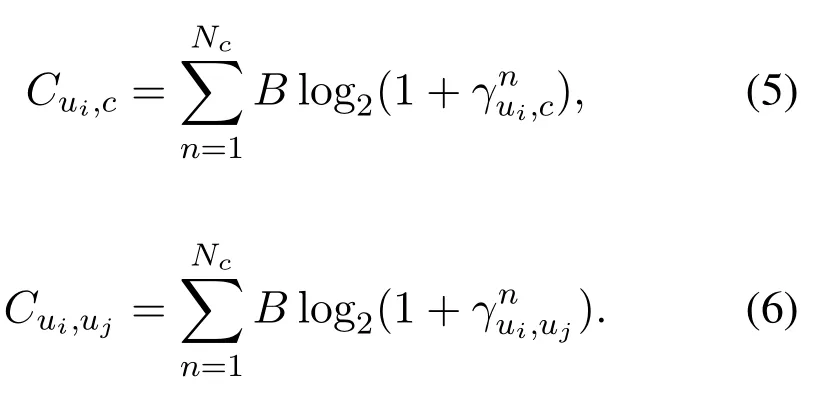
The maximum capacity betweenuiand its target is defined asCi=Cui,uj(Ci=Cui,c) whereuj(c) is the transmission target.
2.2.2 Backhaul Rate model
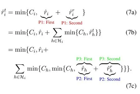
The transmission priority is explained with figure 2.Variables are defined as follows3:: Own traffic requirement ofui.: Total relay traffic requirement ofuifromHiconstrained byCh.: Total traffic requirement ofui,which consists of own trafficand relay trafficri: Actual BR of own traffic ofui.It is the part oftransmitted successfully.rti: Actual BR of total traffic ofui.It is the part of ˆrtitransmitted successfully.: Idle capacity fromuito its transmission target afteruitransmits its own traffic,i.e.,=max{Ci −,0}.
Taking the multi-hop backhaul linkug →uh →ui →cas an example,the total trafficofuican be expanded as Eq.(7).The transmission priority follows three points,which are explained by the red,blue and green notes in Eq.(7),respectively.
• P1.Own traffic is transmitted first:uitransmitsfirst and thenby usingCidlei.
• P2.In relay traffic,own traffic of pre-hops is transmitted first:After transmittingcompletely,uiusesto transmit,which consists of the sum ofandof alluhinHi.In this case,uitransmits the sum offirst and then
• P3.Fairness:Considering congestion and P2,whenis less than the sum of,is used to transmit ˆrh,and is allocated by the proportion of.Whenis greated than the sum ofthe residue ofafter transmittingis used to transmit,and is allocated by the proportion of
Since traffic requirement and BR are constrained by the three points,they cannot be calculated by onehop link.Note that the network topology is a direct acyclic graph,whose root node and leaf nodes are console and far-end UAVs,respectively.Hence,we define the forward process in algorithm 1 to calculateand,and the backward process in algorithm 2 to calculateriandrti.algorithm 1 is similar to breadth-first traverse from far-end UAVs to console,while algorithm 2 is the reverse.The 4 cases in algorithm 2 are illustrated in figure 3.Algorithms 1 and 2 ignore the cache model[10],because the cached traffic from time-variant multi-hop links can be seen as the traffic to be transmitted at next step.Hence,this impact can be approximated by higher a traffic load.Besides,note that algorithms 1 and 2 are only used to acquire actual traffic requirement and BR in the simulation environment.These information can easily be obtained by feedback,such as ACK message,in a real environment.Hence,algorithms 1 and 2 are no harm to the practicality of the proposed framework.
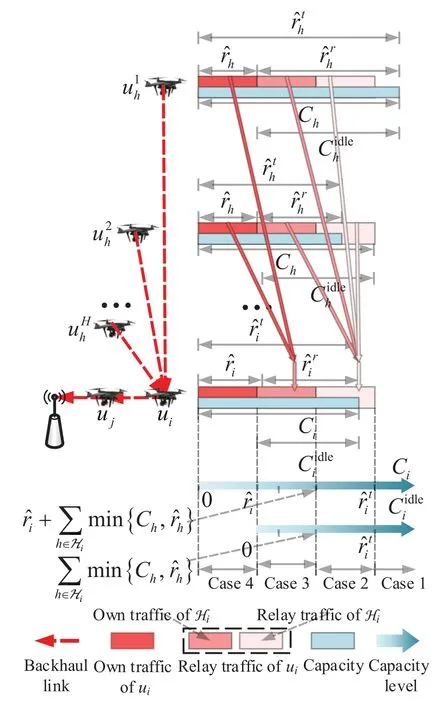
Figure 3.Illustration of transmission priority and 4 different cases in algorithm 3.The deeper the red color of traffic requirement,the higher is the transmission priority.The blue rectangles are the total capacity of multiple subchannels.The transmission rate of a one-hop link equals to the smaller of channel capacity and traffic requirement.The two gradual blue arrows stand for the level of Ci and Cidlei,respectively.With the increase of Ci and Cidlei,the BR of ui corresponds to case 4 to case 1 in algorithm 3.
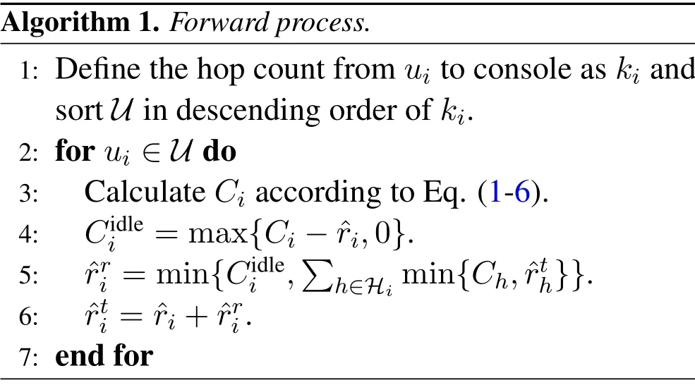
Algorithm 1.Forward process.1: Define the hop count from ui to console as ki and sort U in descending order of ki.2: for ui ∈U do 3: Calculate Ci according to Eq.(1-6).4: Cidle i =max{Ci −ˆri,0}.5: ˆrri =min{Cidlei,images/BZ_280_638_2768_686_2813.png h∈Hi min{Ch,ˆrth}}.6: ˆrti = ˆri+ˆrri.7: end for
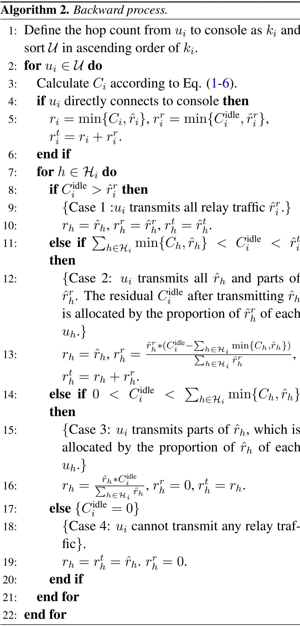
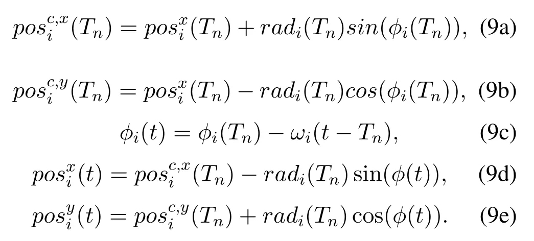
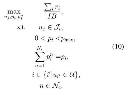
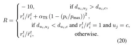
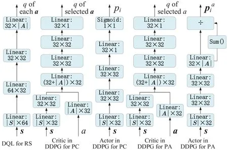
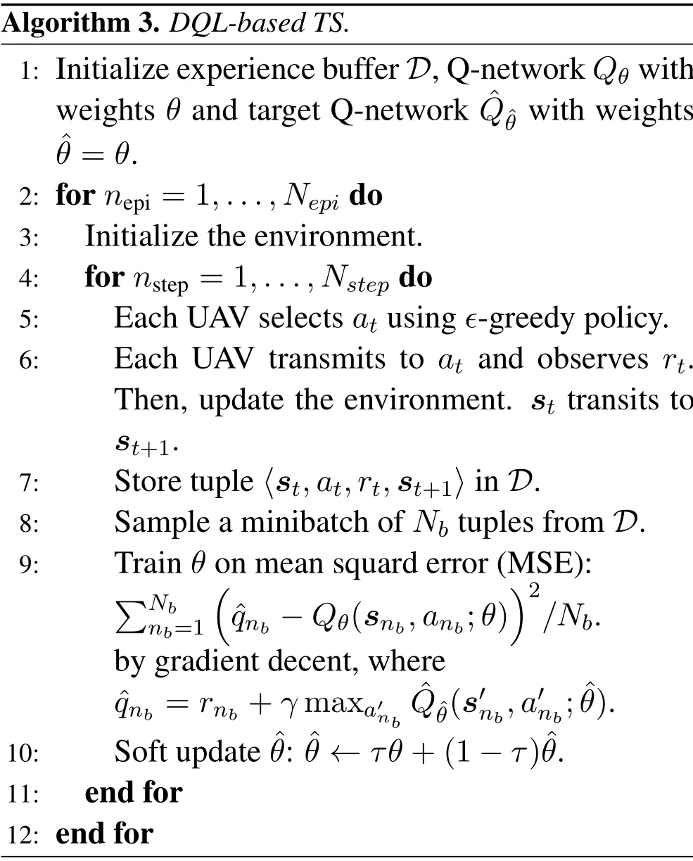
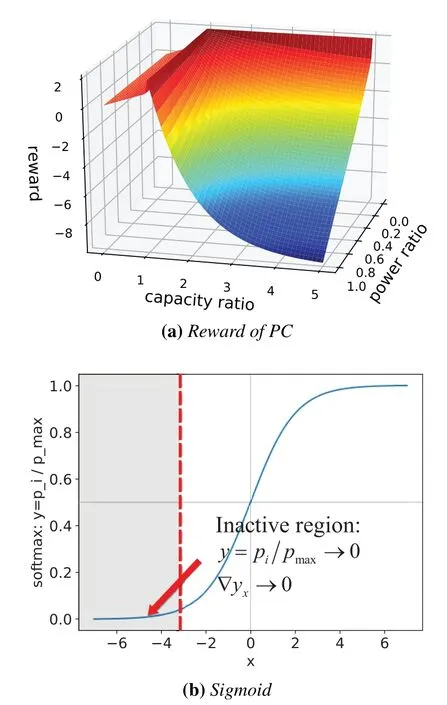
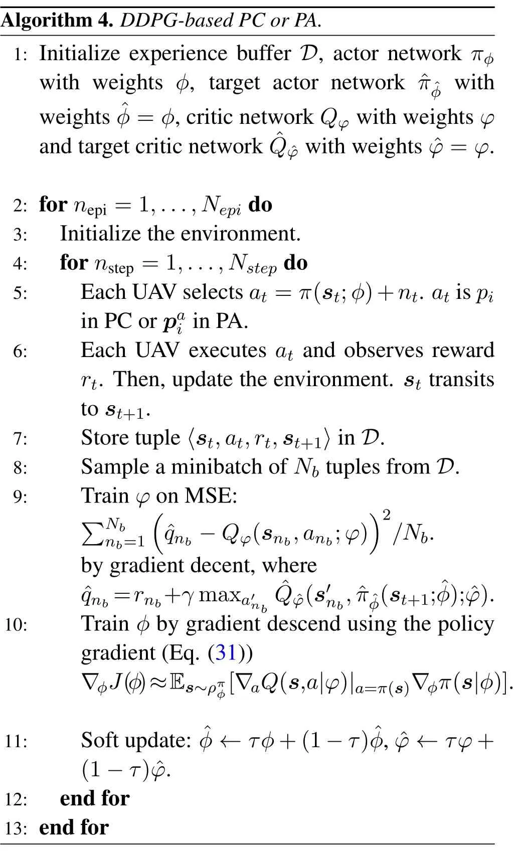
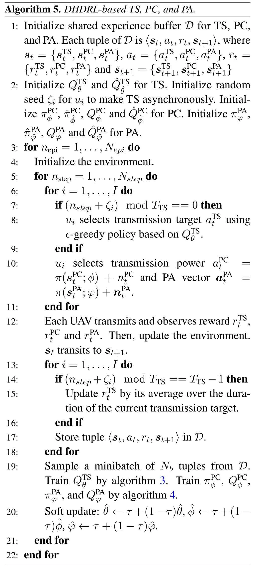
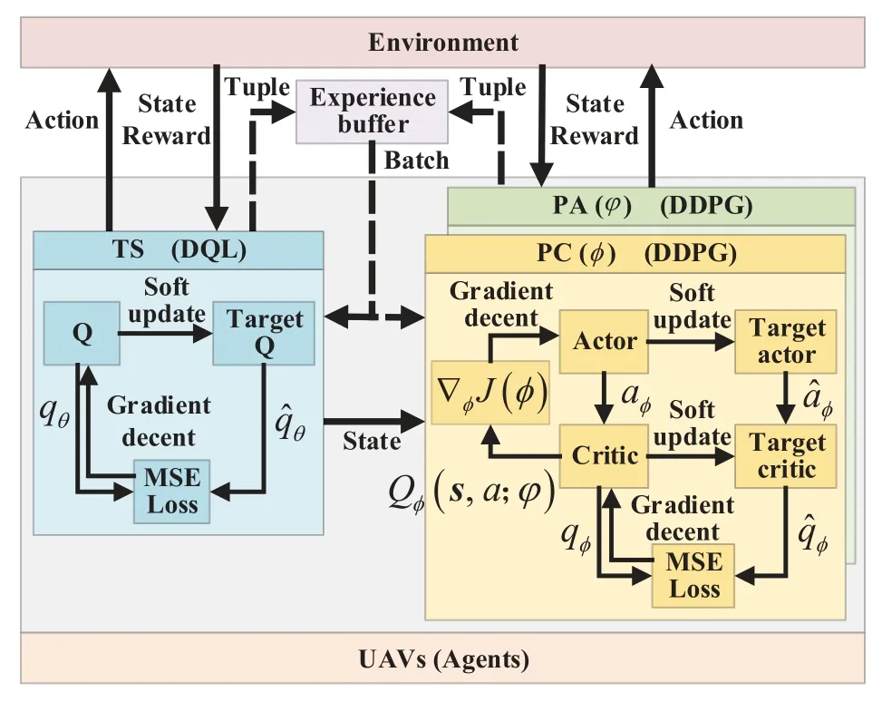
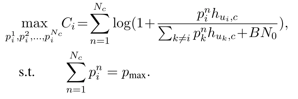
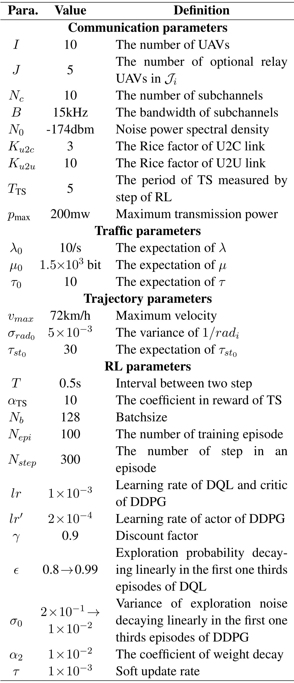
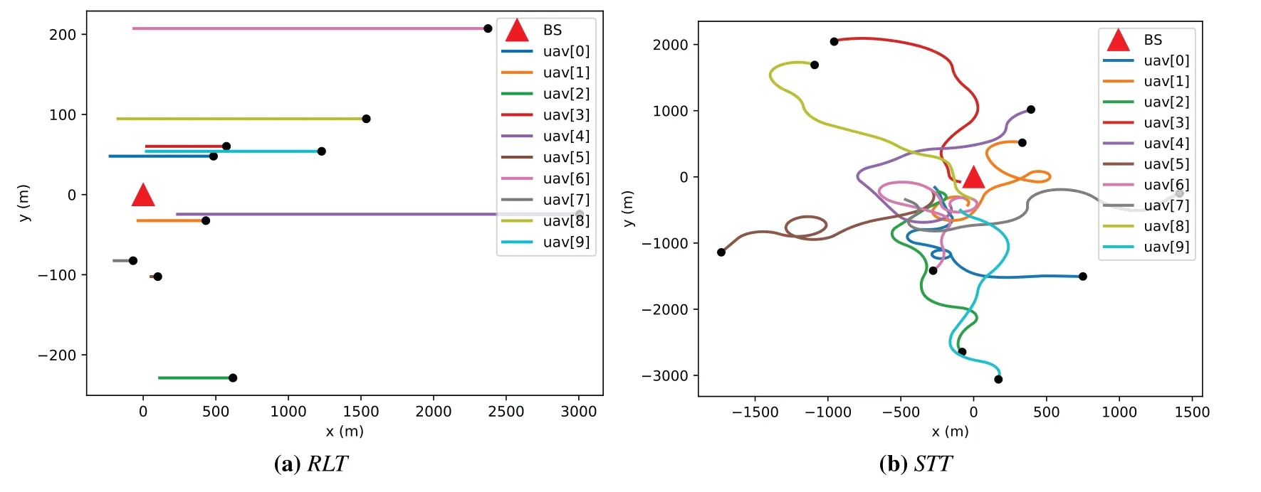
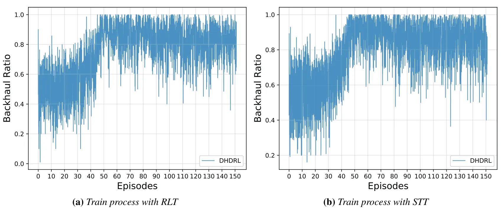
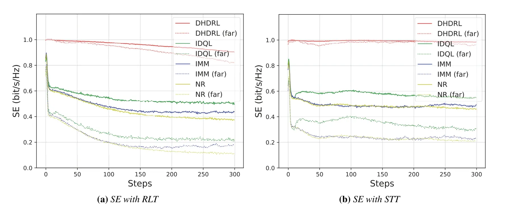
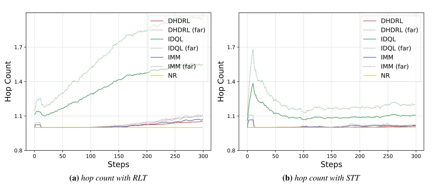
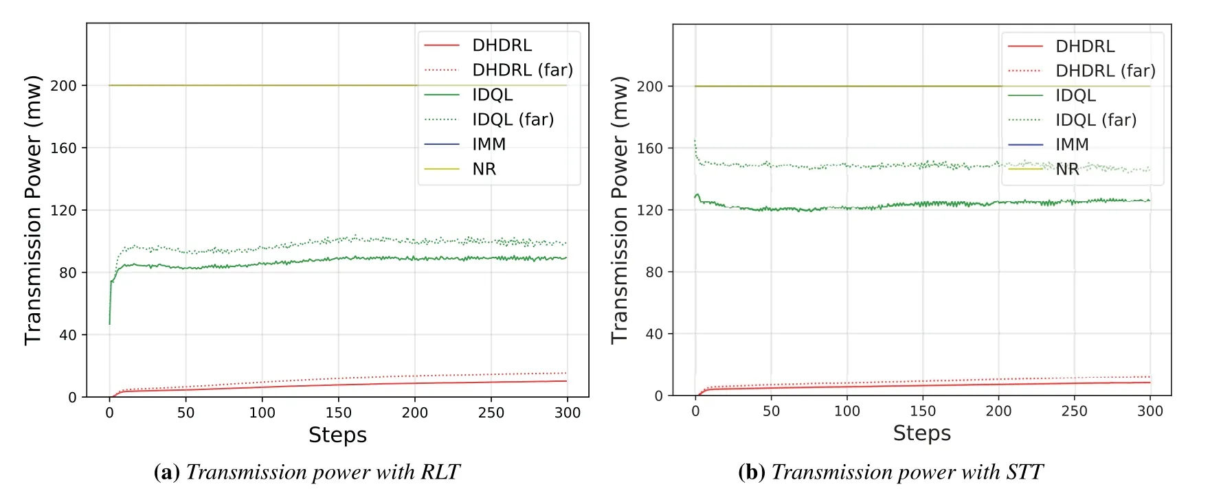
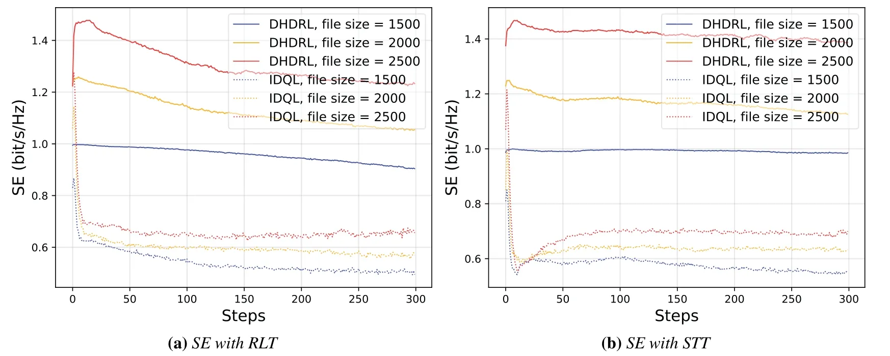
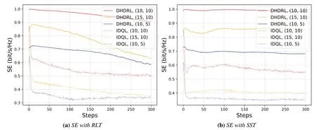
Algorithm 2.Backward process.1: Define the hop count from ui to console as ki and sort U in ascending order of ki.2: for ui ∈U do 3: Calculate Ci according to Eq.(1-6).4: if ui directly connects to console then 5: ri =min{Ci,ˆri},rri =min{Cidlei,ˆrri},rti =ri+rri.6: end if 7: for h ∈Hi do 8: if Cidlei > ˆrri then 9: {Case 1:ui transmits all relay traffic ˆrri.}10: rh = ˆrh,rrh = ˆrrh,rth = ˆrth.11: else ifimages/BZ_280_1561_1087_1580_1132.pngimages/BZ_280_1580_1053_1629_1098.png h∈Hi min{Ch,ˆrh} < Cidlei < ˆrti then 12: {Case 2: ui transmits all ˆrh and parts of ˆrrh.The residual Cidlei after transmitting ˆrh is allocated by the proportion of ˆrrh of each uh.}13: rh = ˆrh,rrh =ˆrrh∗(Cidle i −∑h∈Hi min{Ch,ˆrh})∑rth =rh+rrh.14: else if 0 < Cidle h∈Hi ˆrrh,i We assume that console is located at the original point.All UAVs are uniformly scattered in a square area with 500 meters width centering at console in the beginning.The position ofuiis defined asposi={posxi,posyi,poszi},whereposzi= 100m.The velocities of all UAVs are i.i.d and obey uniform distributionvi ~U(0,vmax).viis the velocity ofui.The maximum velocity isvmax= 72km/h.Two random trajectories are considered: 2.3.1 Random linear trajectory(RLT) Each UAV flies along x-axis withvi, Tnis the start time of stepn. 2.3.2 Smooth Trun trajectory(STT) Smooth turn[34,35]is a smooth trajectory considering tangential and centripetal accelerations.UAV selects a turning centerposci={posc,xi,posc,yi }along the line perpendicular to its heading directionφi,circles around it with the radiusradi=|posi −posci|for some timeτst,and then selects new turning center.The inverse length ofradifollows Gaussian distribution,i.e.,1/radi ~N(0,σrad0).τstfollows exponential distribution,i.e.,τst ~Exp(1/τst0) with expectationτst0.Angular velocityωi=vi/radi.The mobility state can be derived as follows[34]: Considering the above models,each UAV is devoted to select an optimal transmission target fromJifirst,which can be a relay UAV or console.Then,each UAV determinespiandpniof each subchannel.The optimization objective is to enhance the BR of the UAV network,which is determined by algorithms 1 and 2.For generality,we normalize the BR byBandI,and obtain spectral efficiency(SE)as the objective function.Then,the optimization problem is formulated as: According to algorithms 1 and 2,sinceriis impacted by network topology,dynamic traffic,transmission priority and congestion,it is difficult for optimization method to solve(10).Hence,we use DRL method to learn optimal decision policy by leveraging communication data. Considering each UAV as an agent,we propose DHDRL framework to select optimal transmission policy on TS,PC,and PA.In particular,DHDRL decomposes the backhaul framework into the three submodules first.Then,it tackles the three submodules by heterogeneous DRL methods with tailored rewards. General variable definitions are as follows.Sis the state set andAis the action set.Policyπis defined asπ:S →Awhich is the function to select action under current state,i.e.,a=π(s).In stept,agent under statest ∈Stakes actionat ∈A.Then,agent receives rewardrt=R(st,at),and state transits to next statest+1∈S.Ris the reward function.The action valueqtis the expected cumulative reward with respect toatandstwhich is defined asQ(s,a)is referred to as action-value function or Q-function.γis the discount factor.The general goal of an agent is to learn an optimal policy to maximize the expected cumulative reward.These variables are reused in Sections 3.3 and 3.4.In Section 3.5,they are superscripted by TS,PC,and PA to distinguish,respectively. The information collection process is as follows.In the beginning of one step,uicollectshui,candposjof all targets inJi.Based on these information,uiexecutes TS.Ifuiselects relay UAVs as transmission target,uicollectshui,ujfromuj.Then,uiexecutes PC and PA.Compared with aforementioned researches,we only use time-insensitive position information instead of CSI in TS.SinceJiandHiare the neighboring UAVs ofui,the local information exchange is within the lifetime of CSI. In DRL methods,Q-function andπof these methods are modeled by DNN.DNN is a multilayered model alternately stacked by linear layers and nonlinear activation layers.A linear layer and a nonlinear activation layer are referred to as a hidden layer.This structure endows DNN with powerful ability to fit complex functiony=H(x).The linear layer executes a linear computation whereWandbare weight and bias parameters,respectively.They are optimized by gradient descend algorithm whose gradients are calculated by backpropagation algorithm.The nonlinear activation layer executes nonlinear mapping.The nonlinear unit we used is rectified linear unit(ReLU)which is Sigmoid layer is used as the output layer in DDPG for PC,i.e., We utilize DQL to tackle TS since its action space is discrete and enumerable,i.e.,Ji= 3.3.1 State The state ofuiis defined as which is the collection of the profile ofuiandujinJi.proficonsists of total traffic,position,the distance betweenuiand console,and CSI of U2C link,i.e., profjconsists of position,the distance betweenuianduj,and two distance-related ratios,i.e.,ηi,jandξi,j. ηi,jis the distance increase ratio of relay linkui →uj →cto direct linkui →c.ξi,jreflects the farness ofuj.Since TS lastsTTSsteps,all items inprofjis only related to distance which is more time-insensitive and slow-changing than CSI.It is benefit to alleviate the effect of small-scale fading. 3.3.2 Action The action of DQL is the transmission target selected fromJi.We propose a heuristic approach to selectJoptional targets intoJifromUi−in order to filter unnecessary options. • First,distantujis excluded fromJiifduj,c >dui,c. • Second,theJUAVs with topscorejinUi−are selected intoJiin ascending order. ξi,jfiltersujclose touito reduce needless relay,while max{1−ηi,j,0}prevents from selectingujwhose relay link distance is too far. • Third,foruiclose to console,the number of selectedujinJiis less thanJ.The free positions inJiare filled with console treated as a relay UAV. 3.3.3 Reward We design the reward of TS on account of the following reasons: • TS is the first submodule and is with the longest period among the three submodules.Hence,the reward should considerrticonsisting of both own and relay traffic. • For reducing the needless relay,the reward needs to be modified.Normalization,i.e.,rti/,is the basic of the modification. Therefore,we apply the BR ratio as the basic,which is the ratio of actual total BR to total traffic requirement,i.e.,rti/ˆrti.Then,we define the modified reward as follows: αTSis a modification factor.In case 1,the transmission target farther than console is severely punished.In case 2,when all traffic is transmitted,i.e.,rti/= 1,anduidirectly connects to console,piis lower,the target is more encouraged.This modification is used to cut down needless relay because,in such case,uihas enough ability to complete transmission tasks without a relay.In case 3,since the traffic requirement cannot be satisfied,we do not modify the reward to encourage DQL to explore a better transmission target. 3.3.4 DQL algorithm DQL learnsQ(s,a) to approximate the optimalQ∗(s,a)which obeys the Bellman optimality equation The DQL algorithm is shown in algorithm 3.In order to make the training process stable[23],we establish Q-networkQθwith weightsθand target Q-networkwith weights.DQL usesto estimateqand updatesby soft update which combinesθandwithτ ≪1.We useQθandwith the same architecture as shown in figure 4 to evaluateqof all actions at once,and then selectaby∊-greedy policy.∊-greedy policy greedily selectsawith maximumqwith probability∊,i.e.,a= arg maxa Q(s,a),otherwise,it randomly selectsa.Each episode containsNstepsteps.The batchsize isNb.Note that the initialization and the update of the environment includes the update of communication environment,traffic and trajectory. Figure 4.Architectures of used DRL models. Algorithm 3.DQL-based TS.1: Initialize experience buffer D,Q-network Qθ with weights θ and target Q-network ˆQˆθ with weights ˆθ =θ.2: for nepi =1,...,Nepi do 3: Initialize the environment.4: for nstep =1,...,Nstep do 5: Each UAV selects at using ∊-greedy policy.6: Each UAV transmits to at and observes rt.Then,update the environment.st transits to st+1.7: Store tuple〈st,at,rt,st+1〉in D.8: Sample a minibatch of Nb tuples from D.9: Train θ on mean squard error(MSE):ˆqnb −Qθ(snb,anb;θ)■2/Nb.by gradient decent,where ˆqnb =rnb +γ maxa′nb ˆQˆθ(s′nb,a′nb;ˆθ).10: Soft update ˆθ: ˆθ ←τθ+(1 −τ)ˆθ.11: end for 12: end for images/BZ_283_1442_1876_1490_1922.pngNb nb=1■ Since DQL selectsa= arg maxa Qθ(s,a;θ) based on the evaluation ofqof eacha,it cannot be extended to continuous action space whose actions cannot be enumerated.Thus,it is difficult for DQL to realize fine-grained PC and PA.Different with DQL,DDPG directly selects action bya=π(s) without the evaluation ofqof eacha.Therefore,DDPG can output continuous action,i.e.,fine-grained PC and PA. 3.4.1 State Afteruiselects transmission targetuj ∈Hibased on TS,the state of PC consists of total traffic,distance,and CSI betweenuianduj,i.e., Note that theujselected fromJican not only relay UAV,but also console.Then,uiselects total transmission powerpibased on DDPG.The state of PA consists ofandpi,i.e., 3.4.2 Action The action of PC ofuiis defined as The action of PA ofuiis the normalized PA vectorpai,where each elementpnais the ratio ofpniof subchannelntopi,i.e., 3.4.3 Reward Since the BR ratio of multi-hop link has been considered in TS,the core goals of PC and PA are to enhance the transmission efficiency of a one-hop link. The reward of PC: For alleviating MPC,pishould match traffic requirement,i.e.,Hence,we design where It is shown in figure 5a.The main idea ofRPCis: Figure 5.(a)Reward of PC versus capacity ratio Ci/and power ratio pi/pmax.(b)Illustration of inactive region and vanishing gradient. •RPCshould be asymmetric on the two sides ofand punish oversized power.Conversely,the symmetric reward prefers oversized power,because the oversized power can achieve similar BR.In the end,the symmetric reward fails to control the interference. • Further considering the characteristic of DNN,since we use a sigmoid layer as the output layer in PC to output The immoderate punishment of oversizedpisuppresses the outputpi/pmaxtoward 0.This trend makes the sigmoid layer get trapped in the inactive region as shown in figure 5b,where both the output and gradient are close to 0.This phenomenon is referred to as vanishing gradient[36]and degrades the performance.Consequently,the power is lower,the punishment is lower. Hence,ifx ∈(0,1),we useRPC=x ∈(0,1)as reward without modification.Ifx >1,piis oversized andRPCgradually decreases with the increase ofx.In particular,whenxis a little greater than 1,RPC∈(0,2),which is a guard interval for proper oversizedpi.Ifxcontinues to increase,RPC∈(0,−10)punishes oversized power.kcontrols the degree of punishment to prevent DNN from getting trapped in the inactive region. The reward of PA:Since TS considers the multi-hop BR and PC matches traffic requirement with properpi,the goal of PA is to enhance the SE of one-hop link.For getting rid of the impacts of topology and traffic requirement,we useCiinstead ofriin the SE of a one-hop link.Hence,we have 3.4.4 DDPG algorithm DDPG[37]is based on actor-critic architecture where agent jointly learns bothπφ:S →Awith parametersφby the actor,andQϕ(s,a)with parametersϕby the critic.DDPG aims at obtaining maximum expected rewardJ(πφ)from the state distributionρπφdetermined byπφ. DDPG directly selectsa=πφ(s) by the actor and uses the critic to evaluate the expected reward of the selecteda.Both the actor and critic are improved by the interaction. On the one hand,DDPG trains the actorπφwith parametersφbased on the gradient∇φJ(πφ) which is estimated by policy gradient theorem [26]and deterministic policy gradient theorem[38].The authors proved In terms of calculation,according to the chain rule,∇φJ(φ) is the expectation of gradient ofQ(s,a|ϕ)with respect toφ,whereQ(s,a|ϕ)is estimated by the critic.On the other hand,DDPG trainsQϕ(s,a) as DQL,whereais selected byπφ,and adds exploration noise obeying gaussian distributionn ~N(0,σ0) to explore the action space.Since PC and PA both use DDPG,for conciseness,we describe the common process of DDPG using identical symbols in algorithm 4.Detailed description combining with the three submodules is given in Section 3.5. Algorithm 4.DDPG-based PC or PA.1: Initialize experience buffer D,actor network πφ with weights φ,target actor network ˆπˆφ with weights ˆφ=φ,critic network Qϕ with weights ϕ and target critic network ˆQˆϕ with weights ˆϕ=ϕ.2: for nepi =1,...,Nepi do 3: Initialize the environment.4: for nstep =1,...,Nstep do 5: Each UAV selects at =π(st;φ)+nt.at is pi in PC or pai in PA.6: Each UAV executes at and observes reward rt.Then,update the environment.st transits to st+1.7: Store tuple〈st,at,rt,st+1〉in D.8: Sample a minibatch of Nb tuples from D.9: Train ϕ on MSE:ˆqnb −Qϕ(snb,anb;ϕ)■2/Nb.by gradient decent,where ˆqnb=rnb+γ maxa′nb ˆQˆϕ(s′nb,ˆπˆφ(st+1;ˆφ);ˆϕ).10: Train φ by gradient descend using the policy gradient(Eq.(31))∇φJ(φ)≈Es~ρπφ[∇aQ(s,a|ϕ)|a=π(s)∇φπ(s|φ 11: Soft update: ˆφ ←τφ+(1 −τ)ˆφ,ˆϕ ←τϕ+(1 −τ)ˆϕ.12: end for 13: end for images/BZ_285_1442_1311_1490_1356.pngNb nb=1■)] The DDPG models of PC and PA are shown in figure 4.Note that,different with DQL,the critic in DDPG only estimatesqof the selecteda.Hence,in each critic,the input is [s,a],whereais selected by the actor and adds exploration noise.In each actor,the output layer depends on its submodules.In PC,the output layer is sigmoid layer,which maps the output to(0,1)to representpi/pmax.In PA,the output layer is a linear normalization layer,i.e.,,whose output is the PA vector,i.e.,y=pai. Algorithm 5.DHDRL-based TS,PC,and PA.1: Initialize shared experience buffer D for TS,PC,and PA.Each tuple of D is〈st,at,rt,st+1〉,where st = {sTSt,sPCt,sPAt }, at = {aTSt,aPCt,aPAt }, rt ={rTS t,rPCt,rPAt }and st+1 ={sTSt+1,sPCt+1,sPAt+1}2: Initialize QTS θ and ˆQTSˆθ for TS.Initialize random seed ζi for ui to make TS asynchronously.Initialize πPCφ,ˆπP Cˆφ,QPCφ and ˆQP Cˆφ for PC.Initialize πPAϕ,ˆπPAˆϕ,QPAϕ and ˆQPAˆϕ for PA.3: for nepi =1,...,Nepi do 4: Initialize the environment.5: for nstep =1,...,Nstep do 6: for i=1,...,I do 7: if(nstep+ζi) mod TTS ==0 then 8: ui selects transmission target aTSt using∊-greedy policy based on QTS θ .9: end if 10: ui selects transmission power aPCt =π(sPC t ;φ) + nPCt and PA vector aPAt =π(sPA t ;ϕ)+nPAt .11: end for 12: Each UAV transmits and observes reward rTSt,t and rPAt .Then,update the environment.st transits to st+1.13: for i=1,...,I do 14: if(nstep+ζi) mod TTS ==TTS −1 then rPC 15: Update rTSt by its average over the duration of the current transmission target.16: end if 17: Store tuple〈st,at,rt,st+1〉in D.18: end for 19: Sample a minibatch of Nb tuples from D.Train QTS θ by algorithm 3.Train πPCφ, QPCφ,πPAϕ,and QPAϕ by algorithm 4.20: Soft update: ˆθ ←τ+(1−τ)ˆθ,ˆφ ←τ+(1−τ)ˆφ,ˆϕ ←τ +(1 −τ)ˆϕ.21: end for 22: end for The joint DHDRL framework is the integration of the three submodules.The DHDRL is shown in algorithm 5.Figure 6 is the overview of DHDRL.Note that the reward of TS is averaged over the duration of the current transmission target in step(13-18). Figure 6.The overview of DHDRL. • No relay(NR):NR is a plain baseline.All UAVs directly connect to console with maximum power allocated by water filling (WF) algorithm which solves the problem • Improved max-min method(IMM):This method assumes that all UAVs transmit with maximum power allocated by WF.In IMM,each UAV evaluatesCui,cfirst.Then,ifCui,cis greater thanUAV directly connects to console.Otherwise,UAV selects relay UAV by max-min method,i.e.,UAV selects relay UAV to maximize the minimum capacity between U2C and U2U links.This method is close to a greedy method and requires multi-hop CSI. • Integrated DQL(IDQL):Researches[14,25,24,13]utilize a single DQL model to select action combination of all subfunctions.For distinguishment,we refer to this method as integrated DQL(IDQL).In our settings,IDQL jointly executes TS and PC whose total power has 10 levels.Its reward is Eq.(20).PA uses WF. Jiof IMM and IDQL are also selected by the same proposed heuristic approach as DHDRL. We consider the scenarios that 10 UAVs fly around a console with RLT and STT as shown in figures 7a and 7b,respectively.The parameters are given in Table 2.The DHDRL models are trained by Adam [39]with weight decay coefficientα2=1×10⁻². 4.3.1 Training process and convergence For eliminating the impact of dynamic traffic and needless relay,the training process of DHDRL is validated by the average BR ratio of own traffic,i.e.,ri/ˆri,over all UAVs versus training episodes in figures 8a and 8b.DHDRL guarantees the convergence with different trajectories,although the fluctuation range of the BR ratio is somewhat large.This fluctuation is caused by the inherent differences among all random episodes. 4.3.2 Performance analyses We make comparisons in terms of three metrics,which are SE in Eq.(10),hop count,and transmission powerpiversus steps.All metrics are validated with both RLT and STT corresponding to the left pictures (a)and the right pictures (b),respectively.As shown in figures 7a and 7b,the steps are proportional to the distance between UAVs and console.Hence,RLT with obvious moving direction is used to analyze UAVs’behaviors,and STT with randomness is used to validate the stability of DHDRL.To validate the performance of far-end UAVs,which have the most urgent requirement of an backhaul framework,the dotted lines in figures 9a-11b are the performance averaged over the farthest half of UAVs.All simulation results are averaged over 200 random episodes. The results in figures 9a and 9b show DHDRL outperforms all compared methods in SE obviously.The gaps between the farthest half of UAVs and all UAVs are less than all compared methods,which means DHDRL guarantees the BR of far-end UAVs effectively.Besides,with the increase of steps,the decrease of SE of DHDRL is slower,which means DHDRL optimizes transmission policy to adapt to movement. Table 2.Parameter setting. In STT,as shown in figure 9b,SE of DHDRL fluctuates slightly because UAVs almost transmit all traffic requirements benefitting from DHDRL and the closer distance than RLT. The results in figures 10a and 10b show DHDRL reduces needless relay.In addition,in the first 20 steps,some UAVs are very close to console,such as UAV 1 in figure 7a and UAV 1 in figure 7b,which cause severe interference to the other UAVs.As a result,some far-end UAVs in IDQL and IMM request relay transmission even they are not very far from console.Different with IDQL,DHDRL avoids this problem by average reward and PC. Figure 7.Trajectory examples of RLT and STT.The black points are the terminal points of UAVs in an episode. Figure 8.Training process validated by the BR ratio of own traffic versus training episodes. The results in figures 11a and 11b show DHDRL effectively controls transmission power,which is a synthetic result of both PC and PA.Note that the transmission power of IDQL is close to half of maximum power,which implies MPC forces far-end UAVs to reach the maximum power.In addition,although the average distance with STT is closer than that with RLT,in IDQL,the average power with STT is larger.This is because some spiral UAVs,such as UAV 1 in figure 7b,fail to control power,and cause severe interference to the other UAVs from beginning to end.As a result,MPC appears.All the above confirms that MPC cannot be effectively alleviated by IDQL.However,DDPG executes PC based on tailored reward and outputs fine-grained transmission power,which further reduces superfluous transmission power caused by power discretization. Combing figures 9a-11b,DHDRL achieves systemlevel and all-around gain,i.e.,higher SE,lower transmission power and fewer hops.Some synthetic analyses are as follows: Figure 9.The SE of own traffic versus steps in an episode.The dotted lines are the average SE of the farthest half of UAVs. Figure 10.Hop count versus step in an episode.The dotted lines are the average hop count of the farthest half of UAVs. Figure 11.Transmission power versus step in an episode.The dotted lines are the average transmission power of the farthest half of UAVs. • TS benefits from PC and PA: PC and PA of DHDRL control interference notably.Therefore,far-end UAVs reach maximum power and begin to request relay when they are extremely away from console,which avoids needless relay and congestion. • PC and PA benefit from TS:TS reduces needless relay,and consequently,the traffic burden of relay UAVs.Therefore,relay UAVs do not need to enhance transmission power to transmit high traffic,which is conducive to alleviate MPC. • The necessity of decomposition and tailored rewards: From the bottom-up view of IDQL,the sole reward,enhancing BR,cannot alleviate MPC.As a result,far-end UAVs suffer strong interference and have to request relay,and congestion possibly appears.These factors limit the performance of IDQL.Therefore,the decomposition and tailored rewards are crucial. According to figures 9a and 9b,DHDRL almost transmits all traffic.Hence,we validate its performance in high traffic environment and more competitive environment.First,in figures 12a and 12b,we validate the effect of traffic on SE by setting the file sizeµ0from 1.5×103bit to 2.5×103bit.In DHDRL,since UAVs only use a little power whenµ0= 1.5×10³,they have enough residual power to transmit more traffic.Conversely,UAVs in IDQL just have little residue power and their SE can not be improved obviously any more.In addition,in the first few steps,the SE of IDQL decreases quickly because IDQL cannot efficiently alleviate MPC.Second,in figures 13a and 13b,with the increase of UAVs and the decrease of subchannels,the competition is intensified.Either way,DHDRL always outperfroms IDQL. Figure 12.The effect of traffic on the SE of own traffic versus steps.The traffic is setted by the file sizeµ0 from 1.5×103 bit to 2.5×103 bit Figure 13.The effect of the number of UAVs and subchannels on the SE of own traffic versus steps.In the suffixal bracket,the first parameter is the number of UAVs from 10 to 15,and the second parameter is the number of subchannels from 10 to 5. In summary,although DHDRL decomposes the backhaul framework,it achieves system-level performance gain compared with the non-DRL method and DRL methods.Meanwhile,this performance gain is validated by all-around metrics,such as two random trajectories,SE,total power,hop count,and other parameters of UAV networks. In this paper,to enhance the BR of UAV networks,we propose DHDRL to construct a distributed and LIB backhaul framework jointly considering topology construction and power adjustment.First,we establish the transmission model considering high mobility,dynamic traffic,transmission priority,and congestion.Then,we propose DHDRL to construct the backhaul framework.DHDRL decomposes the backhaul framework into three submodules,i.e.,TS,PA,and PC,with specific requirements and tackles them by heterogeneous DRL methods with tailored rewards.In particular,TS is solved by DQL to guarantee BR and reduce needless relay.PC and PA are dealt with DDPG to match traffic requirements with proper finegrained transmission power.As a result,MPC is effectively alleviated and the potential of BR is further released.Finally,the simulation results show that DHDRL achieves system-level and all-around performance gain,which enhances BR notably with low hop count and transmission power.The performance gain is validated by different trajectories and various parameters of UAV networks.In summary,For a multi-function problem which is difficult to solve by optimization methods,decomposition and tailored rewards construct a bridge between communication knowledge and DRL,which is worthy to explore. NOTES 1In this paper,the static topology means only the transmission mode is unchanged,but in relay transmission mode,the source UAVs can change their selected relay UAVs. 2For example,the coherence timeTc ≈7.5ms whenv=20m/s andfc=2GHz,which means the millisecond-level delay of exchanging multi-hop CSI and iteration are non-negligible burden of making decision. 3Variables superscripted by hat are traffic requirement;variables without hat are actual backhaul rate;variables without superscript are their own traffic;variables superscripted byrare relay traffic;variables superscripted bytare total traffic.2.3 Mobility Model

2.4 Problem Formulation
III.THE PROPOSED DHDRL FRAMEWORK
3.1 Deep Reinforcement Learning
3.2 Deep Neural Network


3.3 DQL-Based TS



3.4 DDPG-Based PC and PA




3.5 DHDRL of TS,PC,and PA
IV.SIMULATION RESULTS
4.1 Compared Schemes
4.2 Simulation Settings
4.3 Performance Analysis
V.CONCLUSION
- China Communications的其它文章
- Energy Model for UAV Communications: Experimental Validation and Model Generalization
- Joint Computing and Communication Resource Allocation for Satellite Communication Networks with Edge Computing
- An Intelligent Scheme for Slot Reservation in Vehicular Ad Hoc Networks
- CLORKE-SFS:Certificateless One-Round Key Exchange Protocol with Strong Forward Security in Limited Communication Scenarios
- Information-Defined Networks: A Communication Network Approach for Network Studies
- Deep Learning Based User Grouping for FD-MIMO Systems Exploiting Statistical Channel State Information

