A progressive approach to predict shot peening process parameters for forming integral panel of Al7050-T7451
Chuang LIU, Zhiyong ZHAO, Xianjie ZHANG, Junbiao WANG
School of Mechanical Engineering, Northwestern Polytechnical University, Xi’an 710072, China
KEYWORDS Curvature radius measure;Integral panel;Process parameters prediction;Regressive analysis method;Shot peening process
Abstract In this paper,a progressive approach to predict the multiple shot peening process parameters for complex integral panel is proposed. Firstly, the invariable parameters in the forming process including shot size,mass flow,peening distance and peening angle are determined according to the empirical and machine type.Then,the optimal value of air pressure for the whole shot peening is selected by the experimental data. Finally, the feeding speed for every shot peening path is predicted by regression equation. The integral panel part with thickness from 2 mm to 5 mm and curvature radius from 3200 mm to 16000 mm is taken as a research object, and four experiments are conducted. In order to design specimens for acquiring the forming data, one experiment is conducted to compare the curvature radius of the plate and stringer-structural specimens, which were peened along the middle of the two stringers.The most striking finding of this experiment is that the outer shape error range is below 3.9%, so the plate specimens can be used in predicting feeding speed of the integral panel.The second experiment is performed and results show that when the coverage reaches the limit of 80%, the minimum feeding speed is 50 mm/s. By this feeding speed, the forming curvature radius of the specimens with different thickness from the third experiment is measured and compared with the research object, and the optimal air pressure is 0.15 MPa. Then,the plate specimens with thickness from 2 mm to 5 mm are peened in the fourth experiment,and the measured curvature radius data are used to calculate the feeding speed of different shot peening path by regressive analysis method.The algorithm is validated by forming a test part and the average deviation is 0.496 mm. It is shown that the approach can realize the forming of the integral panel precisely.
1. Introduction
Integral panel is the main structural component of aircraft wing because of its high structure efficiency, smooth aerodynamic configuration,short process preparation cycle and fewer fabrication hours.1,2As the skin and stringers are integral,and the curvature and thickness are variable, it is difficult to form such a wing panel. Homer and Luchene3revealed that shot peening process ranks as one of the major processes for integral panel in aerospace manufacturing.Nam,et al.4Hu,et al.5show that the surface of a metal sheet impacted by small hard shots with sufficient kinetic energy controlled by shot peening parameters can form a specific shape without need for forming die,and Bagherifard,et al.6found that it can also improve the fatigue resistance of component significantly.
Shot peening process parameters include shot size,air pressure, feeding speed, mass flow, peening distance and peening angle. Meguid, et al.7indicated the repeatability of the shot peening process combined with different shot peening parameters is usually measured using two control parameters: peening intensity and peening coverage. However, shot size is usually determined according to the type of shot machine,and the peening distance and peening angle are always set as constants in order to make it convenient for operation, and usually keeping air pressure and the mass flow as constant as possible, only by adjusting feeding speed of the nozzle to control the shot distribution density on the workpiece surface to change the deformation.
How to design the shot peening process parameters accurately and quickly is the key to form the integral panel. In the past decade, many studies mainly including analytical,FEA and experimental methods have been proposed to predict the parameters of shot peening process accurately. The methods based on analytical calculation and FEA aim at analyzing the mechanism of shot peen forming and developing the analytical model according to the relationship between stress and strain. Zhang, et al.8use the cross-sectional liner indentation coverage method on the basis of the spherical cavity model to establish an analytical expression between stress and deformation corresponding to different coverage. Levers and Prior9suggested a thermal loading method to simulate peen forming processes, though introducing stress distributions in shell elements by creating thermal strains. Garie´py,et al.10proposed an equivalent stress method that loaded induced stresses in the path region of strips and used the linear solution method to simulate the deformation of the wing panel. It’s usually realistic processing with assumptions for simplifying the calculation due to the complexity of the shot peening mechanism. Therefore, the method can only be used for qualitative analysis,and it is difficult to predict the process parameters accurately.
Experimental methods can directly obtain the relationship between shot peening process parameters and deformation of different structural specimens as Miao, et al.11indicated. Previous studies were focused on small-size, equal-thickness plate structure with equal curvature,and used multi-regression analysis and neural network to establish a process parameters prediction model.
Kulkarni and Badger12established the quantitative relationship between the curvature radius and the shot density by a systematic experimental investigation conducted on 2024-T3 and 7075-T6 aluminum alloy sheets.But the accuracy of the established function is not verified. Bai, et al.13developed relationships among feeding speed, air pressure, prestress and the shaped curvature radius through regression analysis method on Al-Li alloy 2198 plate to calculate the shot parameters.As the experiment was conducted at one thickness,the regression model can only calculate the shot parameters at this thickness.Based on the research,Huang and Zeng14introduced the influence of part thickness, but the model is not the actual integral panel for validation. Delijaicov, et al.15developed a mathematical model to describe the relationships among the thickness of part, shot diameter, impact velocity,coverage, pre-stress and the maximum deflection based on the multivariable regression and neural network according to the experiment results on aluminum alloy 7050 and 7475 plates. And the result indicated that the model generated by the regression method was still more accurate than the one issued by the neural network. This is, probably, due to the small quantity of experimental data used to train the neural network.Zhang,et al.16used BP artificial neural network algorithm for predicting the parameters of shot peening. The neural networking peening parameter predict method relies on the selection of the training data, and only enough training data and repeated training can achieve high prediction precision.
As the integral panel has the characteristics of variable thickness, variable curvature and stringers, a key limitation of the above experimental method is that it does not consider varies of the corresponding geometrical dimensions and structural features of the parts. The methods mentioned above are limited to predict parameters of plate structure, not an actual integral panel. At the same time, the selection of the parameters of the shot peening process is not discussed in detail.Thus,the method of trial and error is still used in engineering to design the shot peen forming process parameters as Li,et al.17revealed.Not only is it time and cost consuming,but also cannot meet the acceptable error range.
This paper concerns the development of a progressive approach to predict shot peening process parameters for forming integral panel. The remainder of the paper is organized as follows four sections.Chapter 2 describes the characteristics of integral panel and framework of shot peening parameters. In chapter 3 the different forming radius of plate structure specimen and stringer-structural specimen is analyzed, and experiments about the determination of the variable parameters in forming the integral panel are presented. The regression analysis method to calculate shot peening process parameters is established based on forming experiments. Chapter 4 shows the parameters calculation process for the example part and the verification results of the integral panel. The conclusion is reported in Chapter 5.
2. Framework of shot peening process parameters design
2.1. Analysis of structural feature of integral panel
As shown in Fig. 1(a), the structural feature of the integral panel is composed of the base body and internal structural element, which is attached to the base body. The base body is a thick plate defined by the inner surface and the outer doubly-curved surface which is the theoretical shape of the aircraft.The internal feature mainly includes stringers,reinforced boss, sunk and frame, and directly contribute to forming parameters prediction.Reinforced boss,sunk and frame effect on base body, make its thickness different. Stringer-structural and base body integration forms the integral panel.Therefore,the influence of the stringers on the forming needs to be fully considered in the parameter prediction.
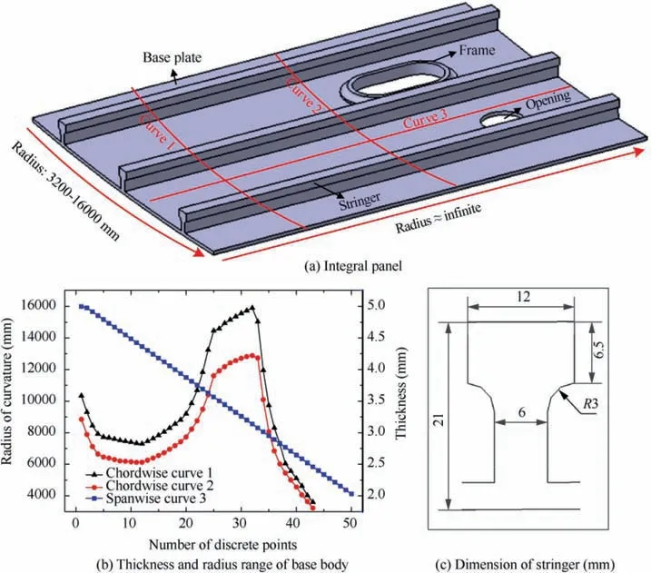
Fig. 1 Geometrical structure information of integral panel.
Three curves are randomly selected in the chordwise direction and spanwise direction of the integral panel as shown in Fig. 1, which were used to evaluate the curvature radius and thickness range of the integral panel by measuring the curvature and thickness along the curves. The curvature of two chordwise curves and the thickness of a spanwise were presented in Fig. 1(b), shows that the thickness of the base body is between 2 mm and 5 mm and the curvature radius is from 3200 mm to 16,000 mm in the chordwise direction. However,the curvature radius is greater than 20,000 mm in the spanwise direction, which is approximated no deformation. Therefore,the main forming direction is the chordwise direction. At the same time, the minimum chordwise curvature radius corresponding to the region with thickness less than 2 mm, and between 2 mm to 3 mm, 3 mm to 4 mm and 4 mm to 5 mm are 3289.47 mm, 5712.29 mm, 6993 mm and 8620.72 mm respectively. The feature of stringer is shown in Fig. 1(c); the thickness of the stringer is 21 mm, and the top and bottom width are 12 mm and 6 mm respectively. The corner radius between the top is 3 mm and the distance between the top stringer and the bottom stringer is 6.5 mm.
2.2. Shot peening process parameters
As shown in Fig.2,shot peening process is performed using an air blast type machine and the shot is impelled onto the workpiece by means of a blast of compressed air. The shot peening process parameters including shot size,air pressure,mass flow,peening angle, peening distance and feeding speed were demonstrated by Hong,et al.18The velocity of the shots is also a significant parameter of the shot peening process controlled by the air pressure. However, Guechichi, et al.19revealed that it is not used as a controlled parameter by the shot peeing industry. These parameters are divided into two categories by its variability in the forming process.The invariable parameters including shot size,mass flow,peening distance and peening angle are determined according to the empirical data and machine type before forming.The variable parameters include air pressure and feeding speed is usually adjusted in the integral panel forming process. As the hysteresis effect of the air pressure to the workpiece during the machine moving, the optimal air pressure is usually selected for the whole shot peening process and feeding speed is adjusted to ensure the forming efficiently. These parameters information is shown in Table 1.
Zhang, et al.8described the relation between the forming curvature radius and parameters as Eq. (1).

where R and t are the curvature radius and the thickness of component, v is the feeding speed, which presents the peening coverage. d is the depth of indentation, which presents the peening intensity is the comprehensive actions of air pressure,shot size and peening distance, as shown in Fig. 3. η is a coefficient to be determined by experiment, and K is a constant of the material defined by

where E is the Young’s modulus,υ is the Poisson’s ratio,and Y is the yield strength. Al-Obaid20defined the relation between the depth d and the spherical radius r of the indentation as
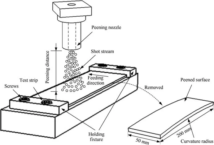
Fig. 2 Schematic diagram of shot peening.

Table 1 Shot peening process parameters.

where ρsis the mass density, V0is the incident speed of the shot, andis the average contact pressure.
From Eqs. (1)-(3) the feeding speed can be calculated according to the curvature radius, the thickness of part and the depth of indentation,but the depth of indentation are hard to be measured. Thus, the relationship between air pressure and peening intensity is hard to determine before shot peening.To a certain material and machine,the experiment can directly obtain the relationship between the curvature radius and shot peening parameters. In this paper, shot peen forming process was performed using a high precision mobile air blasting machine MPPF20000 and the material is Al7050-T7451,which is usually used in the wing integral panel. Its composition and mechanical properties are shown in Table 2.
2.3. Shot peen forming process parameters
As shown in Fig.4.A progressive approach based on empirical and experimental data is proposed to determine the multiple shot peening process parameters.
The invariable parameters including shot size, mass flow,peening distance and peening angle are determined according to the empirical and machine type before forming in the first step.ASH280 cast steel shots with the diameter 0.7 mm is used in the MPPF20000 machine. In addition, the suitable peening distance is 400 mm. The lower distance is prone to collision between machine and parts, and the higher distance leads to the dispersed shots and low kinetic energy. Furthermore, the nozzle perpendicular to the specimens during shot peening in order to obtain the higher kinetic energy and the suggested mass flow is set to 10 kg/min of the machine.
In the second step, four progressive experiments are conducted to select the optimal value of air pressure and the feeding speed corresponding to different thickness and curvature radius. In order to design specimens by the integral panel,the first experiment is conducted to compare the curvature radius of the plate and stringer by a digital curvature radius measuring method. No significant reduction of curvature radius in plate was found compared with stringer.So the plate specimens can be used in predicting the feeding speed of the integral panel.The second experiment is performed and results show that when the coverage reaches the limit of 80%, the minimum feeding speed is determined. By this feeding speed,the forming curvature radius of the specimens with different thickness from the third experiment is measured and compared with the integral panel part, and the optimal air pressure is selected. By this optimal air pressure and feeding speed range,the plate specimens of different from the integral panel base body are peened and the forming curvature radius is measured in the fourth experiment.
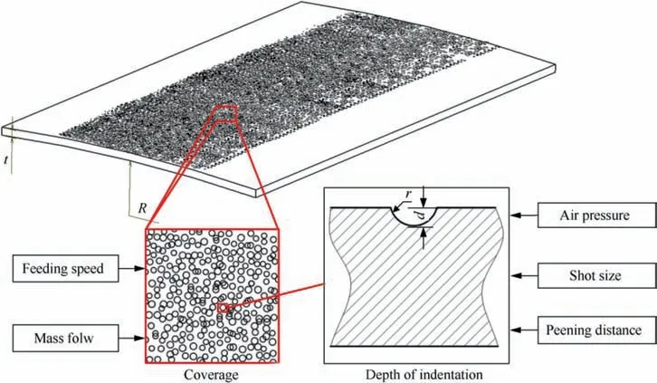
Fig. 3 Relationship between shot peening parameters.

Table 2 Properties of Al7050-T7451.
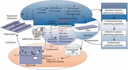
Fig. 4 Flowchart of shot peening parameters design.
In the last step,the measured curvature radius in the fourth experiment is used to establish the regression equation to calculate the feeding speed of different shot peening path and the algorithm is validated by forming a test part.
2.4. Measuring method of the curvature radius
For each experiment, the curvature radius measurement method plays a key role in ensuring the experimental data accuracy. Hu, et al.21used an arc height gauge to measure the forming curvature of specimens. However, as shown in Fig.5(a),the measured curvature radius was different by using different span arc height gauge for the same measure position that’s due to the shot disparity and induces deformation inhomogeneity. Thus, a 3D laser scanner was used to measure the curvature radius of peened specimens. In the first step, the opposite of specimens’peened surface was defined as the scanning surface due to the existed indentations of peened surface.Then, points clouds of the surface were collected through reverse engineering software. Once the surface scan was finished, the three-dimensional surface model of the specimen was reconstructed as shown in Fig. 5(b). Finally, the reconstructed three-dimensional surface model was imported into CAD software, and cross-section curves of the model were obtained. In order to decrease the inhomogeneity effect, three curves with 5 mm interval in the middle of the model were measured as shown in Fig. 5(c). The maximum curvature(i=1,2 3)of the section curve was taken as the forming curvature as shown in Fig. 5(d). And the average curvature radius of the three curves represents the forming curvature radius of the specimen as shown in Eq. (4).

3. Progressive determination of shot peening parameters
3.1. Determination of specimens structure
The different forming radius between plate and stringerstructural specimens need be compared to determine the structure for subsequent experiments. Plate specimens and T-shaped stringer-structural specimens with three kinds of base body thickness 2, 3 mm and 4 mm, 400 mm length and 138 mm width were peened in a constant pressure 0.15 MPa for six kinds of feeding speed: 65, 84.5, 109.9, 142.8, 185.6,241.3 mm/s, and along the middle of the species to forming.Therefore, a total of 48 specimens have been tested, and the specimens held by the clamp are shown in Fig. 6(a).
One formed specimen is shown in Fig. 6(b), and the measured curvature radius is shown in Fig. 7. The most striking observation to emerge from the data analysis was that the maximum difference of curvature radius between the Tshaped stringer-structural specimens and plate specimens is 139.6 mm at the speed of 185.6 mm/s in 3 mm thickness base body, and the outer shape error range is 3.9%. The difference gradually decreases with the increase of the thickness.
It can be seen that when the height of the stringer is higher than 21 mm and the width is less than 6 mm, the restraining effect of the stringer on the chordwise formation can be neglected, so plate can be used as the equivalent structure of T-shaped stringer to acquire experimental data for determination of process parameters.
3.2. Determination of feeding speed range
The coverage of the specimens is measured at different feeding speeds to determine the range of feeding speed (v1-vn). Plate specimens with 3 mm thickness, 200 mm length and 50 mm width were peened under three pressures of 0.1, 0.15,0.2 MPa and 12 kinds of feeding speeds, the variation range of feeding speed is from 33.33 mm/s to 700 mm/s, shown in Table 3. There are altogether 12 groups and 36 specimens.
3D Microscope was used to obtain the surface topography,and ImageJ software was used to evaluate surface coverage.Krik and Hollyoak22pointed out that the residual stress increases almost linearly at low coverage and reaches a maximum at 80% coverage. Sharp, et al.23reported that with the increase of the surface coverage of the specimen the surface roughness of the part increases,and Curtis,et al.24found that the fatigue life of the part decreases with the increase of the surface coverage. Therefore 80% coverage is defined as the maximum allowable coverage of the forming surface. Fig. 8 presents 2D measured topography images as well as evaluated surface coverage by ImageJ with feeding speed of 50 mm/s at different pressures 0.1, 0.15, 0.2 MPa. When the air pressure is 0.15 MPa and the feeding speed of the machine is 700 mm/s, as shown in Fig. 9, the surface coverage of the specimen is 5.8%,and the forming ability is basically not available.Therefore, the range of shot peening feeding speed is set from 50 mm/s to 700 mm/s.
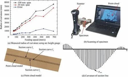
Fig. 5 Curvature radius measurement of specimens.

Fig. 6 Clamping method and formed stringer-structural specimens.
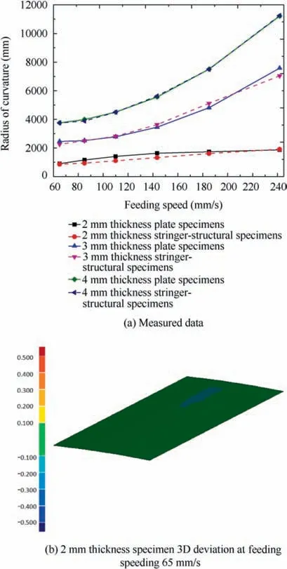
Fig. 7 Comparing results of curvature radius between plate and T-shaped stringer-structural specimens.

Table 3 Groups of experiment.
3.3. Determination of optimal air pressure
Kulkarni, et al.12found that when the specimens’ length and width ratio is 4 and could be used to predict the transverse curvatures of long workpieces peened under production conditions. Thus, the length and width dimensions of the specimens are 200 mm and 50 mm for the forming experiments.
Specimens with four kinds of thickness 2, 3, 4 mm, and 5 mm were peened with a constant feeding speed 50 mm/s for eight kinds of air pressures: 0.1, 0.12, 0.14, 0.16, 0.18,0.2, 0.22 MPa, and 0.24 MPa. Therefore, a total of 64 specimens have been tested.The clamping method of the specimens and shot peening path are shown in Fig.10.The test data(e represents experiment. t=2,3,4,5)of the forming curvature radius under different air pressures are fitted into curves,which areshown inFig.11.Theminimumcurvatureradiusmin()(prepresentspanel.t=2,3,4,5)of theintegralpanelatthickness 2 mm, 3 mm, 4 mm, and 5 mm was obtained and which are shown as 4 lines in Fig. 11.
At certain thickness, there exists an intersection point between the line and curve, and the air pressure must larger than or equal to the air pressure of the intersection point to form the region of integral panel.Once the air pressure is lower than that value, some regions can’t meet the minimum curvature radius of the integral panel. Thus, the air pressure of the intersection point is the minimum value to form the region of integral panel at certain thickness.This value is selected as the optimal air pressure Pt(t=2, 3, 4, 5) because larger air pressure will increase the surface coverage and decrease the fatigue life of the part. To the whole integral panel, the air pressure max(Pt) is the maximum air pressure of Pt(t=2, 3, 4, 5),as shown in Table 4.
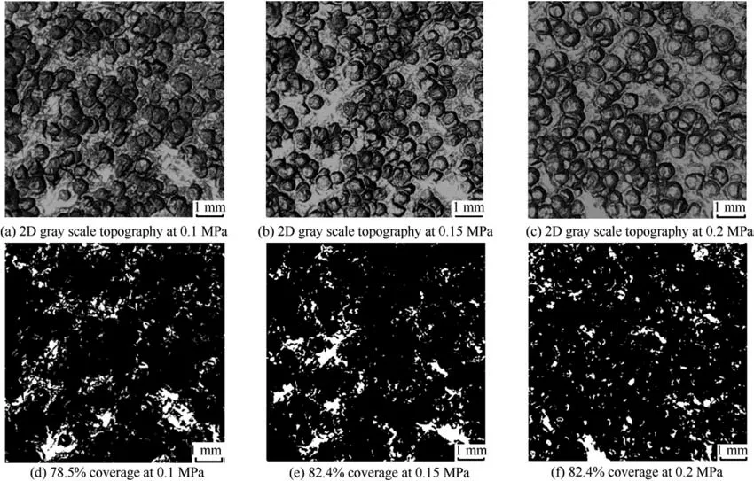
Fig. 8 2D gray scale topography and coverage calculated by ImageJ of peened surface with feeding speed of 50 mm/s at different pressures.
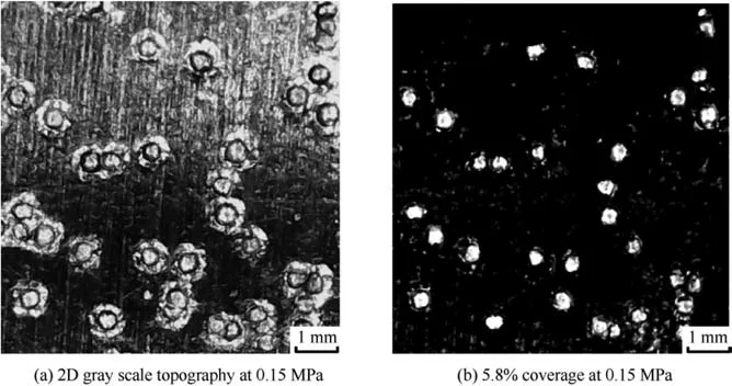
Fig. 9 2D gray scale topography of peened surface with feeding speed of 700 mm/s at pressure of 0.15 MPa.
The minimum curvature radius of the example integral panel in the 0-2, 2-3, 3-4 mm and 4-5 mm regions are 3289.47, 5712.29, 6993 mm and 8620.72 mm according to section 2.1.To 0-2 mm and 2-3 mm thickness,it can be formed at 0.1 MPa.To the 3-4 mm thickness,the pressure corresponding to the intersection point of the minimum curvature radius of the panel and the curvature radius of the specimens is 0.12 MPa. The pressure in the 4-5 mm thickness is 0.15 MPa.Therefore, air pressure is set to 0.15 MPa for forming the whole integral panel.
3.4. Prediction of feeding speed
Shot peen forming experiments are conducted based on the plate specimens and the optimal air pressure, by changing the feeding speed to forming the different thickness plate specimen. The regressive analysis method is used to analyze the relationship between each parameter and shaped curvature radius according to the results of experiments.
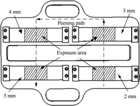
Fig. 10 Clamping and shot peening path of specimens.
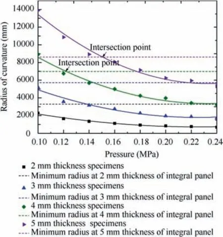
Fig. 11 Curvature radius under different air pressure of plate specimens.
Test specimens with four kinds of thickness 2,3,4 mm,and 5 mm were peened with a constant pressures 0.15 MPa and the incremental coefficient of feeding speed is set as 1.3,11 series of feeding speed was selected: 50, 65, 84.5, 109.9, 142.8, 185.6,241.3, 314.1, 408.3, 530.8, 690 mm/s, respectively. For each feeding speed, two samples were peened for repeatability.Therefore, a total of 88 specimens have been tested, as listed in Table 5.
Fig. 12 shows the formed specimens, and the forming curvature radius of specimens under different thicknesses and different feeding speed as shown in Fig. 13. It can be found that the curvature radius of the specimens increases and the deformation of the specimens decreases gradually with the increase of the feeding speed and the thickness of the specimens.Due to the increase of the feeding speed,the coverage on the surface of the specimen is reduced,and the total kinetic energy acting on the specimen is gradually reduced.At the same time,the deformation resistance of the specimens increases with the increase of thickness.
With reference to the results of experiments,the reasonable mathematical equation is assumed to take the form,

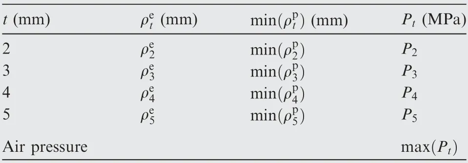
Table 4 Air pressure to form integral panel.

Table 5 Groups of experiment.
where R is shaped curvature radius.t is thickness of specimen.v is feeding speed.
Making a log transformation on both sides of Eq. (5), it is derived to the Eq. (6).

Assuming y=lnR,b=lnk,x1=lnt,x2=lnv thus,

So Eq. (5) is transformed into a linear form which can be resolved by multiple linear regression method. Least-square method is used to calculate the parameters in Eq. (8),

So the equation with values for the relation between shaped curvature radius and process parameters is,

According to Eq. (9), the index of thickness is 2.0241, and the curvature radius is proportional to the square of thickness,similar to the result of Shang.25Substituting the process values of experiments into the mathematical equation model, the regressive curvature radius is calculated and compared with the experimental curvature radius. As shown in Fig. 12, the average deviation between the regressive curvature radius from the mathematical equation model and the measured experimental curvature radius is 8.7%. So this mathematical equation model derived from experimental data is accurate and can be utilized in engineering manufacturing.
Eq. (9) is transformed to obtain the relationship between feeding speed, thickness and curvature radius. It is derived to the Eq. (10).

4. Verification and results
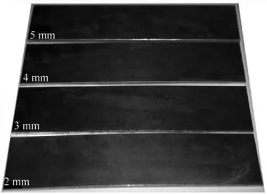
Fig. 12 Formed plate specimens.
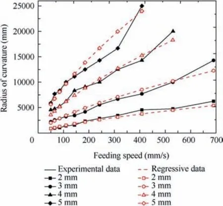
Fig. 13 Comparison of experimental and regressive data.
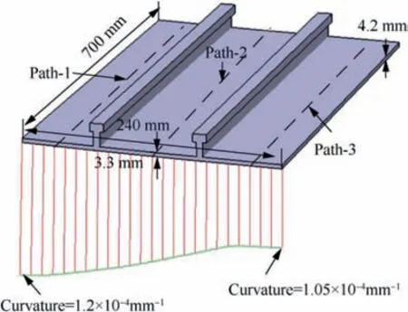
Fig. 14 Verification of integral panel part.
In order to verify the validity of the calculated method, the local area of the integral panel of Fig.1 was taken for calculation.The peening path is divided according to the extreme curvature curves of outer surface,as shown in Fig.14.Take peening path-2 as an example, scattering and extracting the thickness and curvature radius of the path, and the thickness distribution range is from 3.3 mm to 4.2 mm, the curvature radius distribution ranges is from 6000 mm to 7200 mm.According to the Eq.(10),the feeding speed of the path is calculated, and the thickness and curvature radius distribution and the calculated feeding speed are shown in Fig. 15.
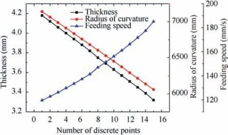
Fig. 15 Distribution of thickness, curvature radius and calculated feeding speed of peening path-2 discrete points.
The integral panel part was formed by calculated feeding speed as shown in Fig. 16(a). The deviation between the point cloud model obtained by Handyscan 500 3D laser scanner equipment and the design model is presented in Fig. 16(b),the average deviation of forming part outer shape is 0.496 mm, can meet the forming accuracy requirements. And the results proved that the feeding speed for forming the integral panel calculated by the regression equation based on experimental data of uniform thickness specimen is reasonable.
5. Conclusions
In this research,a progressive shot peening parameters predict method is presented for forming integral panel.The invariable parameters are determined according to the empirical data and machine type firstly. Then the optimal value of air pressure and feeding speed range for the whole shot peening is selected by the experimental data. Finally, the feeding speed for every shot peening path is predicted by regression equation. The analysis results reveal that this method can achieve accurate forming of the integral panel.
(1) To the stringer-structural integral panel with variable thickness and curvature, the shot peening parameters are determined based on progressive experiments. It is suitable for forming the Al7050-T7451 integral panel with base body thickness from 2 mm to 5 mm and curvature radius from 3200 mm to 16,000 mm by using MPPF20000.
(2) T-shaped stringer-structural specimens with 21 mm thickness, 12 mm top width, 6 mm bottom width and 6.5 mm between top stringer and bottom stringer are compared with the plate specimens at the feeding speeding from 65 mm/s to 241.3 mm/s and peened along the middle of the two stringers, the maximum outer shape error range is 3.9%. Thus, plate was used as the equivalent structure of T-shaped stringer-structural to acquire experimental data.
(3) The process parameters of the local area about the integral panel are calculated and validated by using the established regression equation. The overall deviation of 0.496 mm indicates that the progressive shot peening parameters prediction method enables precise forming of the integral panel.
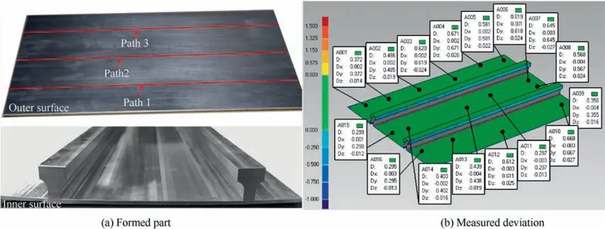
Fig. 16 Formed part and deviation between point cloud model and design model.
In the future,it is necessary to consider the large-sized and doubly-curved outer surface integral panel part. And for the different shaped and geometrical dimensions stringer and other complex structures, the forming relationship between structural specimens and plate specimens should be compared.
Declaration of Competing Interest
The authors declare that they have no known competing financial interests or personal relationships that could have appeared to influence the work reported in this paper.
Acknowledgement
This study was supported by the National Level Project of China.
 CHINESE JOURNAL OF AERONAUTICS2021年5期
- CHINESE JOURNAL OF AERONAUTICS的其它文章
- Ferrofluid moving thin films for active flow control
- Preliminary study on heat flux measurement data of TT-0 flight test
- An analysis and enhanced proposal of atmospheric boundary layer wind modelling techniques for automation of air traffic management
- Jet sweeping angle control by fluidic oscillators with master-slave designs
- Hot deformation behavior and microstructure evolution of the laser solid formed TC4 titanium alloy
- Electrochemical trepanning with an auxiliary electrode
